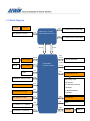
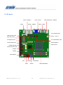
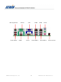
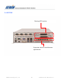
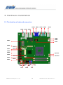
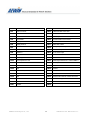
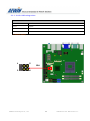
1
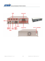
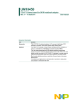
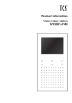
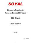
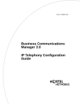
User Manual GMB-8300 Embedded Gaming System Support 3rd Generation Intel® Core™ Mobile Processor And QM77, 3 Display, Audio, PCIe X16, 2 GbE, 5 COM, 4 USB3.0, 64 x I/O, NVRAM, Flash ROM, 2nd RTC, Intrusion Detection, Optional Authenticate Chip Ver. Release Date Update 1.0 2013.9.20 Release 1.1 2014.02.25 system information updated Importance : Please do backup system OS image before using AEWIN Technologies Co., Ltd 1 GMB-8300 User Manual Rev.1.1 Copyright The content of this document and software with this product are copyrighted by AEWIN technologies Co., Ltd, This document contains proprietary information protected by copyright. All rights are reserved; no part of this manual may be reproduced, copied, translated or transmitted in any form or by any means without prior written permission of the manufacturer. The content of this document is intended to be accurate and reliable; the original manufacturer assumes no responsibility for any inaccuracies that may be contained in this manual. The original manufacturer reserves the right to make improvements to the products described in this manual at any time without prior notice Trademark All other product names mentioned herein are used for identification purpose only and may be trademarks and/or registered trademarks of their respective companies Limitation of liability While reasonable efforts have been made to ensure the accuracy of this document, the manufacturer and distributor assume no liability resulting from errors or omissions in this document, or from the use of the information contained herein. For more information or other AEWIN products, please visit our website http://www.aewin.com.tw. For technical supports, please send your inquiry to [email protected] AEWIN Technologies Co., Ltd 2 GMB-8300 User Manual Rev.1.1 Packing list Before use this product, please make sure that the following materials have been shipped. 1 x GMB-8300 System 1 x SATA cable, L/ 200mm ( p/n: 46L-SATA11-00 ) 1 x 12V/5V SATA power cable , L/ 150mm ( p/n: 46L-IPOW41-00 ) 1 x CD utility p/n: 46L-SATA11-00 p/n: 46L-IPOW41-00 p/n: TBD Model Name Description GMB-8300C Mini-ITX with Intel® QM77 chipset, 2 GLAN, DDR3 up to 8GB, HDMI, DVI, VGA, LVDS, SATA, COM, PCIe X16 slot * If any of those items are missing or damaged, please contact with sales representative or distributor AEWIN Technologies Co., Ltd 3 GMB-8300 User Manual Rev.1.1 Optional Accessory Photo Model Name P/N: GP002-221 Mini-DP-to-DVI-D Active adapter P/N: 46L-ICOM38-00 Dual D-Sub 9-pin COM port card, L/ 250mm, with bracket P/N: 46L-IUSB07-AA Dual USB cable, L/ 250mm, with bracket P/N: 46L-IPOW102-00 P4 4-pin to DC Jack lockable power cable, L/ 200mm P/N : GP002-226, Radeon 6760, x6 DP P/N: P/N : GP002-222, Radeon 6760, x4 DP P/N : GP002-223, Radeon 6460, x4 DP AMD Radeon Graphic card P/N R135A Gaming I/O testing board P/N 46L-ICOM26-00 R135A I/O cable of GA-P100 AEWIN Technologies Co., Ltd 4 GMB-8300 User Manual Rev.1.1 Safety Information To prevent electrical shock hazard, disconnect the power cable from the electrical outlet before relocating the system. When adding or removing devices to or from the system, ensure that the power cables for the devices are unplugged before the signal cables are connected. If possible, disconnect all power cables from the existing system before you add a device. Before connecting or removing signal cables from the motherboard, ensure that all power cables are unplugged. Seek professional assistance before using an adapter or extension cord. These devices could interrupt the grounding circuit. Make sure that your power supply is set to the correct voltage in your area. If you are not sure about the voltage of the electrical outlet you are using, contact your local power company. If the power supply is broken, do not try to fix it by yourself. Contact a qualified service technician or your retailer. Operation Safety Before installing the motherboard and adding devices on it, carefully read all the manuals that came with the package. Before using the product, make sure all cables are correctly connected and the power cables are not damaged. If you detect any damage, contact your dealer immediately. To avoid short circuits, keep paper clips, screws, and staples away from connectors, slots, sockets and circuitry. Avoid dust, humidity, and temperature extremes. Do not place the product in any area where it may become wet. Place the product on a stable surface. If you encounter technical problems with the product, contact a qualified service technician or your retailer. AEWIN Technologies Co., Ltd 5 GMB-8300 User Manual Rev.1.1 Content 1. General Information ............................................................................................................................. 7 1.1 Introduction ......................................................................................................................................... 7 1.2 Specification of board and Gaming I/O ............................................................................................... 8 1.3 Block Diagram .....................................................................................................................................11 1.4 Board and System Layout Dimension ................................................................................................ 12 1.5 IO ports .............................................................................................................................................. 15 1.6 SYSTEM............................................................................................................................................... 17 2. Hardware installation ......................................................................................................................... 19 2.1 The location of onboard connectors .................................................................................................. 19 2.2 The location of onboard jumpers ...................................................................................................... 21 2.3 The function list of onboard jumpers setting .................................................................................... 22 2.4 The pin define of onboard pin header ............................................................................................... 26 2.5 Gaming I/O Pin Definition .................................................................................................................. 50 AEWIN Technologies Co., Ltd 6 GMB-8300 User Manual Rev.1.1 1. General Information 1.1 Introduction MB-8300, a Mini-ITX board supporting Intel® Ivy Bridge / Sandy Bridge Mobile CPU with integrated Intel® QM77 Express chipset. Onboard display includes HDMI, DVI-D, VGA and 24-bit dual channel LVDS and two DDR3 SO-DIMM supports a maximum of 16GB DDR3 1600 of system memory. MB-8300 delivers flexible expansion slots allowing customers to install one PCI-Express X16 card and two Mini-PCIe cards. It is built with a SIM card holder capable of installing a SIM card with a Full-size Mini-PCIe 3G module for wireless connection. For half-size Mini-PCIe socket it also supports mSATA SSD as storage device (Optional). Furthermore it comes with a PCI-Express X1 slot that can be paired with AEWIN’s riser card for an additional 1 ~ 3 PCI slots for various application. MB-8300 is designed with a video/audio encode chip that supports 4-channel inputs under D1 resolution at real-time. AEWIN will provide software development kit allowing easy application development. On the I/O front the MB-8300 provides plenty of connectivity. 2 x Intel® i211AT GbE LAN controller, 1 x RS232/422/485 & 3 x RS232, 4 x USB3.0 + 6 x USB2.0, HD Audio, PS/2 Keyboard/Mouse, 4 x SATA with RAID O/1/5/10 and a LPC pin-header supporting AEWIN’s TPM module for the added information protection. The MB-8300 accepts a wide range 8V ~ 32V DC input suitable for a variety of applications in digital signage, POS, kiosks, and factory automation. About AEWIN AEWIN offers reliable and solid products which are produced under Management System Standards: ISO9001-2000 Certificate. The certificate keeps us focused on our quality objectives of management and environmental production. Its willingness to customize standard products for meet unique customer needs makes AEWIN different. All ODM projects are welcome. Years of experiences enables AEWIN to fulfill the customer’s vision, by delivering products to exact specifications. AEWIN R&D team is proud of its strong engineering background. R&D professionals account for 25% of the AEWIN workforce. We focus on developing new products for both emerging and established markets For more information about OEM/ODM, please contact us Email: [email protected] AEWIN Technologies Co., Ltd : TEL: +886-2-8692-6677 7 GMB-8300 User Manual Rev.1.1 1.2 Specification of board and Gaming I/O System Specification System From Factor Mini-ITX motherboard CPU Intel® Core™ i7/i5/i3 Processor Mobile processor, Ivy Bridge, socket 988B. Intel® Core™ i7-3610QE, 2.3 GHz, Qual-Core/45W Intel® Core™ i5-3610ME, 2.7 GHz, Dual-Core/35W Intel® Core™ i5-2510E , 2.5 GHz, Dual-Core/35W Intel® Core™ i3-3120ME , 2.4 GHz, Dual-Core/35W Intel® Celeron® B810 , 1.6 GHz, Dual-Core/35W Chipset Intel QM77 Express chipset Memory 2 x 204-pin DDR3 1333/1600 MHz / SODIMM up to 16GB, w/o ECC support BIOS AMI SPI BIOS SSD Half-size Mini-PCIe socket support mSATA SSD Watchdog timer 255 levels, 1 ~ 255 sec Expansion 1 x PCI-Express X16 slot 1 x PCI-Express X1 ( work with riser card for PCIe X1 or PCI 32-bit/33 MHz expansion ) 1 x Full-size Mini-PCIe socket w/ USB, PCIe signal 1 x Half-size Mini-PCIe socket w/ USB, PCIe or SATA signal ( Default is SATA signal ) Note: Need to inform us to modify hardware before ship if want to Half-size Mini-PCIe support PCIe signal Board Size 170mm x 170mm System Dimension 320mm x 200mm x 83.2mm Operating Temp. 0°C~60°C (32°F~140°F) Storage Temp. .-20°C~80°C (-4°F~176°F) Operating Hum. 10%~90% (non-condensing) Display Chipset Intel® processor integrated Display interface 1 x external HDMI 1.4a 1 x external VGA 1 x external DVI-D 1 x internal 24-bit Dual Channel LVDS AEWIN Technologies Co., Ltd 8 GMB-8300 User Manual Rev.1.1 I/O Series Port Internal : 1 x RS232/422/485 ( COM2 ), 2 x RS232 External : 1 x RS232 SATA 2 x SATA 3Gb/s + 2 x SATA 6Gb/s, w/ RAID 0/1/5/10 USB External : 4 x USB3.0 + 2 x USB2.0 Internal : 4 x USB2.0 Ethernet 1 x Intel® 82583V PCIe controller 1 x Intel® 82579LM PHY support WOL & Intel® AMT 8.0 support Audio Line-in/out , Mic-in Digital I/O 8-bit GPIO interface ( pitch : 2.0 ) LPC 1 x LPC 2 x 10-pin header for Optional TPM module Others 2 x cooling Fan header ( Smart fan support ) , 1 x PS/2 keyboard/Mouse 1 x Front Panel header for power on/off, reset, HDD/power LED indicator 1 x LVDS Backlight/inverter pin-header ( w/ house 2 x 12V/5V DC out for HDD ) , 1 x SMbus ( 5-pin wafer ) Power Power in Wide range DC 8V ~ 32V input ( AT/ATX mode select by jumper ) Connector 1 x internal P4 4-pin power connector Note : All specifications and photos are subject to change without notice AEWIN Technologies Co., Ltd 9 GMB-8300 User Manual Rev.1.1 Gaming I/O Specifications Gaming ROM 2MB Flash ROM NVRAM On-board 1MB battery backed SRAM (Optional 2MB) Timers Programmable timer with timeout interrupt Watchdog Timer 255 levels timer interval, (1sec. to 255min.), setup by software. Intrusion Detection Operates with and without system power 6x Intrusion detection inputs Logs date/time of last 30 events Events include door status, system resets/brownouts On-chip EEPROM backup Digital I/O - 32x photo-couple isolated input - 32x 500mA current sink output O/S Windows XP(e) Linux Security Security FPGA Authenticate Chip (Optional) Boot ROM Mechanical and Environment Environmental Operating Temperature: 0 – 60 ºC (32 ºF – 140 ºF) Storage Temperature: -20 – 85 ºC (-4 ºF – 185 ºF) Relative Humidity: 10-85 % RH, non-condensing Compliant FCC/CE Class A Dimension 163mm (L) x 107mm (H) Applications Main Application Video slot machines (Class II/III) Video lottery terminals Amusement game machines Master unit of roulette machine Downloadable gaming terminal High end vending machines ATMS/Cash machines; AEWIN Technologies Co., Ltd 10 GMB-8300 User Manual Rev.1.1 1.3 Block Diagram Optional Chipset DDR 1 x DDR3 204-pin SO-DIMM Intel® Core™ i7/i5/i3 PCIe Socket 988B Processor PCI-Express X16 slot DDR 1 x DDR3 204-pin SO-DIMM X4 DMI X4 FDI PCIe DDI B HDMI & USB Level Shifter Full-size Mini-PCIe Intel® QM77 SATA or PCIe Express Chipset & USB DDI C DVI-D Level Shifter Half-size Mini-PCIe VGA VGA LPC F81866A Super I/O LVDS 24-bit Dual-channel LVDS Watch Dog Timer H/W Monitor PCIe Intel® 82579LM GLAN PS2 Keyboard / Mouse 8-bit GPIO 1 x RS232/422/485 PCIe Intel® 82583V GLAN 3 x RS232 PCIe HDA PCI-Express X1 slot ALC886-GR SPI BIOS USB 4 x USB3.0 + 4 x USB2.0 PCIe CX25854 SATA 2 x SATA3 + 2 x SATA2 AEWIN Technologies Co., Ltd 11 Video In GMB-8300 User Manual Rev.1.1 1.4 Board and System Layout Dimension AEWIN Technologies Co., Ltd 12 GMB-8300 User Manual Rev.1.1 AEWIN Technologies Co., Ltd 13 GMB-8300 User Manual Rev.1.1 AEWIN Technologies Co., Ltd 14 GMB-8300 User Manual Rev.1.1 1.5 IO ports GLAN + USB3.0 Audio VGA + DVI-D GLAN + USB3.0 PS2 Key/Mouse + USB2.0 COM + HDMI Intel® QM77 4-ch Video decoder Half-size Mini-PCIe DC 8V ~ 32V In SIM card holder PCI-Express X16 4-ch Video/Audio Input Full-size Mini-PCIe Socket 988B for Intel® i7/i5/i3 RS232/422/485 24-bit Dual-CH LVDS RS232 RS232 Dual USB2.0 LPC SATA2 GPIO AEWIN Technologies Co., Ltd Intel® QM77 SATA3 15 DDR3 SO-DIMM GMB-8300 User Manual Rev.1.1 PS2 Key/Mouse Dual USB2.0 RS232 HDMI AEWIN Technologies Co., Ltd VGA GLAN DVI-D Dual USB3.0 16 GLAN Audio Dual USB3.0 PCIe X16 slot GMB-8300 User Manual Rev.1.1 1.6 SYSTEM Gaming I/O Function Expansion slot for miscellanouse applications AEWIN Technologies Co., Ltd 17 GMB-8300 User Manual Rev.1.1 AEWIN Technologies Co., Ltd 18 GMB-8300 User Manual Rev.1.1 2. Hardware installation 2.1 The location of onboard connectors CN38 CN34 CN32 CN35 CN36 CN37 CN42 CN31 CN30 CN28 CN27 CN29 CN26 CN21 CN25 CN23 CN39 CN19 Sys Fan CN16 CN14 CN12 CN40 CPU Fan CN11 CN6 CN5 CN8 AEWIN Technologies Co., Ltd CN7 CN1 CN10 CN9 CN4 CN3 CN2 19 GMB-8300 User Manual Rev.1.1 Label Function Label Function CN1 Low Pin Count CN22 Half-size Mini-PCIe LED CN2 SATA3-1 CN23 Full-size Mini-PCIe LED CN3 SATA2-1 CN24 PCI-Express X16 slot CN4 8-bit GPIO CN25 Full-size Mini-PCIe socket CN5 SATA power-1 CN26 Half-size Mini-PCIe socket CN6 SATA power-2 CN27 SIM card holder CN7 USB 6/7 CN28 P4 4-pin power input connector CN8 USB 8/9 CN29 4-ch Audio input CN9 SATA3-2 CN30 4-ch Video input CN10 SATA2-2 CN31 RJ45 LAN + Dual USB 3.0 CN11 SPI Programmer CN32 RJ45 LAN + Dual USB 3.0 CN12 PCI-Express X1 slot CN33 PS2 keyboard/mouse + Dual USB 2.0 CN13 N/C CN34 Audio jack CN14 COM4 CN35 VGA connector CN15 N/C CN36 COM1 CN16 Power on/off, Reset, HDD/Power LED CN37 HDMI connector CN17 N/C CN38 DVI-D connector CN18 N/C CN39 24-bit Dual Channel LVDS connector CN19 COM3 CN40 LVDS Backlight inverter CN20 N/C CN41 N/C CN21 COM2 CN42 N/C AEWIN Technologies Co., Ltd 20 GMB-8300 User Manual Rev.1.1 2.2 The location of onboard jumpers JP3 JP4 JP5 JP1 Label Function JP1 CMOS Clear jumper JP2 N/C JP3 AT/ATX power mode jumper select JP4 Panel Voltage ( VCC ) select JP5 LVDS backlight control mode select AEWIN Technologies Co., Ltd 21 GMB-8300 User Manual Rev.1.1 2.3 The function list of onboard jumpers setting - 2.3.1 : JP1 for for Clear CMOS If you want to clean the CMOS data, set jumper to 2-3 just for few seconds, Then, Move the jumper back to 1-2 pin JP1 Closed Pin Result 1-2 * Normal 2-3 Clear CMOS * Default setting 1 JP1 3 AEWIN Technologies Co., Ltd 22 GMB-8300 User Manual Rev.1.1 - 2.3.2: JP3 for ATX / AT mode JP3 Closed Pin Result 1-2 * ATX mode 2-3 AT mode * Default setting 1 JP3 3 AEWIN Technologies Co., Ltd 23 GMB-8300 User Manual Rev.1.1 - 2.3.3 : JP4 for LVDS voltage select JP4 Closed Pin Result 1-2 * +3.3V 3-4 +5V 5-6 +12V * Default setting 1 5 JP4 2 AEWIN Technologies Co., Ltd 6 24 GMB-8300 User Manual Rev.1.1 - 2.3.4 : JP5 for LVDS brightness control mode JP5 Closed Pin Result 1-2 PWM mode 2-3 * DC Level * Default setting 3 AEWIN Technologies Co., Ltd 1 JP5 25 GMB-8300 User Manual Rev.1.1 2.4 The pin define of onboard pin header - 2.4.1 : CN1 for Low Pin Count pin-header CN1 : 2 x 7 header , pitch 2.0 mm Pin Signal Pin Signal 1 +3.3V 2 LAD0 3 LAD1 4 LAD2 5 LAD3 6 LFRAME 7 Reset 8 +5V 9 PORT80_PCLK 10 LPME 11 GND 13 SERIRQ Key 14 LDRQ 2 3 1 13 1 CN1 14 AEWIN Technologies Co., Ltd 2 26 GMB-8300 User Manual Rev.1.1 2.4.2 : CN4 for 8-bit GPIO CN4 : 2 x 6 header , pitch 2.0 mm Pin Signal Pin Signal 1 +3.3V 2 GPI0 3 GPI1 4 GPI2 5 GPI3 6 GPO0 7 GPO1 8 GPO2 9 GPO3 10 Key 11 +5V 12 GND 12 2 3 1 11 CN4 2 AEWIN Technologies Co., Ltd 1 27 GMB-8300 User Manual Rev.1.1 - 2.4.3 : CN5 & CN6 for 4-pin HDD power CN5 : 4-pin wafer for SATA power connector Pin Signal Pin Signal 1 +12V 2 GND 3 GND 4 +5V Note: Maximum output current 12V/1A, 5V/1A CN6 : 4-pin wafer for SATA power connector Pin Signal Pin Signal 1 +12V 2 GND 3 GND 4 +5V Note: Maximum output current 12V/1A, 5V/1A 4 CN5 1 4 1 CN6 AEWIN Technologies Co., Ltd 28 GMB-8300 User Manual Rev.1.1 - 2.4.4 : CN7 & CN8 for USB 6/7 , USB 8/9 CN7: 2 x 5 header , pitch 2.54 mm Pin Signal Pin Signal 1 +5V 2 +5V 3 USB6_ data- 4 USB7_data- 5 USB6_ data+ 6 USB7_data+ 7 GND 8 GND 9 Key 10 GND CN8: 2 x 5 header , pitch 2.54 mm Pin Signal Pin Signal 1 +5V 2 +5V 3 USB8_ data- 4 USB9_data- 5 USB8_ data+ 6 USB9_data+ 7 GND 8 GND 9 Key 10 GND 10 9 CN7 2 1 10 9 CN8 2 1 AEWIN Technologies Co., Ltd 29 GMB-8300 User Manual Rev.1.1 2.4.5 : CN9 for SATA 3.0 connector CN9 : SATA 2.0 connector Pin Signal Pin Signal 1 GND 2 TX+ 3 TX- 4 GND 5 RX- 6 RX+ 7 GND CN10 for SATA 2.0 connector CN10 : SATA 2.0 connector Pin Signal Pin Signal 1 GND 2 TX+ 3 TX- 4 GND 5 RX- 6 RX+ 7 GND 7 CN9 1 7 CN10 1 AEWIN Technologies Co., Ltd 30 GMB-8300 User Manual Rev.1.1 - 2.4.6 : CN11 for SPI programmer CN11 : 2 x 4 header , pitch 2.54 mm Pin Signal Pin Signal 1 +3.3V 2 GND 3 CS_N ( Chip Select ) 4 SCLK ( Serial Clock) 5 MISO ( Master Input, Slave Output ) 6 MOSI ( Master Output, Slave Input ) 7 N/C 8 FLASH_IO 7 1 CN11 8 2 AEWIN Technologies Co., Ltd 31 GMB-8300 User Manual Rev.1.1 - 2.4.7 : CN12 for PCI-Express X1 slot Note: This slot could work with AEWIN’s RE-S01 r-ser card to get PCIe X16 & PCI expansion slots Regarding the PCIe X16 slot, The Max. power that could support is 35W PCIe add-on card Pin Side B Side A 1 +12V PRSNT1 2 +12V +12V 3 +12V +12V 4 GND GND 5 SMCLK TCK 6 SMDAT TDI 7 GND TOD 8 +3.3V TMS 9 RST +3.3V 10 +3.3V AUX +3.3V 11 WAKE PWRGD Key Notch 12 Reserved GND 13 GND REFCLK+ 14 HSOp REFCLK- 15 HSOn GND 16 GND HSIp 17 PRSNT2 HSIn 18 GND GND AEWIN Technologies Co., Ltd Configuration of MB-8300C with RE-S01 riser card 32 GMB-8300 User Manual Rev.1.1 - 2.4.8 : CN14 for COM4 , RS232 CN14 : 2 x 5 header, pitch 2.00 mm Pin Signal Pin Signal 1 DCD, Data carrier detect 2 DSR, Data set ready 3 RXD, Receive Data 4 RTS, Request to send 5 TXD, Send Data 6 CTS, Clear to se 7 DTR, Data Terminal Ready 8 RI, Ring indicator 9 GND 10 N/C 1 2 CN14 9 10 AEWIN Technologies Co., Ltd 33 GMB-8300 User Manual Rev.1.1 - 2.4.9 : CN16 for front Panel pin header CN16 : 2 x 4 header , pitch 2.54 mm Pin Signal Pin Signal 1 HDD_LED+ 2 Power_LED+ 3 HDD_LED- 4 GND 5 GND 6 GND 7 RESET+ 8 Power_Switch 7 1 CN16 8 AEWIN Technologies Co., Ltd 2 34 GMB-8300 User Manual Rev.1.1 - 2.4.10 : CN19 for COM3 , RS232 CN19 : 2 x 5 header, pitch 2.00 mm Pin Signal Pin Signal 1 DCD, Data carrier detect 2 DSR, Data set ready 3 RXD, Receive Data 4 RTS, Request to send 5 TXD, Send Data 6 CTS, Clear to se 7 DTR, Data Terminal Ready 8 RI, Ring indicator 9 GND 10 N/C 1 2 9 10 AEWIN Technologies Co., Ltd CN19 35 GMB-8300 User Manual Rev.1.1 - 2.4.11 : CN21 for COM2 , RS232/422/485 Note: COM2 RS-232/422/485 can be set by BIOS setting. Default is RS-232. CN21 : 2 x 5 header , Pitch 2.00 mm Pin RS232 mode RS422 mode RS485 mode 1 DCD, Data carrier detect TXD- TXD- 2 DSR, Data set ready 3 RXD, Received Data TXD+ TXD+ 4 RTS, Request to send 5 TXD, Transmitted Data 6 CTS, Clear to sent 7 DTR, Data terminal ready 8 RI, Ring indicator 9 GND 10 N/C 1 2 9 10 AEWIN Technologies Co., Ltd RXD+ RXD- CN21 36 GMB-8300 User Manual Rev.1.1 BIOS setting manual : AEWIN Technologies Co., Ltd 37 GMB-8300 User Manual Rev.1.1 - 2.4.12 : CN22 for Half-size Mini-PCIe WLAN LED indictor CN22 : 1 x 2 , 2-pin wafer Pin Signal Pin Signal 1 LED_WLAN 2 +3.3V Note: Half-size Mini-PCIe card could support SATA or PCIe signal. The default setting is SATA signal. Hardware modification required if want to change signal from SATA to PCIe. 1 AEWIN Technologies Co., Ltd 2 CN22 38 GMB-8300 User Manual Rev.1.1 - 2.4.13 : CN23 for Full-size Mini-PCIe WLAN LED indictor CN23 : 1 x 2 , 2-pin wafer Pin Signal Pin Signal 1 LED_WLAN 2 +3.3V 1 2 CN23 AEWIN Technologies Co., Ltd 39 GMB-8300 User Manual Rev.1.1 - 2.4.14 : CN25 for Full-size Mini-PCIe socket Pin Signal Pin Signal 1 WAKE 27 GND 2 +3.3V AUX 28 +1.5V 3 N/C 29 GND 4 GND 30 SMBCLK 5 N/C 31 PETN0 6 +1.5V 32 SMBDATA 7 CLKREQ 33 PETP0 8 UIM_PWR 34 GND 9 GND 35 GND 10 UIM_DATA 36 USB_D- 11 REFCLK- 37 GND 12 UIM_CLK 38 USB_D+ 13 REFCLK+ 39 +3.3V AUX 14 UIM_RESET 40 GND 15 GND 41 +3.3V AUX 16 UIM_VPP 42 LED_WWAN 17 UIM_C8 43 GND 18 GND 44 LED_WLAN 19 UIM_C4 45 N/C 20 W_Disable 46 N/C 21 GND 47 N/C 22 PERST 48 +1.5V 23 PERN0 49 N/C 24 +3.3V AUX 50 GND 25 PERP0 51 N/C 26 GND 52 +3.3V AUX AEWIN Technologies Co., Ltd CN25 40 GMB-8300 User Manual Rev.1.1 - 2.4.15 : CN26 for Half-size Mini-PCIe socket. Note: Half-size Mini-PCIe card could support SATA or PCIe signal. The default setting is SATA signal. Hardware modifications required if want to change signal from SATA to PCIe. Pin Signal Pin Signal 1 WAKE 27 GND 2 +3.3V AUX 28 +1.5V 3 Reserved 29 GND 4 GND 30 SMBCLK 5 Reserved 31 PETN0 6 +1.5V 32 SMBDATA 7 CLKREQ 33 PETP0 8 Reserved 34 GND 9 GND 35 GND 10 UIM_DATA 36 USB_D- 11 REFCLK- 37 Reserved 12 Reserved 38 USB_D+ 13 REFCLK+ 39 Reserved 14 Reserved 40 GND 15 GND 41 Reserved 16 Reserved 42 LED_WWAN 17 Reserved 43 Reserved 18 GND 44 LED_WLAN 19 Reserved 45 Reserved 20 Reserved 46 N/C 21 GND 47 Reserved 22 PERST 48 +1.5V 23 PERN0 49 Reserved 24 +3.3V AUX 50 GND 25 PERP0 51 Reserved 26 GND 52 +3.3V AEWIN Technologies Co., Ltd CN26 41 GMB-8300 User Manual Rev.1.1 - 2.4.16 : CN27 for SIM holder CN27 : SIM card holder Pin Signal Pin Signal C1 VCC C2 RESET C3 CLOCK C4 Reserved C5 GND C6 VPP C7 I/O C8 Reserved C1 C4 CN27 C5 C8 AEWIN Technologies Co., Ltd 42 GMB-8300 User Manual Rev.1.1 - 2.4.17 : CN28 for internal 4-pin power input CN19 : ATX 2 x 2 Pin Signal Pin Signal 1 GND 2 GND 3 8V ~ 32V DC input 4 8V ~ 32V DC input 3 1 4 2 CN28 AEWIN Technologies Co., Ltd 43 GMB-8300 User Manual Rev.1.1 - 2.4.18 : CN29 for 4-ch Audio input Note: This function for MB-8300B model only CN29 : 2 x 5 header, pitch 2.00 mm Pin Signal Pin Signal 1 GND 2 Audio_IN_1 3 GND 4 Audio_IN_2 5 GND 6 Audio_IN_3 7 GND 8 Audio_IN_4 9 GND 10 N/C 2 10 1 9 CN29 AEWIN Technologies Co., Ltd 44 GMB-8300 User Manual Rev.1.1 - 2.4.19 : CN30 for 4-ch Video input Note: This function for MB-8300B model only CN29 : 2 x 5 header, pitch 2.00 mm Pin Signal Pin Signal 1 GND 2 Video_IN_1 3 GND 4 Video_IN_2 5 GND 6 Video_IN_3 7 GND 8 Video_IN_4 9 GND 10 N/C 2 10 1 9 CN30 AEWIN Technologies Co., Ltd 45 GMB-8300 User Manual Rev.1.1 - 2.4.20 : CN39 for 24-bit Dual Channel LVDS CN39 : connector type : DF13A-40DP-1.25V Pin Signal Pin Signal Pin Signal 1 LVDS_VCC 15 LVDSA_1+ 29 GND 2 LVDS_VCC 16 LVDSB_1+ 30 GND 3 LVDS_VCC 17 GND 31 DDC_Clock 4 LVDS_VCC 18 GND 32 DDC_Data 5 GND 19 LVDSA_2- 33 GND 6 GND 20 LVDSB_2- 34 GND 7 LVDSA_0- 21 LVDSA_2+ 35 LVDSA_3- 8 LVDSB_0- 22 LVDSB_2+ 36 LVDSB_3- 9 LVDSA_0+ 23 GND 37 LVDSA_3+ 10 LVDSB_0+ 24 GND 38 LVDSB_3+ 11 GND 25 LVDSA_Clock- 39 SMB_Clock 12 GND 26 LVDSB_Clock- 40 SMB_Data 13 LVDSA_1- 27 LVDSA_Clock+ 14 LVDSB_1- 28 LVDSB_Clock+ 2 1 CN39 40 39 AEWIN Technologies Co., Ltd 46 GMB-8300 User Manual Rev.1.1 BIOS setting for LVDS Resolution: AEWIN Technologies Co., Ltd 47 GMB-8300 User Manual Rev.1.1 - 2.4.21 : CN40 for LVDS backlight CN3: 1 x 5 wafer , Pitch : Pitch 2.0 mm Pin Signal Pin Signal 1 +12V 2 GND 3 Backlight Enable 4 Backlight Control 5 +5V 5 1 AEWIN Technologies Co., Ltd CN40 48 GMB-8300 User Manual Rev.1.1 - 2.4.22 : SYS FAN for system Fan connector CN4 : 1 x 3 wafer - Pin Signal Pin Signal 1 GND 2 +12V 3 Sense 2.4.5 : CPU FAN for CPU Fan connector CN5: 1 x 3 wafer Pin Signal Pin Signal 1 GND 2 +12V 3 Sense 3 1 SYS FAN CN4 3 CPU FAN 1 AEWIN Technologies Co., Ltd 49 GMB-8300 User Manual Rev.1.1 2.5 Gaming I/O Pin Definition Board Connector Connector List Connector Description Connector Description CN1 Test Pin Headers CN2 FPGA Download Pin Headers CN3 2*25 Pin Headers (I/O) CN4 62 Pin D-SUB Connector (I/O) CN5 Microchip Download Pin Header CN6 Test Pin Headers JP1 DOOR6 Pin Headers JP2 Test Pin Headers PCI1 PCI Interface AEWIN Technologies Co., Ltd 50 GMB-8300 User Manual Rev.1.1 Connector/Jumper Setting CN2: FPGA Download Pin Headers 1 3 5 7 9 2 6 8 10 Pin Define Pin Define 1 FTCK 2 GND 3 FTDO 4 NC 5 FTMS 6 VJTAG 7 VPUMP 8 FTRST 9 FTDI 10 GND CN3: 2*25 Pin Headers (I/O) 1 3 5 7 9 11 13 15 17 19 21 23 25 27 29 31 33 35 37 39 41 43 45 47 49 2 4 6 8 10 12 14 16 18 20 22 24 26 28 30 32 34 36 38 40 42 44 46 48 50 Pin Define Pin Define 1 In16 2 Out24 3 In17 4 Out25 5 In18 6 Out26 AEWIN Technologies Co., Ltd 51 GMB-8300 User Manual Rev.1.1 7 In19 8 Out27 9 In20 10 Out28 11 In21 12 Out29 13 In22 14 Out30 15 In23 16 Out31 17 In24 18 GND 19 In25 20 GND 21 In26 22 DOOR0 23 In27 24 DOOR1 25 In28 26 DOOR2 27 In29 28 DOOR3 29 In30 30 DOOR4 31 In31 32 DOOR5 33 GND 34 GND 35 GND 36 GND 37 GND 38 GND 39 GND 40 GND 41 IO_+5V 42 IO_+12V 43 IO_+5V 44 IO_+12V 45 IO_+5V 46 IO_+12V 47 IO_+5V 48 IO_+12V 49 IO_+5V 50 IO_+12V CN4: 62 Pin D-SUB Connector (I/O) AEWIN Technologies Co., Ltd 52 GMB-8300 User Manual Rev.1.1 Pin Define Pin Define 1 In0 2 Out0 3 In1 4 Out1 5 In2 6 Out2 7 In3 8 Out3 9 In4 10 Out4 11 In5 12 Out5 13 In6 14 Out6 15 In7 16 Out7 17 In8 18 Out8 19 In9 20 Out9 21 In10 22 Out10 23 In11 24 Out11 25 In12 26 Out12 27 In13 28 Out13 29 In14 30 Out14 31 In15 32 Out15 33 GND 34 Out16 35 GND 36 Out17 37 GND 38 Out18 AEWIN Technologies Co., Ltd 53 GMB-8300 User Manual Rev.1.1 39 GND 40 Out19 41 GND 42 Out20 43 GND 44 Out21 45 GND 46 Out22 47 GND 48 Out23 49 GND 50 GND 51 GND 52 GND 53 IO_+5V 54 IO_+12V 55 IO_+5V 56 IO_+12V 57 IO_+5V 58 IO_+12V 59 IO_+5V 60 IO_+12V 61 IO_+5V 62 IO_+12V CN5: MICROCHIP Download Pin Headers 1 2 3 4 5 Pin Define Pin Define 1 MCLR 2 +3.3V 3 GND 4 ICSPDAT 5 ICSPCLK JP1: DOOR6 Pin Headers Pin Setting OPEN (Default) CLOSE Event AEWIN Technologies Co., Ltd 54 GMB-8300 User Manual Rev.1.1