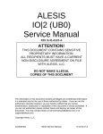
1
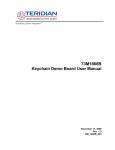
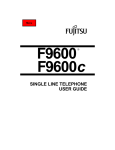
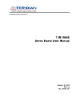
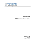
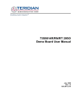
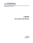
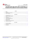
Simplifying System IntegrationTM
73M1966B
Evaluation Kit User Manual
March 19, 2009
Rev. 1.0
UM_1966B_024
73M1966B Evaluation Kit User Manual
UM_1966B_024
© 2009 Teridian Semiconductor Corporation. All rights reserved.
Teridian Semiconductor Corporation is a registered trademark of Teridian Semiconductor Corporation.
Windows is a registered trademark of Microsoft Corporation.
All other trademarks are the property of their respective owners.
Teridian Semiconductor Corporation makes no warranty for the use of its products, other than expressly
contained in the Company’s warranty detailed in the Teridian Semiconductor Corporation standard Terms
and Conditions. The company assumes no responsibility for any errors which may appear in this
document, reserves the right to change devices or specifications detailed herein at any time without
notice and does not make any commitment to update the information contained herein. Accordingly, the
reader is cautioned to verify that this document is current by comparing it to the latest version on
http://www.teridian.com or by checking with your sales representative.
Teridian Semiconductor Corp., 6440 Oak Canyon, Suite 100, Irvine, CA 92618
TEL (714) 508-8800, FAX (714) 508-8877, http://www.teridian.com
2
Rev. 1.0
UM_1966B_024
73M1966B Evaluation Kit User Manual
Table of Contents
1
Introduction ......................................................................................................................................... 5
1.1 System Requirements .................................................................................................................. 6
1.2 Package Contents......................................................................................................................... 6
1.3 Safety and ESD Notes .................................................................................................................. 6
2
Getting Started .................................................................................................................................... 7
2.1 Connecting to the PCM Test Set .................................................................................................. 8
2.2 Connecting the SPI to the PC ....................................................................................................... 8
2.3 Connecting to a Central Office Line Simulator ............................................................................. 8
Considerations When Connecting to the Telephone Network ................................................ 9
2.3.1
2.4 Graphical User Interface ............................................................................................................... 9
2.5 Connecting the Power Supply .................................................................................................... 10
2.6 Applying Power ........................................................................................................................... 10
3
Connectors and Jumpers................................................................................................................. 11
4
Using the Demo Boards ................................................................................................................... 12
5
Motherboard Schematic, PCB Layouts and BOM.......................................................................... 13
5.1 Schematic ................................................................................................................................... 13
5.2 PCB Layouts ............................................................................................................................... 14
5.3 Bill of Materials............................................................................................................................ 16
6
Ordering Information ........................................................................................................................ 17
7
Related Documentation .................................................................................................................... 17
8
Contact Information .......................................................................................................................... 17
Revision History ........................................................................................................................................ 18
Rev. 1.0
3
73M1966B Evaluation Kit User Manual
UM_1966B_024
Figures
Figure 1: Motherboard with 73M1966B Demo Board ................................................................................... 5
Figure 2: Demo Board Connections Overview.............................................................................................. 7
Figure 3: Central Office Line Simulator ......................................................................................................... 8
Figure 4: Simple DC Feed Circuit ................................................................................................................. 9
Figure 5: 73M1966 Motherboard Schematics ............................................................................................. 13
Figure 6: Motherboard: Silk Screen Top ..................................................................................................... 14
Figure 7: Motherboard: Top Layer .............................................................................................................. 14
Figure 8: Motherboard: Bottom Layer ......................................................................................................... 15
Tables
Table 1: Motherboard Connectors and Jumpers ........................................................................................ 11
Table 2: Motherboard Bill of Materials ........................................................................................................ 16
Table 3: Order Numbers and Packaging Marks ......................................................................................... 17
4
Rev. 1.0
UM_1966B_024
73M1966B Evaluation Kit User Manual
1 Introduction
The 73M1966B Evaluation Kit is a system for 73M1966B customer evaluations. The system is primarily
designed to be used with a standard PCM channel measuring set, such as the Wandel & Goltermann
PCM-4, but can be used as a stand-alone evaluation platform. The kit contains the 73M1966 Demo
Motherboard, the 73M1966B Demo Board, and the Teridian Graphical User Interface (GUI). The
recommended Wandel & Goltermann PCM-4 test set is an automated system that can analyze the
performance of the 73M1966B. The GUI can be used to configure the 73M1966B control registers using
a personal computer and to read its status conditions.
The kit demonstrates functionality and allows evaluation of the 73M1966B performance characteristics via
the PCM channel measuring set, which provides a source of A-law or µ-law data that is used for the
analysis of the bi-directional channel.
Figure 1 shows the 73M1966B Demo Board connected on top of the Motherboard. The Motherboard
provides user-friendly connections to the PCM-4 test set, the DC Loop Supply and the personal computer
running the GUI software.
Figure 1: Motherboard with 73M1966B Demo Board
Use this document with those listed in Related Documentation. Note that this document does not
describe the setup and configuration of the 73M1966B Demo Board; refer to the 73M1966B Demo Board
User Manual. The Teridian Graphical User Interface is described in the 73M1866B/73M1966B GUI User
Guide.
Rev. 1.0
5
73M1966B Evaluation Kit User Manual
1.1
•
•
•
1.2
UM_1966B_024
System Requirements
A PC running Microsoft® Windows® XP, ME or 2000 equipped with a parallel port (LPT).
A standard PCM channel measuring set, such as the Wandel & Goltermann PCM-4.
One megabyte of disk storage for the GUI software.
Package Contents
The 73M1966B Evaluation Kit includes:
•
•
•
•
•
1.3
A 73M1966 Demo Motherboard (Rev. D).
73M1966B Demo Board (D1966P11A, Rev. D3)
A GUI parallel interface cable.
An AC to DC transformer wall plug.
A CD containing the GUI software and the documentation files.
Safety and ESD Notes
Connecting live voltages to the Demo Board system will result in potentially hazardous voltages on the
boards.
Extreme caution should be taken when handling the Demo Boards after connection to
live voltages!
The Demo Boards are ESD sensitive! ESD precautions should be taken when handling
these boards!
6
Rev. 1.0
UM_1966B_024
73M1966B Evaluation Kit User Manual
2 Getting Started
This section describes the steps needed to ensure proper connection of the components, as follows:
•
•
•
•
•
•
Connecting to the PCM Test Set.
Connecting the SPI to the PC.
Connecting to a Central Office Line Simulator.
Installing the Graphical User Interface.
Connecting the Power Supply
Applying Power.
Figure 2 shows the basic connections of the 73M1966 Demo Motherboard and external equipment.
Be sure to connect the test set equipment and telephone network simulator before powering up the
board.
W&G PCM-4
See Section 2.3
TXDATA RXDATA SYNC CLOCK
RXA/
TXA
DC LOOP SUPPLY
See Section 2.1
PC Control
See Section 2.2
See
Section 2.5
J5
J1
J2
5VDC
PWR
RJ-11
DX_PCM
VCC3.3
DR
FS_PCM
CLKI_PCM
GUI
INTERFACE
ANALOG
GND
73M1966B
Demo Board
73M1966 DEMO MOTHERBOARD
RESET
Figure 2: Demo Board Connections Overview
Rev. 1.0
7
73M1966B Evaluation Kit User Manual
2.1
UM_1966B_024
Connecting to the PCM Test Set
Using the cables that came with the PCM test set:
1. Connect the test set TXDATA to the Motherboard DR (Data Receive).
2. Connect the test set RXDATA to the Motherboard DX_PCM (Data Transmit).
3. In most configurations, the clock and frame sync are supplied by the test set. Connect the test set
CLOCK to the Motherboard CLKI_PCM. Connect the test set SYNC to the Motherboard FS_PCM.
4. It is important that the analog signals are connected to the correct analog connectors. There are both
2-wire and 4-wire ports and a selector switch on the Wandel & Goltermann PCM-4. Make sure that
the correct connection and mode selection are used for the particular test being performed.
5. The DC loop supply connects the DC feed to the device under test (DUT) and AC couples the audio
to the PCM channel test set. Refer to the documentation for the test set being used for details about
requirements and limits.
2.2
Connecting the SPI to the PC
Using the supplied parallel interface cable:
1. Connect the 10-pin female end to the Motherboard GUI INTERFACE connector (J42) so that the
ribbon extends outward away from the board.
2. Connect the 25-pin male end to the PC port.
2.3
Connecting to a Central Office Line Simulator
When interfacing the 73M1966B EVM analog signals to a PCM measuring set such as the Wandel &
Goltermann PCM-4, it is necessary to provide DC loop current to the 73M1966B line interface in order for
it to operate correctly. Figure 3 is an example of a circuit that can provide this function.
A simpler alternative that could be used in other applications is to use a current limiting resistor in series
with a DC power supply. See Figure 4.
C.O. CIRCUIT COMPONENTS
48V D.C.
Power Supply
Current Limit
L2
6H
L1
6H
Tip
73M1966B
Ring
C1
100uF
C2
100uF
Vsource
TX Source
RX Termination
WANDEL & GOLTERMANN
PCM-4
TX CLOCK
TX SIGNAL
RX SIGNAL
FRAME TRIGGER/EXT. FRAME
Figure 3: Central Office Line Simulator
8
Rev. 1.0
UM_1966B_024
73M1966B Evaluation Kit User Manual
The circuit setup shown in Figure 3 is required when using a PCM test set. It allows more flexibility and
assures the power supply and current limit resistor will not affect the impedance selected in the PCM test
set. The inductors isolate the power supply and have a high impedance at audio frequencies. The large
coupling capacitors isolate the DC feed from the channel tester and have a very low impedance at audio
frequencies to prevent measurement errors.
R5
Power
Supply
Tip
Termination/current limit
73M1966B
Ring
HP
or Scope
Figure 4: Simple DC Feed Circuit
Error! Reference source not found. illustrates how to use a series resistor DC feed. The series resistor
does not work when using a channel tester like the Wandel & Goltermann because the current limiting
resistor affects the termination impedance set inside the test set (see below). The effect is to cause
erroneous results. For a 600 Ohm termination, the current limit resistor can be set to 600 Ohms and the
DC voltage can then be adjusted to get the desired current. This arrangement does not take into
consideration the power supply source resistance, however.
If the setting for the receive termination is set to a high impedance in the PCM-4, some transmit tests can
be performed, but be sure the PCM-4 is AC coupled to the set-up! The PCM-4 does not allow DC input
voltages. For receive tests, the current limit resistance will appear to the PCM-4 as an additional load in
parallel with the impedance of the 73M1966B termination impedance, so the measurements will not be
accurate.
2.3.1
Considerations When Connecting to the Telephone Network
Special care must be taken when using equipment connected to the telephone network RJ-11 socket.
Equipment must not be connected to the ground of the main socket when using commercially available
line simulators since these are intended to have a floating connection relative to power ground. Also, if
one oscilloscope probe is connected between TIP, RING or other line-side points, the ground reference
must also be connected to the network, not to ground. No other probe can be connected to the host side
of the board to monitor other signals using the host ground as reference unless isolated grounds are
supported for each channel. Oscilloscopes with isolated channels can be used. Separate ungrounded
oscilloscopes (using a “cheater plug” on the power connector) can be used to monitor the line side only,
but this can lead to additional noise when making measurements. If you use a non-commercial network
simulator, some of these problems can be avoided, but care must still be taken with the connections.
2.4
Graphical User Interface
The 73M1966B comes with a Graphical User Interface (GUI) that allows access to various components
on the board through a USB connection from a host PC computer running Windows XP. The GUI is used
to configure the 73M1966B Demo Board, control the registers and read the status conditions of the board.
Install the GUI following the instructions in the 73M1866B/73M1966B GUI User Guide.
Rev. 1.0
9
73M1966B Evaluation Kit User Manual
2.5
UM_1966B_024
Connecting the Power Supply
Before applying power, place the PWR switch in the down position.
There are two ways to supply power to the board:
•
•
2.6
Use the supplied wall transformer that plugs directly into the board at J5. Do not use in conjunction
with J1 and J2.
Feed the board with 3.3 V and GND through the J1 and J2 connectors. Cables are not supplied. Do
not use in conjunction with J5.
Applying Power
To apply power, place the PWR switch in the up position.
After applying power, press the RESET switch to ensure proper operation of the board.
10
Rev. 1.0
UM_1966B_024
73M1966B Evaluation Kit User Manual
3 Connectors and Jumpers
This section describes the connectors and jumpers on the 73M1966 Demo Motherboard.
Table 1: Motherboard Connectors and Jumpers
Connector
Number
S1
Name
J1
4-pin daughterboard
connector
20-pin daughterboard
connector
VCC3.3
J2
GND
J3
J4
J5
To Slave
From Master
+5 V Power
J6
J24
J30
J31, J32
PCM Highway
CLKO
RJ-11 Connector
PCM Highway
J33
J41
J42
Reserved
Reserved
SPI Connector
J43
CLKI
J44
J45
FS
DR
J46
DX
J47
Audio
J57
On-Board Oscillator
S2
Rev. 1.0
Function
Socket for the analog interface to the 73M1966B Demo Board.
Socket for the digital interface and power to the 73M1966B Demo
Board.
Banana jack for 3.3V lab supply connection. (Use either J1 and J2
or J5 but not both.) Using J1 and J2 is necessary only if testing
over a range of voltage.
Banana jack for ground lab supply connection. (Use either J1 and
J2 or J5 but not both.) Using J1 and J2 is necessary only if testing
over a range of voltage.
Connector to connect SPI to slave demo board.
Connector to connect SPI to master demo board.
Input for +5 V power supply which is down regulated on the
Motherboard to 3.3 V. (Use either J5 or J1 and J2 but not both.)
Header connector to the PCM Highway.
BNC connector for the clock output.
Connection to telephone network simulator.
PCM Highway connectors for daisy chain operation. Only used to
daisy chain two or more Motherboards.
Connect the cable from the PC to J42 to communicate to the SPI
via the GUI. Take care to observe the orientation of the connector.
BNC connector for connecting an external PCM clock source or
sync.
BNC connector for providing or receiving PCM frame sync..
BNC connector providing receive data from a PMC source to the
demo board.
BNC connector providing transmit data to a PCM receiver from the
demo board.
Install jumper on the AUDIO pin and the middle pin to activate the
speaker amplifier. By default, no jumper is installed and the
speaker amplifier is not activated.
Install jumper to enable the on-board oscillator. This is not
normally used.
11
73M1966B Evaluation Kit User Manual
UM_1966B_024
4 Using the Demo Boards
This section provides advice for using the 73M1966B Evaluation Kit with the Wandel & Goltermann
PCM-4.
It is assumed that the connections described in Getting Started have been made, that the GUI has been
installed following the instructions in the 73M1866B/73M1966B GUI User Guide, and that power has been
applied to the 73M1966 Demo Motherboard.
Initialize and configure the Demo Board for your application using the GUI. See the 73M1866B/73M1966B
GUI User Guide. The GUI software includes example scripts that configure the Demo Board for specific
purposes.
The following is a suggested list of tests that can be performed using a PCM measuring set such as the
W&E PCM-4:
•
•
•
•
•
•
•
TX Gain – Tests the digital input to analog output level and its conformance to the required
specifications. The effect of the gain setting bits can also be tested (DAA1:0, TXboost).
RX gain- tests the analog input to digital output level and conformance to the required specifications.
The effect of the gain setting bits can also be tested (RXG1:0, RX boost).
TX/RX Gain versus Frequency – Tests the gain variation versus frequency across the audio band.
Shows the passband ripple and adherence to the frequency response template.
TX/RX Gain Linearity – Tests the gain linearity over the receive level dynamic range. Also sensitive
to the RX DC offset and noise.
Return Loss – Indicates the matching of the DUT impedance to the standard's reference impedance.
Only impedances supported by the specific W&G PCM-4 can be tested. Other impedances must be
tested using an impedance bridge and adjustable reference impedance. Most W&G PCM-4s support
600, 850 and 900 Ohms plus one "complex impedance," which can be ETSI, German or "custom"
impedance. Some W&G PCM-4s may not support a complex impedance at all.
Return Loss – TX digital to RX digital test to determine the amount of transmitted signal is reflected in
the receive channel. A proper reference impedance and DC supply must be connected at the analog
port of the DUT.
TX/RX Total Distortion – Tests the dynamic range of the TX and RX channels and the effects of the
compander. This test is also sensitive to the RX DC offset and noise. Must comply with the test
template.
For information about typical test results and other relevant tests, refer to 73M1966B Performance
Characterization.
12
Rev. 1.0
73M1966B Evaluation Kit User Manual
UM_1x66B_024
5 Motherboard Schematic, PCB Layouts and BOM
5.1
Schematic
J1
S3
POWER_SWITCH
VCC3.3
J31
Banana
3.3V
J32
J2
POWER CONNECTOR J5
CLK_I/O
FS_PCM
1
2
3
4
5
6
TP47
D LOOPBACK
DX_PCM 1
J33
DR
2
DR_PCM 3
1
TP28
DR TP
HEADER 6
1
2
3
4
5
6
1
1
2
3
1
Banana
GND
I
S
O
5VDC
GND TP8
HEADER 6
U4
TP29
DX TP
1
1
1
2.2uF
C28
2
TP48
VCC3.3
3
J41
1966 MASTER MODE
1
S
2
3
M
Y1
1
C26
0.1uF
2
OE VCC
GND OUT
CLKI_PCM
CLK_I/O
CLKO
4
TP30
TP46 FS TP
1
3
2.048MHz oscillator
VCC3.3
5
V_OUT
V_IN
C33
4.7uF
GND
ON/OFF
BYPASS
4
C32
LP2985
0.01uF
1
TP49
TP26
CLK IN TP 1
1
J57
Jumper On Small
CLKO
5
4
J24
1
J6
PCM HIWAY INTERFACE
J57 should
be
removed when
using
the PCM-4
1
2
3
4
5
6
7
8
J4
J30
CLKI_PCM
FS_PCM
DX_PCM
DR_PCM
2
VCC3.3
3
6
5
4
3
2
1
1
TP27
CLK OUT TP
TP22
TSCB
1
1
2
3
4
5
6
7
8
R68
200
S2
FS_PCM1
DX_PCM 3
TSC
5
DR
7
CSB
9
SCLK
11
SDO 13
SDI
15
SDIT
17
RSTB
19
2
4
CLKO
6
CLKI_PCM
8
10
12
14
INTB
16
18
20
SOCKET 10X2
VCC3.3
A
AUDIO
G1
G2
G3
G4
G5
G6
G7
1
1
1
1
1
1
1
G8
1
TP39
TP38
RJ-11
D3
Red LED
S1
4 SOCKET
1
2
3
4
C
1
TEST POINTS
TP35 TP36 TP37
1
CLKI_PCM
1
1
1
1
TP40
1
1
TP31
CALL PROG.
RA SOCKET CONN.
2
4
6
8
10
1
3
5
7
9
SDIT
J47
MUTE
VCC3.3
SPKR EN
1 2 3
R46 120K
C45
0.1uF
R49 20K
LS1
5
8
VCC3.3
6
7
C25
1uF
VOUT1
VOUT2
V+
GND
-VIN
CD
VREF1
VREF2
NJM2135M
TP42
1
4
2
3
5
4
2
3
5
4
2
3
FS
J44
1
1
2
3
4
5
6
7
8
1
DX_PCM
TP45
TP44
1
DR
J45
1
1
TO SLAVE
VCC3.3
DX
R28
100K SW4 1966 RESET
SW_PB_SPST
R48 20K
4
1
5
CLKI
J43
1
DR
U3
AT-2308
INTERVOX
3
TP43
RIGHT SIDE OF BOARD
J3
J42
HEADER5X2
GUI INTERFACE
2
1
FS_PCM
FROM MASTER
4
1
TP41
1
TP33 TP34
TP32
TEST POINTS
RA HEADER
LEFT SIDE OF BOARD
5
1
VCC3.3
J46
RSTB
2
3
C6
C27
1uF
+ C29
2.2uF
R29
1K
1uF
Figure 5: 73M1966 Motherboard Schematics
13
Rev. 1.0
UM_1x66B_024
5.2
73M1966B Evaluation Kit User Manual
PCB Layouts
Figure 6: Motherboard: Silk Screen Top
Figure 7: Motherboard: Top Layer
Rev. 1.0
14
UM_1966B_024
73M1966B Evaluation Kit User Manual
Figure 8: Motherboard: Bottom Layer
Rev. 1.0
15
73M1966B Evaluation Kit User Manual
5.3
UM_1966B_024
Bill of Materials
Table 2 provides the bill of materials for the 73M1966 Demo Motherboard schematic provided in Figure 5.
Table 2: Motherboard Bill of Materials
Qty
Reference
Part Description
Source
Example MFRP/N
5
J24,J43,J44,J45,J46
BNC RT Angle
AMP
5413631-1
1
J30
RJ-11
AMP
5555163-1
2
J31,J32
HEADER
Sullins
PBC36SAAN
3
J33,J41,J47
HEADER
Sullins
PBC36SAAN
1
J42
HEADER
Sullins
PBC36DAAN
1
J57
HEADER
Sullins
PBC36SAAN
1
LS1
Speaker
Projects Unlimited
AST-02308MR-R
1
R28
100K
Panasonic
ERJ-3GEYJ104V
1
R29
1K
Panasonic
ERJ-3GEYJ102V
1
R46
120K
Panasonic
ERJ-3GEYJ124V
2
R48,R49
20K
Panasonic
ERJ-3GEYJ203V
1
R68
200
Panasonic
ERJ-3GEY201V
1
S1
1x4 socket
Mill-Max Manufacturing
801-43-050-10-001000
1
S2
2x10 socket
Sullins
PPPC102LFBN-RC
1
S3
Switch
E-Switch
100SP1T2B4M7RE
1
SW4
Switch
Panasonic
EVQ-PJX05M
26
TP8,TP22,TP26-TP49
Test points
1
U3
Amplifier
Keystone Electronics
NJR
5011
NJM2135M
1
U4
LDO
National
LP2985IM5-3.3/NOPB
1
Y1
2.048MHz oscillator
Citizen
CMX309FBC2.048M-UT
16
Rev. 1.0
UM_1966B_024
73M1966B Evaluation Kit User Manual
6 Ordering Information
Table 3 lists the order numbers and packaging marks used to identify 73M1x66B Demo Boards.
Table 3: Order Numbers and Packaging Marks
Part Description
73M1966B 20-Pin TSSOP Motherboard, Demo Board
Order Number
73M1966-EVM
73M1966B 20-Pin TSSOP Demo Board
73M1966-DB
73M1866B 42-Pin QFN Keychain Demo Board
73M1866-Keychain
Packaging Mark
73M1916-M
73M1906B
73M1916-M
73M1906B
73M1866B-IM
7 Related Documentation
The following 73M1x66B documents are available from Teridian Semiconductor Corporation:
73M1866B/73M1966B Data Sheet
73M1966B Demo Board User Manual
73M1866B/73M1966B GUI User Guide
73M1x66 PCM Connectivity Application Note
73M1x66B Layout Guidelines
73M1x66B Worldwide Design Guide
73M1966B Performance Characterization
8 Contact Information
For more information about Teridian Semiconductor products or to check the availability of the
73M1966B, contact us at:
6440 Oak Canyon Road
Suite 100
Irvine, CA 92618-5201
Telephone: (714) 508-8800
FAX: (714) 508-8878
Email: [email protected]
For a complete list of worldwide sales offices, go to http://www.teridian.com.
Rev. 1.0
17
73M1966B Evaluation Kit User Manual
UM_1966B_024
Revision History
Revision
1.0
18
Date
3/19/2009
Description
First publication.
Rev. 1.0