1
HD700 Advanced User Manual
(0.4kW~500kW)
( V1.3 )
Foreword
General information
Thank you for using HD700 AC drives made by Guangzhou HEDY Industrial Automation CO., Ltd.
This manual introduces HD700 drives parameters and advanced function in detail.
The manufacturer accepts no liability for any consequences resulting from inappropriate, negligent, or incorrect
installation or adjustment of the optional operating parameters of the equipment or from mismatching the variable speed
drive with the motor.
The contents of this manual are believed to be correct at the time of printing. In the interests of a commitment to a policy
of continuous development and improvement, the manufacturer reserves the right to change the specification of the
product or its performance, or the contents of the manual, without notice.
Copyright © 2012 by Guangzhou HEDY Industrial Automation CO., Ltd.
All rights reserved.
Drive software version
This product is supplied with the latest version of software. If this product is to be used in a new or existing system with
other drives, there may be some differences between their software and the software in this product. These differences
may cause this product to function differently.
Contents
1 Parameter description ..................................................................................................................................... 1
1.1 Overview ........................................................................................................................................... 1
1.2 Parameter attributes description ....................................................................................................... 1
1.2.1 Parameter description format .................................................................................................. 1
1.2.2 Parameter type ........................................................................................................................ 2
1.2.3 Sources and destinations ........................................................................................................ 3
2 Parameter detailed description ....................................................................................................................... 4
2.1 Menu P01: Reference ....................................................................................................................... 4
2.2 Menu P02: Ramp ............................................................................................................................ 18
2.3 Menu P03: Start and stop................................................................................................................ 30
2.4 Menu P04: Preset and PLC ............................................................................................................ 42
2.5 Menu P05: Keypad and display ...................................................................................................... 54
2.6 Menu P06: V/F controls parameters ............................................................................................... 63
2.7 Menu P07: Vector............................................................................................................................ 68
2.8 Menu P08: Analogue input and output ............................................................................................ 79
2.9 Menu P09: Digital input and output ................................................................................................. 89
2.10 Menu P10: Communication and general function ........................................................................ 113
2.11 Menu P11: Fault tracking ............................................................................................................. 127
2.12 Menu P12: Protecting.................................................................................................................. 130
2.13 Menu P13: Motor......................................................................................................................... 139
2.14 Menu P14: Textile function .......................................................................................................... 148
2.15 Menu P15: PID controller ............................................................................................................ 159
2.16 Menu P16: Programmable logic and Binary sum ....................................................................... 173
2.17 Menu P17: Programmable threshold and variable selector ........................................................ 182
2.18 Menu P18: Brake logic control .................................................................................................... 202
2.19 Menu P19: Solutions Module set-up ........................................................................................... 208
3 Options ........................................................................................................................................................ 209
4 MODBUS communication ........................................................................................................................... 210
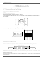
4.1 Communications port and wiring ...................................................................................................210
4.2 Communication mode ....................................................................................................................210
Appendix ............................................................................................................................................................217
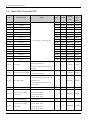
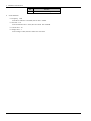
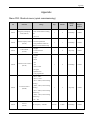
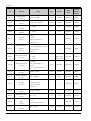
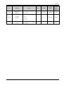
Menu P00: Shortcut menu (quick commissioning) .................................................................................217
Logic diagram contents
Menu 1A Logic diagram ........................................................................................................................................ 6
Menu 1B Logic diagram ........................................................................................................................................ 7
Menu 1C Logic diagram........................................................................................................................................ 7
Menu 2A Logic diagram ...................................................................................................................................... 20
Menu 2B Logic diagram ...................................................................................................................................... 21
Menu 2C Logic diagram...................................................................................................................................... 21
Menu 3 Logic diagram ........................................................................................................................................ 32
Menu 7A Logic diagram ...................................................................................................................................... 69
Menu 7B Logic diagram ...................................................................................................................................... 70
Menu 7C Logic diagram...................................................................................................................................... 71
Menu 8 Logic diagram ........................................................................................................................................ 81
Menu 9 Logic diagram ........................................................................................................................................ 93
Menu 13 Logic diagram .................................................................................................................................... 141
Menu 15A Logic diagram .................................................................................................................................. 161
Menu 15B Logic diagram .................................................................................................................................. 162
Menu 16A Logic diagram .................................................................................................................................. 174
Menu 16B Logic diagram .................................................................................................................................. 174
Menu 17 Logic diagram .................................................................................................................................... 185
Menu 18 Logic diagram .................................................................................................................................... 203
1 Parameter description
1 Parameter description
1.1
Overview
HD700 drive applications are divided into three levels: quick application, the basic application and advanced application.
In order to the user quickly start the drive, HD700 drives design P00 parameters that are related to other function
parameters. Changing one of P00 parameters will cause the related parameter being changed and vice versa. Menu P00
has been described in detail in the HD700 use manual. To avoid a repeat, Menu P00 is not described in this advanced
manual. P00 parameters are only noted behind the name of the related parameters in parentheses.
In the basic applications, the drive preset some functions. The user can use these functions by simple settings. The basic
application functions meet the needs of most cases.
In the advanced applications, the user can program parameters and can select almost all parameters as source parameter or
destination parameter (if the attribute of the parameter is permitted and the parameter does not conflict with other
parameters settings). The drive has internal enhancement module that can realize logic operation, arithmetic operation,
binary-decimal conversion, comparison operation and so on in order to meet the specific function needs of users.
1.2 Parameter attributes description
1.2.1 Parameter description format
In the following sections, descriptions are given for the advanced parameter set. With each parameter the following
information block is given.
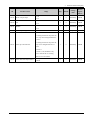
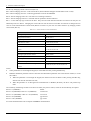
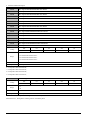
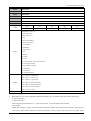
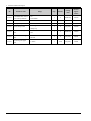
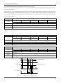
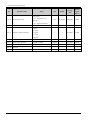
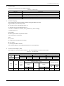
Table 1-1
Parameter ID
Coding
Parameter description format
Parameter name (is related to P00 parameter)
RW
US
PT
ND
PS
Range
Default
Change mode
The top row gives the menu: parameter number and the parameter name.
Coding: The coding defines the attributes of the parameter as follows:
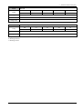
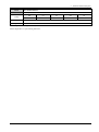
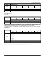
Table 1-2
Parameter attributes description
Coding
Attribute
ND
No default: When defaults are loaded, this parameter is not modified.
PT
Protected: cannot be used as a destination.
US
Users save: saved in drive EEPROM when the user initiates a parameter save.
RW
Read/write: can be written by the user.
PS
Power-down save: parameter automatically saved in drive EEPROM when the under volts (UV) trip occurs.
Range: This gives the range of the parameter and the values it can be adjusted to.
Default: The default values given are the standard drive defaults.
Change mode: to define if the parameter can be modified, and under what condition the user can change the parameter.
Run&Stop: write & read can be done at running and stopping.
HD700 Advanced User Manual
1
1 Parameter description
Stop Only: write & read can be done only at stopping.
Actual: read only
For example:
Table 1-3
P08.02
Analogue input 1 mode (P00.05)
RW
US
PT
■
■
■
Coding
Range
0~6
Default
6
Change mode
Parameter description format
ND
PS
Stop Only
P08.02: Parameter ID
Analogue input 1 mode ( is related to P00.05):Parameter name
Parameter attribute: The parameter can be revised during running and stopping state and saved in drive EEPROM. The
parameter cannot be a destination.
Parameter setting range: 0~6
Default value: 6
Stop Only: Means that the parameter can be revised during stopping.
1.2.2 Parameter type
There are two fundamental types of parameters in the drive, Bit parameters and Non-bit parameters.
Bit parameters are two state only (0 or 1), such as DI1 status (P09.40) and so on.
Non-bit parameters can be further broken down into Integer parameters and Enumeration type parameters.
Integer parameters are the parameters that the value of parameters can be changed continually, such as output frequency,
acceleration/deceleration rate, motor rated current and so on.
Enumeration type parameters provide an option list that each option contains a function mark. Enumeration type
parameters are described as selector parameters in this advanced manual. Some selector parameters have the basic and
advanced application function options. The basic application function options are defined already and they are usually
indicated as numbers. The advanced application function options are programmed by the user, usually given the parameter
setting range.
For example, DI1 function (P09.02), when P09.02 is basic application (P09.01=0), its option list contains 16 function
options. 0 to 15 each digit respectively represents a function. When P09.02 is advanced application (P09.01=1), the
setting range is P01.01 to P18.08 that means the user can define any parameter (if the attribute of the parameter is
permitted and the parameter does not conflict with other parameters settings) from P01.01 to P18.18 as controlled by DI1.
2
HD700 Advanced User Manual
1 Parameter description
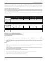
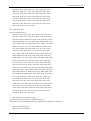
1.2.3 Sources and destinations
Input 1 selector
Pxx.xx
Output selector
P01.01
Pyy.yy
Input 1
P01.01
P18.08
HD700
advanced
application
function
Sources
P01.01
Output
Destinations
Output
P18.08
Input n
P18.08
Pxx.xx
Input n selector
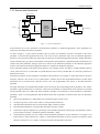
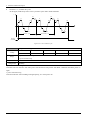
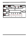
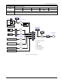
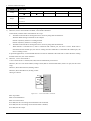
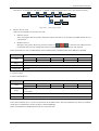
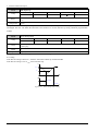
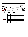
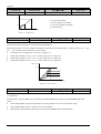
Figure 1-1
Sources and destinations
Some functions have source parameters and destination parameters in advanced applications. These parameters are
respectively selected by the selector parameters.
As show in figure 1-1, input selector parameter (Pxx.xx) selects one parameter of P01.01 to P180.08 as the source
parameter of the advanced application function. The value of source parameter input into the advanced application
functions as the input and produce the output after processed by the advanced application functions. Output destination
selector parameter (Pyy.yy) selects one parameter (if the attribute of the parameter is permitted and the parameter does not
conflict with other parameters settings) of P01.01 to P18.08 as the destination parameter of the advanced application
function. The output of the advanced application function is routed to the destination parameter.
Source parameters usually are the input of these functions. For example, if select AI1 (P08.17) as PID controller reference
source, must set P15.01=8.17 (select P08.17 by PID reference source P15.01), and then P08.17 is the source parameter of
PID reference source.
Destination parameters are the parameters controlled by these functions. For example, if select PID output as the drive
frequency reference, must set P15.15=1.27 (PID output is routed to P01.27-user programmed reference by PID output
destination P15.15) and P01.01=8 (reference source is the user programmed), then P01.27 is the PID destination
parameter.
The input and output of all enhancement modules can be selected by the corresponding selector parameters. The selector
parameters range is P00.00 (P01.01) to P18.08. It means that all parameters (if the attribute of the parameter is permitted
and the parameter does not conflict with other parameters settings) can be selected as source parameters or destination
parameters. There is no actual parameter P00.00. P00.00 means that no parameter is selected as the source or destination
parameter.
If the source parameter (e.g. P00.00) does not exist then the input is taken as zero.
The input is given by (source value x 100%) / source parameter maximum.
If the destination parameter does not exist then the output value has no effect.
If the destination parameter is protected then the output value has no effect.
The function output is displayed as a percentage of the destination parameter setting range. The destination value is
given by (function output × destination parameter maximum) / 100%
The destination parameter will not conflict with the destination parameters of other functions. For example, if set
P16.07 (block 1 output function)=6.11 (P06.11 is the destination parameter of block 1), then P16.14 (block 2 output
function) cannot be set to 6.11 (P06.11 cannot be selected as the destination of block 2).
HD700 Advanced User Manual
3
2 Parameter detailed description
2 Parameter detailed description
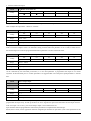
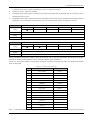
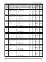
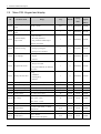
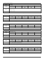
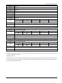
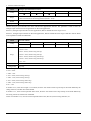
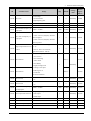
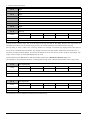
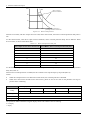
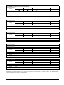
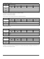
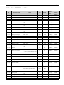
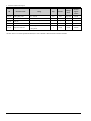
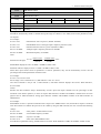
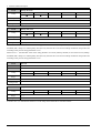
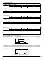
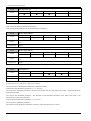
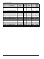
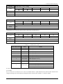
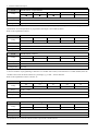
2.1
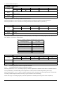
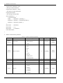
ID
Menu P01: Reference
Parameter name
Range
Step
Default
Change
mode
Modbus
register
address
0: keypad
1: E-pot
2: preset
3: AI1
P01.01
Reference source selector
4: AI2
1
0
Run&Stop
0064H
5: serial comms.
6: DI7 pulse
7: optional card
8: user programmed
P01.02
Maximum frequency
0.00Hz~300.0Hz
0.01Hz
50.00Hz
Stop Only
0065H
P01.03
Minimum frequency
0.00Hz~max. frequency
0.01Hz
0.00Hz
Stop Only
0066H
P01.04
Jog frequency
0.00Hz~P01.02
0.01Hz
5.00Hz
Run&Stop
0067H
P01.05
Skip frequency1
0.00Hz~max. frequency
0.01Hz
0.00Hz
Stop Only
0068H
P01.06
Skip frequency2
0.00Hz~max. frequency
0.01Hz
0.00Hz
Stop Only
0069H
P01.07
Band of skip frequency
0.00Hz~30.00Hz
0.01Hz
0.00Hz
Stop Only
006AH
P01.08
Reserved
−
−
−
−
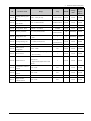
P01.09
Keypad reference display
− max. frequency~+ max. frequency
0.01Hz
Actual
Actual
006CH
P01.10
E-Pot reference display
− max. frequency~+ max. frequency
0.01Hz
Actual
Actual
006DH
1
0
Run&Stop
006EH
−
0: 0.00Hz
P01.11
Power up Keypad reference
1: running reference when last power off
2: preset1
4
P01.12
Threshold of zero speed
0.00Hz~max. frequency
0.01Hz
0.50Hz
Run&Stop
006FH
P01.13
Band of frequency arrival
0.00Hz~max. frequency
0.01Hz
2.50Hz
Run&Stop
0070H
P01.14
Setup reference display
− max. frequency~300.0Hz
0.01Hz
Actual
Actual
0071H
P01.15
Preset select bit0 status
1
Actual
Actual
0072H
P01.16
Preset select bit1 status
1
Actual
Actual
0073H
P01.17
Preset select bit2 status
1
Actual
Actual
0074H
P01.18
Preset select bit3 status
1
Actual
Actual
0075H
P01.19
Preset select indicator
Preset 1~Preset 16
1
Actual
Actual
0076H
P01.20
AI1 reference display
− max. frequency~+ max. frequency
0.01Hz
Actual
Actual
0077H
0: on
1: off
0: on
1: off
0: on
1: off
0: on
1: off
HD700 Advanced User Manual
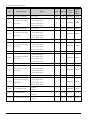
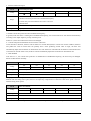
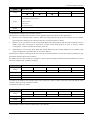
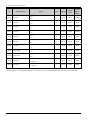
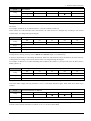
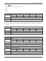
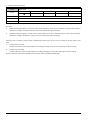
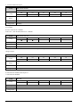
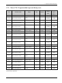
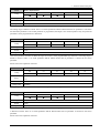
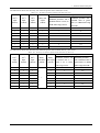
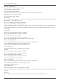
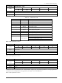
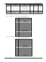
2 Parameter detailed description
ID
Parameter name
P01.21
AI2 reference display
P01.22
RUN/Stop indicator
P01.23
Frequency arrival indicator
P01.24
Zero speed indicator
P01.25
P01.26
P01.27
P01.28
P01.29
P01.30
Range
− max. frequency~+ max. frequency
0078H
1
Actual
Actual
0079H
1
Actual
Actual
007AH
1
Actual
Actual
007BH
1
Actual
Actual
007CH
1
Actual
Actual
007DH
− max. frequency~+ max. frequency
0.01Hz
Actual
Actual
007EH
0.00Hz~P01.02
0.01Hz
0.00Hz
Run&Stop
007FH
0.00Hz~P01.28
0.01Hz
0.00Hz
Run&Stop
0080H
1
0
Actual
0080H
0: Stop is active
1: Run is active
0: not arrival
1: arrival
0: none zero speed
1: at zero speed running
1: on
Reference source is
0: off
switched to AI2
1: on
(FDT) threshold
Output frequency detection
(FDT) width
register
address
Actual
0: off
Output frequency detection
mode
Actual
switched to AI1
display
Default
Modbus
0.01Hz
Reference source is
User programmed reference
Step
Change
Output frequency detection
0: off
(FDT) indicator
1: on
HD700 Advanced User Manual
5
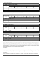
2 Parameter detailed description
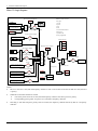
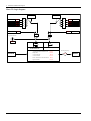
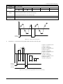
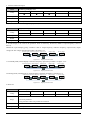
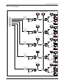
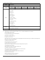
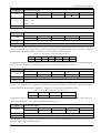
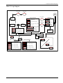
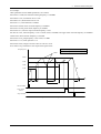
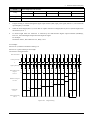
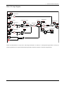
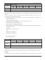
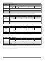
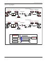
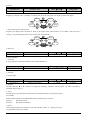
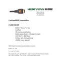
Menu 1A Logic diagram
Reference source selector:
Power up keypad reference
0: keypad
P01.11
0.00Hz
1: E-port
2: preset
0
1
2
The last time power off
keypad reference
3: AI1
P01.09
4: AI2
Preset 1
5: serial communications
Keypad reference display
6: DI7 pulse
P04.01
7: optional card
E-port reference display
E-port
8: user programmed
P01.10
Preset select bit
Menu 1C
P01.18
Preset speed reference
or
Reference source selector
P01.01
AI1 reference display
AI1
AI2
P01.20
M
E
N AI2 reference display
U
8
P01.21
Preset 1
Serial communications
P01.17
P01.16
P01.15
0
1
2
3
4
5
6
7
8
or
P01.26
P01.25
Setup reference display
0
0
1
P01.14
1
Menu 1B
P04.01
Preset priority
Switch to AI1/AI2
DI7 level of input frequency
DI7 pulse
P09.38
User programmed reference display
User programmed
……
Optional card
Analogue
reference
P04.02
Preset
P04.16
Menu 1C
P01.20
P01.21
P01.27
NOTE:
P01.25 or P01.26 is valid, then the frequency switches to AI1 or AI2. If P01.25 and P01.26 both are valid, then AI1
is priority.
When P01.25 and P01.26 both are invalid:
One of the preset select bits is valid, then the frequency reference switches to preset in priority.
6
Corresponding preset (preset 2 to preset 16) is selected as frequency reference.
Switching to AI1/AI2 and preset priority both are invalid, the frequency channel selected by P01.01 is frequency
reference.
HD700 Advanced User Manual
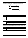
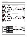
2 Parameter detailed description
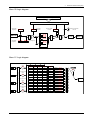
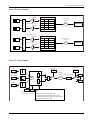
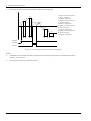
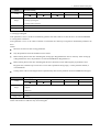
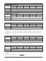
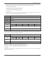
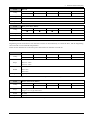
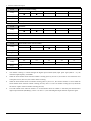
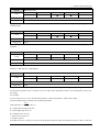
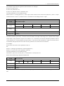
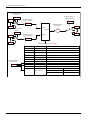
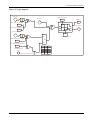
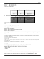
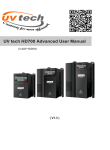
Menu 1B Logic diagram
MENU 9 Digital input and output terminals
Start and stop logic
Maximum
frequency
P01.02
P02.18
Jog select
indicator
Reverse limit
control
Run/stop indicator
P01.22
P03.01
0
+
Menu 1A
0
1
−
Minimum
frequency
P01.03
+
P01.04 Jog frequency
P01.02
P01.03
P01.03
P01.02
0
1
0
1
Skip
frequency
Menu 2
P01.02
P01.03
−
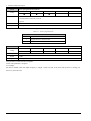
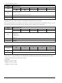
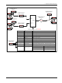
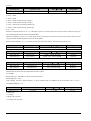
Menu 1C Logic diagram
Preset select bit0
status
P01.15
MENU9 Digital input
Preset select bit1
status
P01.16
Preset select bit2
status
P01.17
Preset select bit3
status
P01.18
P01.18
P01.17
P01.16
P01.15
P01.19
0
0
0
0
1
Preset1
(P04.01)
1
0
0
0
1
2
Preset2
(P04.02)
2
0
0
1
0
3
Preset3 (P04.03)
3
0
0
1
1
4
Preset4 (P04.04)
4
0
1
0
0
5
Preset5 (P04.05)
5
0
1
0
1
6
Preset6 (P04.06)
6
0
1
1
0
7
Preset7 (P04.07)
7
0
1
1
1
8
Preset8 (P04.08)
8
1
0
0
0
9
Preset9 (P04.09)
9
1
0
0
1
10
Preset10 (P04.10)
10
1
0
1
0
11
Preset11 (P04.11)
11
1
0
1
1
12
Preset12 (P04.12)
12
1
1
0
0
13
Preset13 (P04.13)
13
1
1
0
1
14
Preset14 (P04.14)
14
1
1
1
0
15
Preset15 (P04.15)
15
1
1
1
1
16
Preset16 (P04.16)
16
HD700 Advanced User Manual
多段速选择值
P01.19
Menu 1A
7
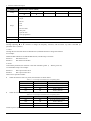
2 Parameter detailed description
P01.01
Reference source selector (P00.04)
RW
US
■
■
Coding
PT
ND
PS
0: keypad
1: E-pot
2: Preset
3: AI1
Range
4: AI2
5: Serial comms.
6: DI7 pulse
7: optional card
8: User-programmed
Default
Change mode
0
Run&Stop
0: Keypad
Through adjusting ▲ or ▼ switches to change the frequency reference, and the Power up value is decided by
parameter P01.11 (P00.12).
1: E-Pot
Through the two terminals which are defined as UP, DOWN function to change the reference.
For example:
Define the DI4 and DI5 as UP and DOWN function, and the setup is as below:
P09.05=8
DI4 function is UP
P09.06=9
DI5 function is DOWN
2: Preset
Controlled by terminals, the reference is the value of P04.01 (preset 1)
~P04.16 (preset
16).
Use the default setup as an example:
P09.05=0
DI4 is preset select bit 0
P09.06=1
DI5 is preset select bit 1
There are tow operation modes:
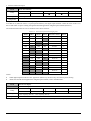
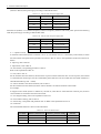
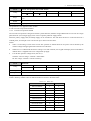
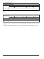
When the reference source is preset, terminal status as shown below:
Table 2-1-1
Preset and preset terminal status corresponding table 1
DI5 Status (bit 1)
DI4 Status (bit 0)
Speed
OFF
OFF
Preset 1 (P04.01)
OFF
ON
Preset 2 (P04.02)
ON
OFF
Preset 3 (P04.03)
ON
ON
Preset 4 (P04.04)
When the reference source is not preset, terminal status as shown below:
Table 2-1-2
Preset and preset terminal status corresponding table 2
DI5 Status (bit 1)
DI4 Status (bit 0)
Speed
OFF
OFF
Keep the frequency setting
OFF
ON
Preset 2 (P04.02)
ON
OFF
Preset 3 (P04.03)
ON
ON
Preset 4 (P04.04)
About 16 presets (P04.01~P04.16) control, please refer to Menu P04.
8
HD700 Advanced User Manual
2 Parameter detailed description
3: AI1
In this mode, frequency reference can be adjusted by changing the value of analogue input1.
About AI1 signal mode, there are current mode and voltage mode, details please refer to the explanation of parameter
P08.02.
4: AI2
In this mode, frequency reference can be adjusted by changing the value of analogue input2.
AI2 has only voltage mode.
AI2 detail setup please refers to Menu P08.
5: Serial comms.
Under this mode, users can change the value of P04.01 (Preset1) for the reference. Details please refer to chapter 4
Communication.
6: DI7 Pulse input
In this mode, the frequency can be adjusted by the external pulse counter of DI7.
When P09.24=2, DI7 function is reference channel (by input pulse).
For example:
The maximum frequency of input pulse (P09.27) is 20.0kHz. the actual input pulse is 10.0kHz.
The percentage of DI7 pulse input (P09.38) is 50.0%. Then the reference is:
Reference = DI7 input percentage (P09.38) × maximum reference (P01.02)
= 50.0% × 50.00Hz
= 25.00Hz
Details please refer to Menu P09.
7: Optional card (By option modules)
By option modules. The HD700 drives which software version of control board is 1.04 and above support
HDOM-Profibus-V0 bus module.
8: User-programmed
By destination and source control, the user can define the reference channel freely.
For example, through Menu P17, the user can define the reference source. About actual application guide, please refer to
the Menu P15, Menu P17 and the explanation of parameter P01.27.
P01.02
Maximum frequency (P00.07)
RW
US
■
■
Coding
Range
0.00Hz~300.0Hz
Default
50.00Hz
Change mode
PT
ND
PS
Stop Only
This parameter is used to define drive absolute maximum frequency reference.
HD700 Advanced User Manual
9
2 Parameter detailed description
P01.03
Minimum frequency (P00.08)
RW
US
■
■
Coding
Range
0.00Hz~maximum frequency
Default
0.00Hz
Change mode
PT
ND
PS
PT
ND
PS
PT
ND
PS
PT
ND
PS
Stop Only
This parameter is used to define drive minimum frequency reference.
If P03.01=0 (reverse is enabled), then the P00.08 is fixed at 0.00Hz.
P01.04
Jog frequency
RW
US
■
■
Coding
Range
0.00Hz~P01.02
Default
5.00Hz
Change mode
Run&Stop
This parameter is used to define drive jogging frequency reference.
P01.05
Skip frequency 1
P01.06
Skip frequency 2
Coding
RW
US
■
■
Range
0.00Hz~maximum frequency
Default
0.00Hz
Change mode
P01.07
Stop Only
Band of skip frequency
Coding
RW
US
■
■
Range
0.00Hz~30.00Hz
Default
0.00Hz
Change mode
Stop Only
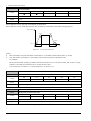
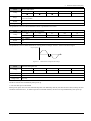
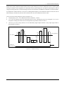
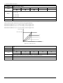
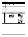
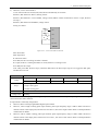
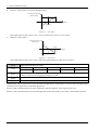
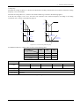
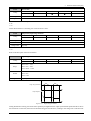
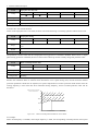
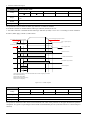
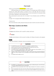
Two skip references are available to prevent continuous operation at a speed that would cause mechanical resonance.
When a skip reference parameter is set to 0, filter is disabled. The skip reference band parameters define the frequency or
speed range either side of the programmed skip reference, over which reference are rejected. The actual reject band is
therefore twice that programmed in these parameters, the skip reference parameters defining the centre of the band. When
the selected reference is within a band, the lower limit value of the band is the last reference. The last reference is limited
among minimum frequency (P01.03) to maximum frequency (P01.02).
For example 1:
P01.02=50.00Hz, P01.03=0.00Hz, P01.05=2.00Hz, P01.06=5.00Hz, P01.07=1.00Hz. (Other parameters with default).
When the given frequency is among 1.00Hz to 3.00Hz, the last frequency is 1.00Hz. When the given frequency is among
4.00Hz to 6.00Hz, the last frequency is 4.00Hz. The frequency out of skip reference band is not changed.
For example 2:
P01.02=50.00Hz, P01.03=0.10Hz, P01.05=2.00Hz, P01.06=48.00Hz., P01.07=3.0Hz. (Other parameters with default)
10
HD700 Advanced User Manual
2 Parameter detailed description
When the given frequency is among 0.00Hz to5.00Hz, the last frequency is 0.10Hz.When the given frequency is among
45.00Hz to 50.00Hz, the last frequency is 45.00Hz. The frequency out of skip reference band is not changed.
f
Band of skip
frequency
Skip frequency 1
P01.07
P01.06
P01.07
Band of skip
frequency
Skip frequency 2
P01.07
P01.05
P01.07
t
Figure 2-1-1
Skip frequency example
NOTE:
The drive output frequency can pass through band of skip frequency during acceleration and deceleration.
Do not overlap two skip reference bands.
P01.08
Reserved
RW
Coding
US
PT
ND
PS
US
PT
ND
PS
Range
Default
Change mode
P01.09
Keypad reference display
RW
Coding
Range
Change mode
■
■
− max. frequency (P01.02)~+ max. frequency (P01.02)
Actual
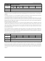
This parameter is the reference used when digital reference1 is selected.
When P01.01=0, the reference value can be changed with UP or Down key in the status mode (excluding fault occurs).
P01.09 has no negative frequency display in the non reverse mode.
P01.10
E-pot reference display
RW
Coding
Range
Change mode
US
PT
ND
PS
■
■
− max. frequency (P01.02)~+ max. frequency (P01.02)
Actual
This parameter is the reference used when the UP\DOWN terminals reference is selected.
P01.10 has no negative frequency display in the non reverse mode.
HD700 Advanced User Manual
11
2 Parameter detailed description
P01.11
Power up keypad reference (P00.12)
Coding
Range
RW
US
PT
■
■
■
ND
PS
0: 0.00Hz
1: running reference when last power off
2: preset1
Default
Change mode
0
Run&Stop
The parameter is used to select the value of the keypad reference on power up.
Table 2-1-3
Power up keypad reference
P01.11=
P01.12
Function
0
Keypad reference is zero.
1
Keypad reference is last used value.
2
Keypad reference is copied from Preset speed1 (P04.01)
Threshold of zero speed
Coding
RW
US
PT
■
■
■
Range
0.00Hz~maximum frequency (P01.02)
Default
0.50Hz
Change mode
ND
PS
Run&Stop
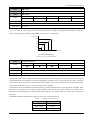
This parameter is used with P01.24 together.
NOTE: This parameter is nonpolar.
For example:
Set P01.12=0.50Hz, when the output frequency is ranged −0.5Hz to 0.5Hz, at the same time the drive is running (I.E.
P05.27=1), then P01.24=1.
12
HD700 Advanced User Manual
2 Parameter detailed description
P01.13
Band of frequency arrival
Coding
RW
US
PT
■
■
■
Range
0.00Hz~maximum frequency (P01.02)
Default
2.50Hz
Change mode
ND
PS
Run&Stop
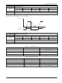
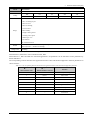
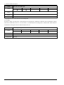
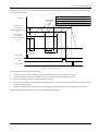
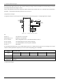
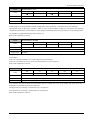
This parameter is supplementary define of P01.23. As figure shown below, when output frequency of drive is in the error,
then P01.23=1.
f
P 01. 13
Setup reference display P 01. 14
P 01. 13
t
Frequency arrival indicator P 01. 23
Figure 2-1-2
P01.14
Setup reference display
RW
Coding
Range
Change mode
Error of at speed example
US
PT
ND
■
■
PS
− max. frequency (P01.02)~+ max. frequency (P01.02)
Actual
This parameter is used to define drive setting frequency.
P01.15
Preset select bit0 status
P01.16
Preset select bit1 status
P01.17
Preset select bit2 status
P01.18
Preset select bit3 status
RW
US
PT
Coding
Range
Change mode
ND
PS
■
0~1
Actual
HD700 Advanced User Manual
13
2 Parameter detailed description
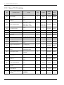
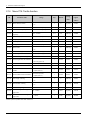
P01.19
Preset select indicator
RW
US
Coding
Range
Change mode
PT
ND
■
■
PS
preset1~preset16
Actual
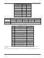
This parameter is used to select the actual preset speed reference.
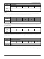
If set P01.01=2 (reference source is a preset speed reference), the digital input terminals control the value of P01.15 to
P01.19 and realize 16-preset running through the advanced application of digital input terminals (P09.01=1).
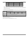
The relations between P01.15 to 01.18 and P01.19 are shown as below:
Table 2-1-4
Preset and the preset terminal mapping table
P01.18
P01.17
P01.16
P01.15
Reference selector
P01.19
OFF
OFF
OFF
OFF
Preset1
1
OFF
OFF
OFF
ON
Preset2
2
OFF
OFF
ON
OFF
Preset3
3
OFF
OFF
ON
ON
Preset4
4
OFF
ON
OFF
OFF
Preset5
5
OFF
ON
OFF
ON
Preset6
6
OFF
ON
ON
OFF
Preset7
7
OFF
ON
ON
ON
Preset8
8
ON
OFF
OFF
OFF
Preset9
9
ON
OFF
OFF
ON
Preset10
10
ON
OFF
ON
OFF
Preset11
11
ON
OFF
ON
ON
Preset12
12
ON
ON
OFF
OFF
Preset13
13
ON
ON
OFF
ON
Preset14
14
ON
ON
ON
OFF
Preset15
15
ON
ON
ON
ON
Preset16
16
NOTE:
When digital input terminals are basic application (P09.01=0), the drive only can realize 4-preset running.
About basic and advanced applications of digital input terminals, refer to the Menu P09.
P01.20
AI1 reference display
P01.21
AI2 reference display
RW
US
PT
Coding
Range
Change mode
ND
PS
■
− max. frequency (P01.02)~+ max. frequency (P01.02)
Actual
These parameters are made available for control by analogue inputs that are required to be frequency references.
14
HD700 Advanced User Manual
2 Parameter detailed description
P01.22
RUN/STOP indicator
RW
US
Coding
Range
Change mode
PT
ND
■
■
PS
0: Stop is active
1: Run is active
Actual
The parameter indicates that the drive is in running or stopping status.
NOTE:
This parameter indicates whether RUN/STOP Command is valid, it cannot indicate the work status of the drive.
In ramp stop mode, P01.22=0, while P05.27 (indicates the work status of the drive) =1.
P01.23
Frequency arrival indicator
RW
US
Coding
Range
Change mode
PT
ND
■
■
PS
0~1
Actual
When running reference (P05.11) = setup reference (P01.14), P01.23=1.
NOTE: This parameter is used with P01.03 (band of frequency arrival) together. Details please refer to the explanation of
the parameter P01.03.
P01.24
Zero speed indicator
RW
US
Coding
Range
Change mode
PT
ND
■
■
PS
0~1
Actual
Indication of the zero speed operation status of the drive.
This parameter is used with P01.12 (threshold of zero speed) together. Details please refer to the explanation of the
parameter P01.12.
P01.25
Reference source is switched to AI1
P01.26
Reference source is switched to AI2
RW
Coding
Range
Change mode
US
PT
ND
PS
■
0~1
Actual
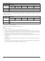
These parameters are made available for control by analogue inputs that are required to be frequency references. With
these parameters, main speed source can be quickly set to AI1 or AI2 by corresponding terminal operation. Either P01.25
or P01.26 can be valid at the same time. That is both P01.25 and P01.26 are valid controlled by different digital input
terminal. The condition is not allowed. If it occurs, the following priority level is run. P01.25 > P01.26 > P01.01.
HD700 Advanced User Manual
15
2 Parameter detailed description
Assumed that:
P01.01=0 (Speed source given by keypad)
P09.01=1 (Digital terminal in programmable mode)
P09.02=1.25 (DI1 controls that main speed source switch to AI1)
P09.03=1.26 (DI1 controls that main speed source switch to AI1)
The following table shows the corresponding condition:
Table 2-1-5
P01.27
Reference source is switched to AI1
P01.01=
DI1
DI2
P01.14 (setup reference)
0
OFF
OFF
=P01.09 (keypad)
0
OFF
ON
=P01.21 (AI2)
0
ON
OFF
=P01.20 (AI1)
0
ON
ON
=P01.20 (AI1)
User-programmed reference display
RW
US
PT
Coding
Range
Change mode
ND
PS
■
− maximum frequency~+ maximum frequency
Actual
Select this function when main and auxiliary reference is needed.
If set P01.01=8, reference source is connected with this parameter (see Menu 1A Logic diagram). It is flexible for the user
to program reference source by using this parameter. P01.27 is assigned after the various enhance function blocks process
reference, realizing the user specific needs.
For example:
In the main and auxiliary reference applications, the keypad reference (P01.09) is the main reference and preset 1 (P04.01)
is the auxiliary reference. In order to realize setup reference (P01.14) = keypad reference (P01.09) + preset 1 (P04.01), the
user can make the following settings:
P17.11=1.09, operation module 1 input 1 source is keypad reference.
P17.12=4.01, operation module 1 input 2 source is preset 1.
P17.17=1.27, the value of operation module 1 output is given to P01.27 (select P01.27 by using P17.17)
P17.15=2, operation module 1 mode is input 1 + input 2
P01.01=8, setup reference (P01.14)=user programmed reference (P01.27)
Refer to Menu P17 for details.
P01.28
Output frequency detection (FDT) threshold
Coding
US
■
■
Range
0.00Hz~P01.02
Default
0.00Hz
Change mode
16
RW
PT
Run&Stop
HD700 Advanced User Manual
ND
PS
2 Parameter detailed description
P01.29
Output frequency detection (FDT) width
Coding
RW
US
■
■
Range
0.00Hz~P01.28
Default
0.00Hz
Change mode
P01.30
PT
ND
PS
PT
ND
PS
■
■
Run&Stop
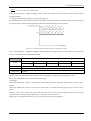
Output frequency detection (FDT) indicator
RW
US
Coding
Range
0: off
1: on
Change mode
Actual
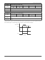
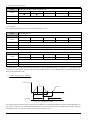
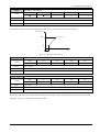
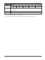
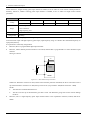
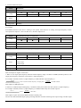
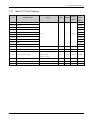
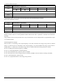
If the absolute value of P05.11 (output frequency) is more than or equal to the value of P01.28 adding P01.29, output
frequency detection signal is valid. If the absolute value of P05.11 (output frequency) is less than or equal to the value of
P01.28 subtracting P01.29, output frequency detection signal is invalid. As shown in the figure:
F
(Output Freqency)
P01.29
P01.28
P01.29
T
P01.30
Figure 2-1-3
FDT
HD700 Advanced User Manual
17
2 Parameter detailed description
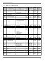
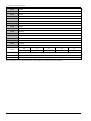
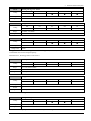
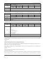
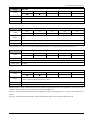
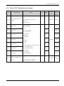
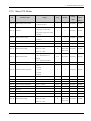
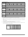
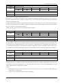
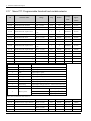
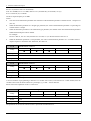
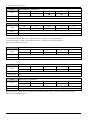
2.2
Menu P02: Ramp
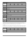
ID
P02.01
Parameter name
Range
Acceleration and deceleration
0: line
mode
1: S curve
0: off
Step
Default
Change
mode
Modbus
register
address
1
0
Stop Only
00C8H
1
0
Run&Stop
00C9H
−
−
−
−
P02.02
Ramp hold
P02.03
Reserved
−
P02.04
Accel. rate1
0.0~3600.0
0.1
10.0
Run&Stop
00CBH
P02.05
Decel. rate1
0.0~3600.0
0.1
20.0
Run&Stop
00CCH
P02.06
Accel. Rate2
0.0~3600.0
0.1
30.0
Run&Stop
00CDH
P02.07
Decel. Rate2
0.0~3600.0
0.1
30.0
Run&Stop
00CEH
P02.08
Accel. Rate3
0.0~3600.0
0.1
30.0
Run&Stop
00CFH
P02.09
Decel. Rate3
0.0~3600.0
0.1
30.0
Run&Stop
00D0H
P02.10
Accel. Rate4
0.0~3600.0
0.1
30.0
Run&Stop
00D1H
P02.11
Decel. Rate4
0.0~3600.0
0.1
30.0
Run&Stop
00D2H
P02.12
S curve start time
0.0%~40.0%
0.1%
20.0%
Run&Stop
00D3H
P02.13
S curve finish time
0.0%~40.0%
0.1%
20.0%
Run&Stop
00D4H
Acceleration rate selector bit0
0: off
status
1: on
1
Actual
Actual
00D5H
Acceleration rate selector bit1
0: off
status
1: on
1
Actual
Actual
00D6H
Deceleration rate selector bit0
0: off
status
1: on
1
Actual
Actual
00D7H
Deceleration rate selector bit1
0: off
status
1: on
1
Actual
Actual
00D8H
1
Actual
Actual
00D9H
P02.14
P02.15
P02.16
P02.17
1: on
0: off
P02.18
Jog select indicator
P02.19
Accel. Rate select indicator
Accel. rate1~Accel. rate 4
1
Actual
Actual
00DAH
P02.20
Decel. Rate select indicator
Decel. rate1~Decel. rate 4
1
Actual
Actual
00DBH
Accel. Rate & Decel. Rate unit
0: second
selector
1: minute
1
0
Stop Only
00DCH
P02.22
Jog Accel. rate
0.1s~600.0s
0.1s
10.0s
Run&Stop
00DDH
P02.23
Jog Decel. rate
0.1s~600.0s
0.1s
10.0s
Run&Stop
00DEH
P02.24
Jog interval time
0.1s~600.0s
0.1s
1.0s
Run&Stop
00DFH
P02.25
E-Pot output negative permit
1
0
Run&Stop
00E0H
P02.26
UP/DN Accel. rate
0s~250s
1s
10s
Run&Stop
00E1H
P02.27
E-pot output scaling
0.000~4.000
0.001
1.000
Run&Stop
00E2H
P02.28
Function selector of E-pot output
P01.01~P18.08
0.01
P01.10
Stop Only
00E3H
P02.21
18
1: on
0: only positive
1: negative permit
HD700 Advanced User Manual
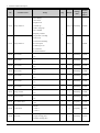
2 Parameter detailed description
ID
Parameter name
P02.29
Reset of E-pot output
P02.30
UP
P02.31
DOWN
P02.32
E-Pot output display
Range
0: off
1: on
0: off
1: on
0: off
1: on
−100.0%~+100.0%
Step
Default
Change
mode
Modbus
register
address
1
0
Run&Stop
00E4H
1
0
Run&Stop
00E5H
1
0
Run&Stop
00E6H
0.1%
Actual
Stop Only
00E7H
1
0
Run&Stop
00E8H
1
0
Run&Stop
00E9H
0: 0
1: running reference at last power off
2: 0, only can be changed when drive
is active
3: running reference at last power off,
P02.33
Power up E-Pot reference
only can be changed when drive is
active
4: Preset 1
5: Preset 1, UP, DOWN are only
active when the drive is running.
Reset is active at all times.
P02.34
Power off E-Pot output selector
0: Keep
1: Reset
HD700 Advanced User Manual
19
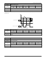
2 Parameter detailed description
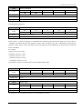
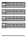
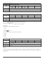
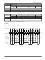
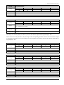
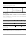
Menu 2A Logic diagram
Menu2B
Accel. Rate 1
P02.04
Accel. Rate 2
P02.06
Accel. Rate 3
P02.08
Accel. Rate 4
P02.10
Jog accel. rate
Menu2B
1
2
3
4
1
2
3
4
P02.05
Decel. Rate 1
P02.07
Decel. Rate 2
P02.09
Decel. Rate 3
P02.11
Decel. Rate 4
P02.23
P02.22
1 0
Jog select indicator
Jog decel. rate
1 0
P02.18
N
t
Acceleration rate
Menu1B
N
t
Deceleration rate
Acceleration and deceleration mode
P02.01
Ramp hold
P02.02
S curve start time
P02.12
S curve end time
P02.13
Accel. rate and decel. rate unit selector P02.21
Jog interval time
20
P02.24
HD700 Advanced User Manual
Running frequency
P05.11
Menu3
2 Parameter detailed description
Menu 2B Logic diagram
Accel. rate selector bit 0
Digital input terminal
P02.14
M
e
n
u
P02.14
P02.15
P02.19
0
0
1
0
1
2
1
0
3
1
1
4
P02.16
P02.17
P02.20
0
0
1
Decel. rate selector bit 1
0
1
2
P02.17
1
0
3
1
1
4
Accel. rate selector bit 1
P02.15
Accel. rate select
indicator
Menu2A
P02.19
9
Digital input terminal
Decel. rate selector bit 0
P02.16
M
e
n
u
Decel. rate select
indicator
Menu2A
P02.20
9
Menu 2C Logic diagram
UP
E-pot output
negative permit
Function selector
of E-port output
P02.30
P02.25
P02.28
E-pot output
display
E-pot output scaling
UP/DOWN
acceleration rate
P02.26
M
0
1
P02.32
P01.01
P02.27
P18.08
DOWN
P02.31
P02.34 P02.29 P02.33
Power off E-Pot Reset of E- 0: 0
output selector pot output 1: running reference at last power off
2: 0, only can be changed when drive is active
3: running reference at last power off, only can be
changed when drive is active
HD700 Advanced User Manual
21
2 Parameter detailed description
P02.01
Acceleration and deceleration mode
Coding
Range
Default
Change mode
RW
US
■
■
PT
ND
PS
0: line
1: S curve
0
Stop Only
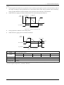
This parameter is used to select the Acceleration/Deceleration mode.
0: Standard ramp (linear)
Output frequency increase or decrease in accordance with a linear ramp.
Output frequency
fmax
t1
Figure 2-2-1
t2
Time
Standard ramp (linear)
1: S curve
Output frequency increase or decrease in accordance with an S curve.
Output frequency
t1
Figure 2-2-2
t2
Time
S curve
When the acceleration is starting or the speed is arriving and the deceleration is starting or the speed is arriving, set the S
ramp mode. It makes the acceleration and the deceleration smooth and reduces the shock. It fits for the starting and
stopping when transfers the load, like the elevator, belt and so on.
P02.02
Ramp hold
Coding
Range
Default
Change mode
RW
US
■
■
PT
ND
PS
0: off
1: on
0
Run&Stop
If this bit is set the ramp will be held. If S ramp is enabled the acceleration will ramp towards zero causing the ramp
output to curve towards a constant speed. If a drive stop is demanded, the ramp hold function is disabled.
22
HD700 Advanced User Manual
2 Parameter detailed description
P02.03
Reserved
RW
US
PT
ND
PS
RW
US
PT
ND
PS
■
■
PT
ND
PS
Coding
Range
Change mode
P02.04
Acceleration rate 1 (P00.09)
P02.06
Acceleration rate 2
P02.08
Acceleration rate 3
P02.10
Acceleration rate 4
Coding
Range
0.0~3600.0
Default
10.0, 30.0, 30.0, 30.0
Change mode
Run&Stop
P02.05
Deceleration rate 1 (P00.10)
P02.07
Deceleration rate 2
P02.09
Deceleration rate 3
P02.11
Deceleration rate 4
Coding
RW
US
■
■
Range
0.0~3600.0
Default
20.0, 30.0, 30.0, 30.0
Change mode
Run&Stop
Acceleration rate is that the drive frequency accelerates from 0Hz to maximum operating frequency (P01.02) time.
Deceleration rate is that the drive frequency decelerates from maximum operating frequency (P01.02) to 0Hz time.
HD700 series drive has defined four acceleration/deceleration rates, it can be selected through different combinations of
the control terminals. Please refer to the explanation of parameters P02.14 to P02.17 for detail.
For example:
Set maximum frequency (P01.02)=50.00Hz, minimum frequency (P01.03)=5.00Hz, setup frequency (P01.14)=10.0s, then
the acceleration rate is 10.0s×(25.00Hz/50.00Hz) =5.0s. The keypad displays 0.00Hz to 25.00Hz, not 5.00Hz to 25.00Hz.
P02.12
S curve start time
Coding
RW
US
■
■
Range
0.0%~40.0%
Default
20.0%
Change mode
PT
ND
PS
Run&Stop
HD700 Advanced User Manual
23
2 Parameter detailed description
P02.13
S curve finish time
Coding
RW
US
■
■
Range
0.0%~40.0%
Default
20.0%
Change mode
PT
ND
PS
Run&Stop
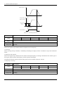
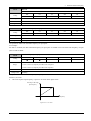
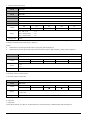
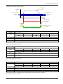
P02.12 indicates S curve start time in acceleration or deceleration.
P02.13 indicates S curve finish time when the drive accelerates or decelerates to the stable running frequency.
Output frequency
P02.13
P02.12
P02.13
P02.12
t2
t1
Figure 2-2-3
Time
S curve start and finish time
NOTE:
P02.12 and P02.13 only become effective when P02.01=1, and make sure that P02.12+P02.13 ≤ 90.0%.
The value of P02.12 and P02.13 is a percentage of the actual acceleration or deceleration rate.
For example:
P01.02 (the maximum frequency)=50.00Hz, P02.04 (acceleration rate 1)=10s, P02.12=20%, P02.13=30%, if setup
reference is 25.00Hz, the acceleration rate is 5s after the drive starts.
S curve start time=5s×20.0%=1s, S curve finish time=5s×30.0%=1.5s.
P02.14
Acceleration rate selector bit0 status
P02.15
Acceleration rate selector bit1 status
RW
US
PT
ND
PS
PT
ND
PS
Coding
Range
Change mode
0~1
Actual
P02.16
Deceleration rate selector bit0 status
P02.17
Deceleration rate selector bit1 status
RW
US
Coding
Range
Change mode
0~1
Actual
P02.14 to P02.17, these bits are for control by logic inputs such that ramp rates can be selected by external control.
24
HD700 Advanced User Manual
2 Parameter detailed description
P02.18
Jog select indicator
RW
US
PT
Coding
Range
Change mode
ND
PS
■
0~1
Actual
This parameter indicates that if jog is effective.
P02.18=0, jog is disable; P02.18=1, jog is enabled.
Output frequency
f
Time
P02.18
Jog select indicator
Figure 2-2-4
P02.19
Acceleration rate select indicator
P02.20
Deceleration rate select indicator
RW
Jog running
US
Coding
Range
Change mode
PT
ND
■
■
PS
1~4
Actual
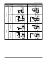
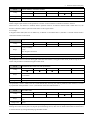
These parameters indicate the acceleration and deceleration time being selected, it is controlled by P02.14 to P02.17.
Table 2-2-1
Acceleration rate selector
P2.15 (Accel. rate selector bit1 status)
P2.14 (Accel. rate selector bit0 status)
P02.19 (Accel. rate select indicator)
0
0
1 (Accel. rate1 P2.04)
0
1
2 (Accel. rate 2 P2.06)
1
0
3 (Accel. rate 3 P2.08)
1
1
4 (Accel. rate 4 P2.10)
Table 2-2-2
Deceleration rate selector
P2.17 (Decel. rate selector bit1)
P2.16 (Decel. rate selector bit0)
P02.20 (Decel. rate select indicator)
0
0
1 (Decel. rate1 P2.05)
0
1
2 (Decel. rate12 P2.07)
1
0
3 (Decel. rate13 P2.09)
1
1
4 (Decel. rate14 P2.11)
HD700 Advanced User Manual
25
2 Parameter detailed description
P02.21
Acceleration and deceleration rate unit selector
Coding
Range
0~1
Default
0
Change mode
RW
US
■
■
PT
ND
PS
PT
ND
PS
PT
ND
PS
Stop Only
0: s (second)
1: m (minute)
This parameter defines the unit of acceleration and deceleration rate 1 to 4.
P02.22
Jog acceleration rate
P02.23
Jog deceleration rate
Coding
RW
US
■
■
Range
0.1~600.0
Default
10.0
Change mode
P02.24
Run&Stop
Jog interval time
Coding
RW
US
■
■
Range
0.1s~600.0s
Default
0.1s
Change mode
Run&Stop
As figure shown, t1 is the jog acceleration rate and t3 is the jog deceleration rate, t2 is jog time; t4 is jog interval time
(P02.24), f1 is jog frequency (P01.04). The actual jog acceleration rate t1 can be determined by the following formula. So
does the jog deceleration rate t3.
t1 =
P01.04 (Jog frequency) × P02.22
P01.02 (Maximum frequency)
Output frequency
f1
t1
t2
t3
Time
t4
Jog command
Figure 2-2-5
Jog parameter explain
The jog interval time (P02.24) is the waiting time from the last jog command cancelling to the next command effecting. In
the jog interval time, the jog command cannot make the drive run, and the drive will run at 0Hz without output. If the jog
command keeping, it will be executed as soon as the interval time is over.
26
HD700 Advanced User Manual
2 Parameter detailed description
NOTE:
In the keypad control mode, the jog operation can be realized by pressing the key MF. Loosen the MF key and the
drive stops according to the stop mode P03.10. In the terminal control mode, the jog operation can be realized by
setting jog FWD and REV terminals. Besides, the jog operation can be realized by communication.
When the drive is jogging, acceleration/deceleration rate is determined by P02.22/P02.23.
Output
frequency
Jog acceleration
rate
Jog deceleration
rate
f
Time
Jog command
Jog interval time
Figure 2-2-6
Jog accel. rate and decel. rate
The jog operation is effective in not-running mode.
When the drive is jogging, the run command is disabled.
Output
frequency
f
Jog frequency
Time
Run command
Jog command
Figure 2-2-7
P02.25
E-Pot output negative permit
Coding
Range
0~1
Default
0
Change mode
Jog command
RW
US
■
■
PT
ND
PS
Run&Stop
When this bit is set to OFF (0), the motorized pot output is limited to positive values only (0 to 100.0%). Setting it to On
(1) allows negative outputs also (−100.0% to 100.0%).
HD700 Advanced User Manual
27
2 Parameter detailed description
P02.26
UP/DOWN acceleration rate
RW
US
■
■
Coding
Range
0s~250s
Default
10s
Change mode
PT
ND
PS
Run&Stop
This parameter defines the time taken for the motorized pot function to ramp from 0 to 100.0%. Twice this time will be
taken to adjust the output from −100.0% to +100.0%.
P02.27
E-pot output scaling
RW
US
■
■
Coding
Range
0.000~4.000
Default
1.000
Change mode
PT
ND
PS
Run&Stop
This parameter can be used to restrict the output of the motorized pot to operate over a reduced range so that it can be
used as a trim for example. There is an automatic scaling such that when this parameter is set to 1.000, a 100% level on
the motorized pot will cause the programmed destination parameter to be at its maximum value.
P02.28
Function selector of E-pot output
RW
US
PT
■
■
■
Coding
Range
P01.01~P18.08
Default
P01.10
Change mode
ND
PS
Stop Only
This needs to be set up with the parameters that the motorized pot is to control. Only parameters which are not protected
can be controlled by the motorized pot function, if a non valid parameter is programmed the output is not routed
anywhere. If the motorized pot is to control speed then it is suggested that one of the preset speed parameters is entered
here.
P02.29
Reset of E-pot output
P02.30
UP
P02.31
DOWN
RW
Coding
PT
ND
PS
■
Range
0~1
Default
0
Change mode
US
Run&Stop
These three bits control the motorized pot. The up and down inputs increase and decrease and decrease the output at the
programmed rate respectively. If both up and down are active together the up function dominates and the output increases.
If the reset input is set to On (1), the motorized pot output is reset and held at 0.0%.
Input terminals must be programmed to control these parameters to implement the motorized pot.
P02.30, P02.31 and 8, 9 basic application function of digital input terminal are equivalent. (refer to the explanation of the
28
HD700 Advanced User Manual
2 Parameter detailed description
parameter P01.01 and Menu P09 for detail). For example, set DI4, DI5 are UP and DOWN terminals:
Table 2-2-3
Define UP/DOWN terminal
Advanced application (P09.01=1)
Basic applications (P09.01=0)
Result
P09.05=2.30
P09.05=8
DI4 is UP terminal
P09.06=2.31
P09.06=9
DI5 is DOWN terminal
NOTE: UP and DOWN terminals are effective at the same time, E-pot output (P02.32) hold the current value.
P02.32
E-pot output display
RW
US
PT
ND
PS
RW
US
PT
ND
PS
■
■
Coding
−100.0%~+100.0%
Range
Change mode
P02.33
Actual
Power up E-pot reference
Coding
Range
0~5
Default
0
Change mode
Run&Stop
The Power up E-pot reference is given in the table below:
Table 2-2-4
P02.33
Mode
Description
Reset to zero at each power-up.
0
Zero at power up
1
Running reference at last power off
changed when the drive is active
3
4
Change mode
UP, DOWN and reset are active at all times.
Reset to zero at each power-up..
UP, DOWN are only active when the drive is running.
Reset is active at all times.
Set to value at power-down when drive powered-up.
only can be changed when the drive
UP, DOWN are only active when the drive is running.
is active
Reset is active at all times.
Preset 1
Set preset 1 value when drive powered-up.
is running.
Set to value at power-down when drive powered-up.
UP, DOWN are only active when the drive is running.
Reset is active at all times.
Power off E-Pot output selector
Coding
Default
Set to value at power-down when drive power-up.
Running reference at last power off,
Preset 1, only active when the drive
5
Range
UP, DOWN and reset are active at all times.
Zero at power up, and only can be
2
P02.34
Power up E-pot reference
RW
US
■
■
PT
ND
PS
0: Keep
1: Reset
0
Run&Stop
HD700 Advanced User Manual
29
2 Parameter detailed description
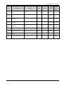
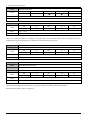
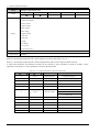
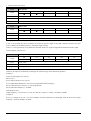
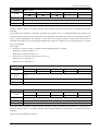
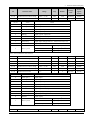
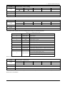
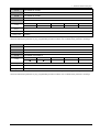
2.3
Menu P03: Start and stop
ID
P03.01
P03.02
Parameter name
Reverse limit control
Deadtime for running
direction change
P03.03
Auto-start after power off
P03.04
Wait time for auto-start
Range
0: reverse is permitted
1: reverse is disable
0.0s~3000.0s
0: off
1: on
0.0s~60.0s
Step
Default
Change
mode
Modbus
register
address
1
0
Stop Only
012CH
0.1s
0.0s
Run&Stop
012DH
1
0
Stop Only
012EH
0.1s
0.0s
Run&Stop
012FH
1
0
Stop Only
0130H
0.01Hz
0.00Hz
Run&Stop
0131H
0: start directly
1: first DC injection, then start
P03.05
Start mode
2: catch spinning
3: reserced
4: reserved
P03.06
Start frequency
0.00Hz~P01.02
P03.07
Hold time for start frequency
0.0s~60.0s
0.1s
0.0s
Run&Stop
0132H
P03.08
Start DC injection current
0.0%~100.0%
0.1%
0.0%
Run&Stop
0133H
P03.09
Start DC injection time
0.0s~60.0s
0.1s
0.0s
Run&Stop
0134H
1
0
Stop Only
0135H
0.01Hz
0.10Hz
Run&Stop
0136H
0: ramp
P03.10
Stop mode
1: coasting
2: ramp+DC injection
3: ramp+coasting
P03.11
Stop frequency
0.00Hz~max. frequency
P03.12
Stop DC injecting frequency
0.0%~20.0%
0.1%
0.0%
Run&Stop
0137H
P03.13
Stop DC injecting current
0.0%~100.0%
0.1%
0.0%
Run&Stop
0138H
P03.14
Stop DC injecting time
0.0s~60.0s
0.1s
0.0s
Run&Stop
0139H
P03.15
Dynamic brake control
1
1
Stop Only
013AH
P03.16
Dynamic brake rate
0.1%
50.0%
Run&Stop
013BH
Stop Only
013CH
P03.17
30
Dynamic brake DC voltage
points
P03.18
Reserved
P03.19
Enable
P03.20
Run bit
P03.21
3-wire enable
0: disable
1: enable
0.0%~100.0%
200V: 390V
200V: 350V~390V
400V: 650V~780V
1V
690V: 1125V
690V: 1000V~1125V
−
0: on
1: off (disable)
0: off
1: on
0: stop
1: run
400V: 780V
−
−
−
−
1
0
Run&Stop
013EH
1
0
Run&Stop
013FH
1
0
Run&Stop
0140H
HD700 Advanced User Manual
2 Parameter detailed description
ID
Parameter name
P03.22
FWD
P03.23
REV
P03.24
FWD/REV
P03.25
Jog forward
P03.26
Jog reverse
P03.27
Comms control word
P03.28
Control word enable
P03.29
Reserved
P03.30
Reverse running indicator
Range
0: off
1: on
0: off
1: on
0: FWD
1: REV
0: off
1: on
0: off
1: on
0~65535
0: disable
1: enable
−
0: forward
1: reverse
Step
Default
Change
mode
Modbus
register
address
1
0
Run&Stop
0141H
1
0
Run&Stop
0142H
1
0
Run&Stop
0143H
1
0
Run&Stop
0144H
1
0
Run&Stop
0145H
1
0
Run&Stop
0146H
1
0
Run&Stop
0147H
−
−
−
−
1
Actual
Actual
0149H
HD700 Advanced User Manual
31
2 Parameter detailed description
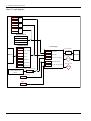
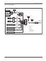
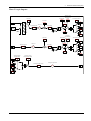
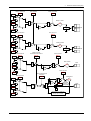
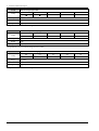
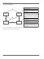
Menu 3 Logic diagram
P10.07 = 2
P10.17 = 0 AND
P03.28 = 1
P10.07 = 1
P10.17 = 1
P10.07 = 0
P10.17 = 0
OR
AND
Keypad control
RUN switch
STOP switch
MF switch
P03.24(FWD/REV)
Terminal control
Menu 9
Control logic
P03.20
Run
P03.21
3-wire enable
P03.05
Start mode
P03.22
Forward
P03.10
Stop mode
P03.23
Reverse
P10.22
Power off stop mode
P03.24
FWD/REV
P03.25
P10.20
Forced DC brake
Jog forward
P10.12
Low DC bus operation
P03.26
Serial communications
control or option card
control
Jog reverse
Jog select indicator Menu 1B
P02.18
Drive is active
P05.27
Comms. Control word
P03.27
Auto-start after power off
P03.03
Enable
P03.19
32
Reverse limit
control
P03.01
HD700 Advanced User Manual
2 Parameter detailed description
P03.01
Reverse limit control
Coding
Range
Default
Change mode
RW
US
PT
■
■
■
ND
PS
ND
PS
0: reverse is permitted
1: reverse is disable
0
Stop Only
The parameter is used to control whether the motor is permitted to run reverse.
P03.02
Deadtime for running direction change
Coding
RW
US
■
■
Range
0.0s~3000.0s
Default
0.0s
Change mode
PT
Run&Stop
The parameter is used to define deadtime for running direction change. Such as t1 shown in the below figure:
Output frequency
Time
t1
Figure 2-3-1
P03.03
Auto-start after power off
Coding
Range
0~1
Default
0
Change mode
Dead time for running direction change
RW
US
■
■
PT
ND
PS
Stop Only
0: auto-start after power off disabled
The drive will not start automatically after power up.
1: auto-start after power off enabled
When power up the drive will start automatically after time defined by P03.04 (wait time for auto-start) if satisfy the start
conditions. When P03.03=1, in different operation command channels, the drive will respond differently after power up.
HD700 Advanced User Manual
33
2 Parameter detailed description
Table 2-3-1
The drive status after restarting in
different operation command channels
Drive status before power off
Drive status after power on
Stop
start
Run command status
Keypad
No run command
Keep stop
Autostart
Serial communications
No run command
Keep stop
Autostart
No run command
Keep stop
Autostart
Run command
Keep stop
Autostart
No run command
Keep stop
Keep stop
Run command
Keep stop
Autostart
Three-wire system 1/2
Two-wire system
NOTE: In order to avoid accidents, please use the function carefully.
P03.04
Wait time for auto-start
Coding
RW
US
■
■
Range
0.0s~60.0s
Default
0.0s
Change mode
PT
ND
PS
Run&Stop
The parameter is used with P03.03 together. Refer to the explanation of parameter P03.03 for detail.
P03.05
Start mode
Coding
Range
0~4
Default
0
Change mode
RW
US
■
■
PT
ND
PS
Stop Only
0: Start directly
Start with the set start frequency (P03.06) and start frequency hold time (P03.07).
1: First brake then start
First DC injection brake (Refer to P03.08、P03.09), then start with mode 0.
2: Catch a spinning motor start
Automatic tracking the motor speed and direction, the running motor can start smoothly without impact.
3: Reserved
4: Reserved
P03.06
Start frequency
Coding
US
■
■
Range
0.00Hz~P01.02
Default
0.00Hz
Change mode
34
RW
PT
Run&Stop
HD700 Advanced User Manual
ND
PS
2 Parameter detailed description
P03.07
Hold time for start frequency
Coding
RW
US
■
■
Range
0.0s~60.0s
Default
0.0s
Change mode
PT
ND
PS
Run&Stop
Start frequency (P03.06) is the initial frequency when the drive starts, as shown in the following picture fs. The start frequency hold
time (P03.07) is the time running at the start frequency when the drive starts, as shown in the following figure t1.
Output frequency
fmax
fs
t1
Figure 2-3-2
P03.08
RW
US
■
■
Range
0.0%~300.0%
Default
0.0%
P03.09
PT
ND
PS
PT
ND
PS
Run&Stop
Start DC injection time
Coding
RW
US
■
■
Range
0.0s~60.0s
Default
0.0s
Change mode
Hold time for start frequency
Start DC injection current
Coding
Change mode
Time
Run&Stop
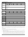
P03.08, P03.09 only effective at first DC injection then start mode (P03.05=1), as shown in the figure 2-3-3.
P03.08 defines the current level used DC injection braking as a percentage of motor rated current. If the Start DC injection brake time
(P03.09) is set to 0.0s, no DC injection when the drive starts.
HD700 Advanced User Manual
35
2 Parameter detailed description
Output frequency
Time
Output voltage
(effective value)
Start DC injection
bake current
(P03.09)
Time
Start DC
injection bake
time (P03.08)
Run command
Figure 2-3-3
P03.10
Stop mode (P00.11)
Coding
Range
0~3
Default
0
Change mode
Start DC injection time
RW
US
PT
■
■
■
ND
PS
Stop Only
0: Ramp stop
When receiving the stop command, the drive ramp down to zero frequency.
1:Coast stop
When receiving the stop command, immediately terminating the output, the drive is freedom to stop as the mechanical
inertia.
2: Ramp stop+DC injection
When receiving the stop command, the drive reduces the output frequency according to deceleration time. When it gets to
the stop DC injection brake start frequency, the DC injection brake begins.
The function about the stop DC injection brake, please refer to the define in P03.08、P03.09.
3: Ramp stop+coast stop
P03.11
Stop frequency
Coding
RW
US
■
■
Range
0.00Hz~maximum frequency
Default
0.10Hz
Change mode
PT
Run&Stop
Set the detection value of stop speed when the drive set to stop.
36
HD700 Advanced User Manual
ND
PS
2 Parameter detailed description
P03.12
Stop DC injecting frequency
Coding
RW
US
■
■
Range
0.0%~100.0%
Default
0.0%
Change mode
PT
ND
PS
Run&Stop
The parameter is used to define DC injection brake initial frequency when set P03.10=2 (coasting).
P03.13
Stop DC injecting current
Coding
RW
US
■
■
Range
0.0%~300.0%
Default
0.0%
Change mode
P03.14
ND
PS
PT
ND
PS
Run&Stop
Stop DC injecting time
Coding
RW
US
■
■
Range
0.00s~60.00s
Default
0.0s
Change mode
PT
Run&Stop
P03.13 defines the current level used DC injection braking as a percentage of motor rated current. If the Start DC
injection brake time (P03.14) is set to 0.0s, no DC injection when the drive starts.
P03.15
Dynamic brake control
Coding
Range
0~1
Default
1
Change mode
RW
US
■
■
PT
ND
PS
PT
ND
PS
Stop Only
0: disable
1: enable
P03.16
Dynamic brake rate
Coding
RW
US
■
■
Range
0.0%~100.0%
Default
50.0%
Change mode
Run&Stop
The value and power of the brake resistor must be considered when set this parameter.
HD700 Advanced User Manual
37
2 Parameter detailed description
P03.17
Dynamic brake DC voltage points
Coding
RW
US
PT
ND
PS
■
■
US
PT
ND
PS
US
PT
ND
PS
200V: 350V~390V
Range
400V: 650V~780V
690V: 1000V~1125V
200V: 390V
Default
400V: 780V
690V: 1125V
Change mode
Stop Only
P03.18
Reserved
RW
Coding
Range
Default
Change mode
P03.19
Enable
P03.20
Run bit
P03.21
3-wire enable
P03.22
FWD
P03.23
REV
P03.24
FWD/REV
P03.25
Jog forward
P03.26
Jog reverse
RW
Coding
■
Range
0~1
Default
0
Change mode
Run&Stop
In the terminal control mode, the motor start and stop is defined by parameters P03.19 to P03.26. The user can set the
parameters control source according to the actual requires. These parameters can be routed to terminals or other control
source.
Read and written results of these parameters are not saved into EEPROM, even if power off. These parameters are reset to
zero after power up.
These parameters (except P03.24) are only enabled in terminal control mode.
If P03.25 or P03.26 is set to 1, then P02.18 is set to 1. It means jog running. If P03.25 is set to 1, jog forward; if
P03.26 is set to 1, jog reverse.
When the drive is not jogging, it tests P03.22 (FWD) and P03.23 (REV) status at first. If one of them is set to 1, the
motor will run as setting. If P03.22 and P03.23 are set to zero, the drive determines whether the motor can run
according to P03.20 status and the direction is defined by P03.24 (FWD/REV). If P03.20 is set to 0, the drive is in
the state of stop. If P03.20 is set to 1, the drive starts. If P03.24 is set to 0, the motor runs forward. If P03.24 is set to
38
HD700 Advanced User Manual
2 Parameter detailed description
1, the motor runs reverse. If P03.22 and P03.23 are set to 1, the motor will stop.
If P03.19 is set to 1, the drive is enabled.
In terminal control mode, terminals control these parameters status. There are two terminal control modes (selected
by P09.22): 2-wire mode and 3-wire mod. P03.21 is 3-wire enable parameter. Refer to the explanation of P09.22.
In keypad control mode, P03.19 to P03.26 (except P03.19 and P03.24) are disabled. P03.24 controls the motor
running forward or reverse.
P03.27
Serial comms control word
RW
Coding
0~65535
Default
0
P03.28
ND
PS
PT
ND
PS
Run&Stop
Serial comms control word enable
Coding
Range
0~1
Default
0
Change mode
PT
■
Range
Change mode
US
RW
US
■
■
Run&Stop
P03.27 and P03.28 used Serial comms control word provide one of start and stop modes. When P03.28 is disable
(P03.28=0), control word is ineffective. Driver start/stop operation is not used P03.27.
P03.27 is a 16-bit binary number. The meanings of each bit are shown as the following table. It is displayed in decimal
form on the keypad.
Table 2-3-2
Serial comms control word
Bit
Bit function
As same parameter
0
Drive enable
P03.19
1
Run
P03.20
2
3-wire enable
P03.21
3
Run forward
P03.22
4
Run reverse
P03.23
5
FOR/REV
P03.24
6
Jog forward
P03.25
7
Jog reverse
P03.26
8
Reset trips
P12.15
9
Save parameters
−
10
clean trip recoding
−
11
Enable comms to write parameters
−
12
Reserved
−
13
Reserved
−
14
Reserved
−
15
Reserved
−
Bit 0~7: Start and stop logic control of the drive. In serial communication control mode (P01.03=1), the user can control
HD700 Advanced User Manual
39
2 Parameter detailed description
the drive by changing comms control word (P03.12).
Bit 8: The bit changing from 0 to 1 will reset the drive (fault conditions disappear and the failure code < F030).
Bit 9: The bit changing from 0 to 1 will bring parameters saved to the EEPROM.
Bit 10: The bit changing from 0 to 1 will clean error recording of the drive.
Bit 11: The bit changing from 0 to 1 will make selector parameters become effective.
Bit 0~7: Start and stop logic control of the drive. They have the same function with P03.19 to P03.27 but they are not
affected by P03.19 to P03.27. Changing the value of P03.27 each bit will not cause P03.19 to P03.26 to change and vice
versa. In serial communication control mode (P00.03 or P10.07=2), the user can control the drive by changing comms
control word (P03.27).
Table 2-3-3
Source reference is serial communication
Source parameter selector
Analogue output function selector
P08.13
Relay function selector
P09.10, P09.11
Digital output function selector
P09.30, P09.31
PID reference source
P15.01, P15.02, P15.03
Logic block source
P16.01, P16.03, P16.08, P16.10
Threshold block source and variable selector
P17.01, P17.06, P17.11, P17.12, P17.18,
source
P17.19, P17.25, P17.26
Function selector of E-pot output
P02.28
Analogue input function selector
P08.03, P08.08
Digital input terminal function selector
P09.02 to P09.08
PID output function selector
P15.15
Logic block output function selector
P16.07, P16.14, P16.19
Threshold block and variable output function
selector
P17.05, P17.10, P17.17, P17.24, P17.31
NOTE:
These parameters are set through the keypad, it will be effective after pressing the PRG key;
Different destination parameter selector select the same destination parameter will cause function conflict, to avoid
the conflict:
When the parameter is set through the keypad, the function will not be effective after pressing the PRG key,
and not enter into the next function code;
When the parameter is set through serial communication or HDSoft (PCTools), the drive will produce trip
F021.
The commonly used settings of P03.27 are shown as below (only list low 8 bits). These can be used directly if required.
P03.27=1 (00000001)
enable
P03.27=8 (00001000) or P03.27=2 (00000010)
run forward
P03.27=16 (00010000) or P03.27=34 (00100010)
run reverse
P03.27=64 (01000000)
jog forward
P03.27=128 (10000000)
jog reverse
For serial communications refer to chapter 4 MODBUS communication.
40
HD700 Advanced User Manual
2 Parameter detailed description
P03.29
Reserved
RW
US
PT
ND
PS
US
PT
ND
PS
■
■
■
Coding
Range
Default
Change mode
P03.30
Reverse running indicator
RW
Coding
Range
Change mode
0~1
Actual
The parameter is used to indicate if the driver is running reverse or not
0: Running forward
1: Running reverse
HD700 Advanced User Manual
41
2 Parameter detailed description
2.4
Menu P04: Preset and PLC
ID
Parameter name
Range
Step
Default
Change
mode
Modbus
register
address
P04.01
Preset1
0.01Hz
5.00Hz
Run&Stop
0190H
P04.02
Preset 2
0.01Hz
10.00Hz
Run&Stop
0191H
P04.03
Preset 3
0.01Hz
20.00Hz
Run&Stop
0192H
P04.04
Preset 4
0.01Hz
30.00Hz
Run&Stop
0193H
P04.05
Preset 5
0.01Hz
40.00Hz
Run&Stop
0194H
P04.06
Preset 6
0.01Hz
45.00Hz
Run&Stop
0195H
P04.07
Preset 7
0.01Hz
50.00Hz
Run&Stop
0196H
P04.08
Preset 8
0.01Hz
5.00Hz
Run&Stop
0197H
0.01Hz
10.00Hz
Run&Stop
0198H
Min. frequency~Max. frequency
P04.09
Preset 9
P04.10
Preset 10
0.01Hz
20.00Hz
Run&Stop
0199H
P04.11
Preset 11
0.01Hz
30.00Hz
Run&Stop
019AH
P04.12
Preset 12
0.01Hz
40.00Hz
Run&Stop
019BH
P04.13
Preset 13
0.01Hz
45.00Hz
Run&Stop
019CH
P04.14
Preset 14
0.01Hz
50.00Hz
Run&Stop
019DH
P04.15
Preset 15
0.01Hz
50.00Hz
Run&Stop
019EH
P04.16
Preset 16
0.01Hz
50.00Hz
Run&Stop
019FH
1
0
Stop Only
01A0H
1
1
Stop Only
01A1H
1
0
Stop Only
01A2H
0.1s
0.0
Run&Stop
01A3H
1
0
Run&Stop
01A4H
0.1s
0.0
Run&Stop
01A5H
1
0
Run&Stop
01A6H
0: disabled
P04.17
PLC mode
1: single cycle then stop
2: single cycle and keep the last speed
3: recycle
P04.18
PLC power off saving mode
0: power off without saving
1: power off with saving
0: from first step speed
1: from the step speed which is the one
P04.19
PLC restart mode
at last stop (trip)
2: from the speed which is the one at
last stop (trip)
P04.20
PLC step1 running time
0.0s~6553.5s
0: Accel./Decel. Rate 1
P04.21
PLC Step1 Accel./ Decel.
1: Accel./Decel. Rate 2
Rate selector
2: Accel./Decel. Rate 3
3: Accel./Decel. Rate 4
P04.22
PLC step2 running time
0.0s~6553.5s
0: Accel./Decel. Rate 1
P04.23
PLC Step2 Accel./ Decel.
1: Accel./Decel. Rate 2
Rate selector
2: Accel./Decel. Rate 3
3: Accel./Decel. Rate 4
42
HD700 Advanced User Manual
2 Parameter detailed description
ID
P04.24
Parameter name
PLC step3 running time
Range
0.0s~6553.5s
Step
Default
Change
mode
Modbus
register
address
0.1s
0.0
Run&Stop
01A7H
1
0
Run&Stop
01A8H
0.1s
0.0
Run&Stop
01A9H
1
0
Run&Stop
01AAH
0.1s
0.0
Run&Stop
01ABH
1
0
Run&Stop
01ACH
0.1s
0.0
Run&Stop
01ADH
1
0
Run&Stop
01AEH
0.1s
0.0
Run&Stop
01AFH
1
0
Run&Stop
01B0H
0.1s
0.0
Run&Stop
01B1H
1
0
Run&Stop
01B2H
0.1s
0.0
Run&Stop
01B3H
1
0
Run&Stop
01B4H
0.1s
0.0
Run&Stop
01B5H
1
0
Run&Stop
01B6H
0: Accel./Decel. Rate 1
P04.25
PLC Step3 Accel./ Decel.
1: Accel./Decel. Rate 2
Rate selector
2: Accel./Decel. Rate 3
3: Accel./Decel. Rate 4
P04.26
PLC step4 running time
0.0s~6553.5s
0: Accel./Decel. Rate 1
P04.27
PLC Step4 Accel./ Decel.
1: Accel./Decel. Rate 2
Rate selector
2: Accel./Decel. Rate 3
3: Accel./Decel. Rate 4
P04.28
PLC step5 running time
0.0s~6553.5s
0: Accel./Decel. Rate 1
P04.29
PLC Step5 Accel./ Decel.
1: Accel./Decel. Rate 2
Rate selector
2: Accel./Decel. Rate 3
3: Accel./Decel. Rate 4
P04.30
PLC step6 running time
0.0s~6553.5s
0: Accel./Decel. Rate 1
P04.31
PLC Step6 Accel./ Decel.
1: Accel./Decel. Rate 2
Rate selector
2: Accel./Decel. Rate 3
3: Accel./Decel. Rate 4
P04.32
PLC step7 running time
0.0s~6553.5s
0: Accel./Decel. Rate 1
P04.33
PLC Step7 Accel./ Decel.
1: Accel./Decel. Rate 2
Rate selector
2: Accel./Decel. Rate 3
3: Accel./Decel. Rate 4
P04.34
PLC step8 running time
0.0s~6553.5s
0: Accel./Decel. Rate 1
P04.35
PLC Step8 Accel./ Decel.
1: Accel./Decel. Rate 2
Rate selector
2: Accel./Decel. Rate 3
3: Accel./Decel. Rate 4
P04.36
PLC step9 running time
0.0s~6553.5s
0: Accel./Decel. Rate 1
P04.37
PLC Step9 Accel./ Decel.
1: Accel./Decel. Rate 2
Rate selector
2: Accel./Decel. Rate 3
3: Accel./Decel. Rate 4
P04.38
PLC step10 running time
0.0s~6553.5s
0: Accel./Decel. Rate 1
P04.39
PLC Step10 Accel./ Decel.
1: Accel./Decel. Rate 2
Rate selector
2: Accel./Decel. Rate 3
3: Accel./Decel. Rate 4
HD700 Advanced User Manual
43
2 Parameter detailed description
ID
P04.40
Parameter name
PLC step11 running time
Range
0.0s~6553.5s
Step
Default
Change
mode
Modbus
register
address
0.1s
0.0
Run&Stop
01B7H
1
0
Run&Stop
01B8H
0.1s
0.0
Run&Stop
01B9H
1
0
Run&Stop
01BAH
0.1s
0.0
Run&Stop
01BBH
1
0
Run&Stop
01BCH
0.1s
0.0
Run&Stop
01BDH
1
0
Run&Stop
01BEH
0.1s
0.0
Run&Stop
01BFH
1
0
Run&Stop
01C0H
0.1s
0.0
Run&Stop
01C1H
1
0
Run&Stop
01C2H
1
0
Run&Stop
01C3H
1
Actual
Actual
01C4H
1
Actual
Actual
01C5H
0: Accel./Decel. Rate 1
P04.41
PLC Step11 Accel./ Decel.
1: Accel./Decel. Rate 2
Rate selector
2: Accel./Decel. Rate 3
3: Accel./Decel. Rate 4
P04.42
PLC step12 running time
0.0s~6553.5s
0: Accel./Decel. Rate 1
P04.43
PLC Step12 Accel./ Decel.
1: Accel./Decel. Rate 2
Rate selector
2: Accel./Decel. Rate 3
3: Accel./Decel. Rate 4
P04.44
PLC step13 running time
0.0s~6553.5s
0: Accel./Decel. Rate 1
P04.45
PLC Step13 Accel./ Decel.
1: Accel./Decel. Rate 2
Rate selector
2: Accel./Decel. Rate 3
3: Accel./Decel. Rate 4
P04.46
PLC step14 running time
0.0~6553.5
0: Accel./Decel. Rate 1
P04.47
PLC Step14 Accel./ Decel.
1: Accel./Decel. Rate 2
Rate selector
2: Accel./Decel. Rate 3
3: Accel./Decel. Rate 4
P04.48
PLC step15 running time
0.0s~6553.5s
0: Accel./Decel. Rate 1
P04.49
PLC Step15 Accel./ Decel.
1: Accel./Decel. Rate 2
Rate selector
2: Accel./Decel. Rate 3
3: Accel./Decel. Rate 4
P04.50
PLC step16 running time
0.0s~6553.5s
0: Accel./Decel. Rate 1
P04.51
PLC Step16 Accel./ Decel.
1: Accel./Decel. Rate 2
Rate selector
2: Accel./Decel. Rate 3
3: Accel./Decel. Rate 4
P04.52
PLC running time unit
P04.53
PLC finished indicator
P04.54
PLC recycle mode indicator
44
0: second
1: hour
0: not finished
1: finished
0: no-recycle
1: recycle
HD700 Advanced User Manual
2 Parameter detailed description
Simple PLC running function and MS (multi section) speed running are used for realizing the drive's variable speed
running according to certain regulations. For MS (multi section) speed running, the switching of multi-frequency and the
change of running direction is realized through external control terminals and different combination of FWD and REV.
For Simple PLC running function, not only one circulating Multi-frequency can be defined in function codes, but also the
Multi-frequency running time, direction and circulation times can also be defined in function codes.
One cycle of PLC running diagram is shown in Figure 2-4-1.
Setup frequency of f1~f16 is defined in function code P04.01~P04.16.
a1 to a16 is acceleration process for each phase and d1 to d16 is deceleration process for each phase. T1 to T16 is
each phase's running time. Please refer to the explanation of parameters P04.20 to P04.51.
When one cycle of PLC running finishes, it can be indicated by digital output terminals or relay output signal. Refer to
the explanation of P04.53.
f15
f2
a15
a2
d16
f14
f1
f16
d3
a14
a1
User programmed
PLC running
a3
f3
d14
a4
f4
T1
T2
T3
T4
T5~T13
T14
T15
T16
Simple PLC
finished indicator
Figure 2-4-1
Simple PLC running
HD700 Advanced User Manual
45
2 Parameter detailed description
P04.01
Preset1
P04.02
Preset2
P04.03
Preset3
P04.04
Preset4
P04.05
Preset5
P04.06
Preset6
P04.07
Preset7
P04.08
Preset8
P04.09
Preset9
P04.10
Preset10
P04.11
Preset11
P04.12
Preset12
P04.13
Preset13
P04.14
Preset14
P04.15
Preset15
P04.16
Preset16
Coding
RW
US
■
■
Range
Min. frequency~Max. frequency
Default
Refer to Menu P04 table
Change mode
PT
ND
Run&Stop
P01.01 (P00.04) =5 (serial communication), setup frequency is defined by parameter P04.01.
46
HD700 Advanced User Manual
PS
2 Parameter detailed description
P04.17
PLC mode
RW
US
■
■
Coding
Range
0~3
Default
0
Change mode
PT
ND
PS
Run&Stop
Set P04.17=0, disable PLC function.
Set P04.17=1, stop after single PLC cycle as below.
As the figure, VFD will stop after a PLC cycle. Restart needs one more RUN command.
f
f15
f2
a15
a2
d16
f14
f1
f16
d3
a14
a1
a3
User programmed
t
f3
d14
a4
f4
T1
T2
T3
T4
T5~T13
T14
T15
T16
Running
command
Running status
(P05.27)
Simple PLC
finished signal
Figure 2-4-2
Stop after a PLC cycle PLC
Set P04.17=2, stay at the last reference after one cycle.
As the figure, VFD will keep the frequency and direction after a PLC cycle.
f
f15
f2
a15
a2
d16
f14
f1
f16
d3
a14
a1
a3
t
f3
d14
a4
f4
T1
T2
T3
T4
T5~T13
T14
T15
T16
Running command
PLC finish indicator
(P04.53)
Figure 2-4-3
Stay at the last reference after one PLC cycle
HD700 Advanced User Manual
47
2 Parameter detailed description
Set P04.17=3, continue the cycles.
As the figure, VFD always starts a new cycle after cycles until a STOP command.
f
f15
f2
f15
f16
f1
f14
f16
f2
f1
f3
f14
f3
f4
f1
f14
t
f3
f4
f5~f13
The first cycle
f2
f4
f5~f13
The second cycle
f5~f13
Running
command
Figure 2-4-4
P04.18
PLC power off saving mode
Coding
Range
Default
Change mode
PLC continuous cycle
RW
US
■
■
PT
ND
PS
0: power off without saving
1: power off with saving
1
Run&Stop
0: power off without saving
VFD does not store the PLC state when power off and restart from preset1 after RUN command valid when power on
again.
1: power off with saving
VFD stores the PLC state including running frequency, etc. when power off.
48
HD700 Advanced User Manual
2 Parameter detailed description
P04.19
PLC restart mode
Coding
RW
US
■
■
PT
ND
PS
0: from first step speed
Range
1: from the step speed which is the one at last stop (trip)
2: from the speed which is the one at last stop (trip)
Default
0
Change mode
Run&Stop
Set P04.19=0, restart from first step speed
f
f2
f2
f1
f14
f1
f3
f14
t
f3
f4
f4
f5~f13
f5~f13
Running
command
Figure 2-4-5
Restart from first step speed
Set P04.19=1, restart from the step speed which is the one at last stop (trip)
f
f2
a2
d3
f1
a1
a3
t
f3
a4
f4
T1
T2
T3
a1: phase 1 acceleration process
f1: phase 1 frequency
T1: phase 1 running time
a2: phase 2 acceleration process
f2: phase 2 frequency
T2: phase 2 running time
a3: phase 3 acceleration process
f3: phase 3 frequency
T3: phase 3 running time
a4: phase 4 acceleration process
f4: phase 4 frequency
T4: phase 4 running time
T4
Running
command
Interrupt
Figure 2-4-6
Restart from the step speed that is the one at last stop (trip)
HD700 Advanced User Manual
49
2 Parameter detailed description
Set P04.19=2, restart from the speed which is the one at last stop (trip)
f
f2
a2
d3
f1
a1
a3
d3
a3
f3
a4
f4
T1
T2
T3
a1: phase 1 acceleration process
f1: phase 1 frequency
T1: phase 1 running time
a2: phase 2 acceleration process
f2: phase 2 frequency
T2: phase 2 running time
a3: phase 3 acceleration process
t f3: phase 3 frequency
T3: phase 3 running time
a4: phase 4 acceleration process
f4: phase 4 frequency
T4: phase 4 running time
T4
Running
command
interrupt
Figure 2-4-7
Restart from the speed that is the one at last stop (trip)
NOTE:
The difference between mode1 & mode2 is that mode2 stores the frequency when power off, and VFD restarts from this
frequency, while mode1 not.
50
PLC running is limited by start frequency (P03.06).
HD700 Advanced User Manual
2 Parameter detailed description
P04.20
PLC step1 running time
P04.22
PLC step2 running time
P04.24
PLC step3 running time
P04.26
PLC step4 running time
P04.28
PLC step5 running time
P04.30
PLC step6 running time
P04.32
PLC step7 running time
P04.34
PLC step8 running time
P04.36
PLC step9 running time
P04.38
PLC step10 running time
P04.40
PLC step11 running time
P04.42
PLC step12 running time
P04.44
PLC step13 running time
P04.46
PLC step14 running time
P04.48
PLC step15 running time
P04.50
PLC step16 running time
Coding
RW
US
■
■
Range
0.0s~6553.5s
Default
0.0s
Change mode
PT
ND
PS
Run&Stop
The parameters above set the time for PLC preset running stably.
NOTE: Set “0.0”, means that the corresponding preset is invalid.
HD700 Advanced User Manual
51
2 Parameter detailed description
P04.21
PLC step1 acceleration/deceleration rate selector
P04.23
PLC step2 acceleration/deceleration rate selector
P04.25
PLC step4 acceleration/deceleration rate selector
P04.27
PLC step5 acceleration/deceleration rate selector
P04.29
PLC step6 acceleration/deceleration rate selector
P04.31
PLC step7 acceleration/deceleration rate selector
P04.33
PLC step8 acceleration/deceleration rate selector
P04.35
PLC step9 acceleration/deceleration rate selector
P04.37
PLC step10 acceleration/deceleration rate selector
P04.39
PLC step11 acceleration/deceleration rate selector
P04.41
PLC step12 acceleration/deceleration rate selector
P04.43
PLC step13 acceleration/deceleration rate selector
P04.45
PLC step14 acceleration/deceleration rate selector
P04.47
PLC step15 acceleration/deceleration rate selector
P04.49
PLC step16 acceleration/deceleration rate selector
P04.51
PLC step17 acceleration/deceleration rate selector
Coding
RW
US
■
■
PT
ND
PS
PT
ND
PS
0: acceleration/deceleration rate 1
Range
1: acceleration/deceleration rate 2
2: acceleration/deceleration rate 3
3: acceleration/deceleration rate 4
Default
Change mode
0
Run&Stop
0: corresponds to P02.04 and P02.05;
1: corresponds to P02.06 and P02.07;
2: corresponds to P02.08 and P02.09;
3: corresponds to P02.10 and P02.11;
P04.52
PLC running time unit
Coding
Range
Default
Change mode
RW
US
■
■
0: s
1: H
0
Run&Stop
When P04.52=0, Each phase's running time is recorded by second.
When P04.52=1, Each phase's running time is recorded by hour.
52
HD700 Advanced User Manual
2 Parameter detailed description
P04.53
PLC finished indicator
P04.54
PLC recycle mode indicator
RW
US
Coding
Range
Change mode
PT
ND
PS
■
0~1
Actual
When simple PLC running is finished, P04.53=1.
When simple PLC is cycle running, P04.54=1.
HD700 Advanced User Manual
53
2 Parameter detailed description
2.5
ID
P05.01
P05.02
Menu P05: Keypad and display
Parameter name
Normal keypad display
select
Keypad cycle display
mode
Range
P01.01~P18.08
Step
Default
Change
mode
Modbus
register
address
0.01
P05.11
Run&Stop
01F4H
1
0
Run&Stop
01F45H
1
0
Run&Stop
01F6H
1
0
Stop Only
01F7H
1
0
Run&Stop
01F8H
1
0
Run&Stop
01F9H
1
0
Run&Stop
01FAH
0~2
0: only menu P00
P05.03
Parameter display
1: all menus parameters
range control
2: only parameters which setup is
different with default
0: no action
P05.04
Parameter cloning
1: cloning up to Keypad
2: cloning down to the drive
0: Chinese
P05.05
LCD language
1: English
2: reserved
0: unlock
P05.06
Keypad Lock control
1: all keys are locked
2: except RUN&STOP, all other keys
are locked
0: Jog
P05.07
MF key function select
1: FWD/REV
2: Coasting Stop
3: reserved
P05.08
Motor speed
−18000rpm~+18000rpm
1rpm
Actual
Actual
01FBH
P05.09
Factor for load speed
0.1%~1000.0%
0.1%
100.0%
Run&Stop
01FCH
P05.10
Mechanical load speed
−180000rpm~+180000rpm
1rpm
Actual
Actual
01FDH
P05.11
Output frequency
−max. frequency~+max. frequency
0.01Hz
Actual
Actual
01FEH
P05.12
Output voltage
0V~drive rated voltage
1V
Actual
Actual
01FFH
1V
Actual
Actual
0200H
0.1A
Actual
Actual
0201H
0.1A
Actual
Actual
0202H
0.1A
Actual
Actual
0203H
0.1%
Actual
Actual
0204H
200V: 230V~415V
P05.13
DC voltage
400V: 250V~830V
690V: 400V~1190V
P05.14
Output current
P05.15
Torque current
P05.16
Magnetizing current
P05.17
Output power
54
0.0A~3×Motor rated current
−3×motor rated current~3×motor
rated current
0.0A~3×Motor rated current
0.0%~300.0%
(refer to motor rated power)
HD700 Advanced User Manual
2
ID
P05.18
P05.19
Parameter name
Running time log: year.
day
Running time log:
hour. minute
Range
Step
Parameter detailed description
Default
Change
mode
Modbus
register
address
0.000~9.364 year. day
0.001year.date
Actual
Actual
0205H
0.00~23.59hour.minute
0.01hour.minute
Actual
Actual
0206H
P05.20
Energy meter: MWh
0.0MWh~999.9MWh
0.1MWh
Actual
Actual
0207H
P05.21
Energy meter: kWh
0.00kWh~99.99kWh
0.01kWh
Actual
Actual
0208H
P05.22
Electric price/kWh
0.0~0.99 (currency/kWh)
0.00
Run&Stop
0209H
P05.23
Energy meter reset
0
Run&Stop
020AH
P05.24
Average running cost
0~10000 (currency/hour)
Actual
Actual
020BH
P05.25
Heatsink temperature
−25℃~127℃
1℃
Actual
Actual
020CH
−25℃~200℃
1℃
Actual
Actual
020DH
1
Actual
Actual
020EH
1
Actual
Actual
020FH
0.00~99.99
0.01
−
Actual
0210H
0.00~99.99
0.01
−
Actual
0211H
0.00~99.99
0.01
−
Actual
0212H
0.00~99.99
0.01
−
Actual
0213H
P05.26
P05.27
IGBT junction
temperature
Drive is active
0.01
(currency/kWh)
0: no action
1
1: reset
1
(currency/hour)
0: drive is at ready or trip stage
1: drive is running
0: output current is less than motor
P05.28
Rated load is on
rated current
1: output current equals motor rated
current
P05.29
P05.30
P05.31
P05.32
Control MCU software
version
Power MCU software
version
LCD software version
Brigde rectifier
software version
HD700 Advanced User Manual
55
2 Parameter detailed description
P05.01
Normal keypad display select
Coding
RW
US
PT
■
■
■
Range
P01.01~P18.08
Default
P05.11
Change mode
ND
PS
ND
PS
Run&Stop
P05.01 defines the content of Keypad (display mode).
P05.02
Keypad cycle display mode
Coding
Range
0~2
Default
0
Change mode
RW
US
■
■
PT
Run&Stop
0: Normal dispaly is the value of the parameter which is selected by the P05.01; default is output frequency (value of
P05.11).
HD700 has a quick display group, switchover value is: output frequency, reference frequency, output current, output
voltage, DC bus voltage. Operation procedure is as figure 2-5-1:
Output frequency Reference frequency Output current
0.00
0.00
Figure 2-5-1
Output voltage
0
0.0
DC bus voltage
537
Display switchover flow
1: On standby mode, normal display is reference frequency. Operation procedure is as figure 2-5-2:
Reference frequency Output frequency
0.00
Output current
0.00
Figure 2-5-2
Output voltage
0.0
0
DC bus voltage
537
Display switchover flow
On running mode, normal display is output frequency. Operation procedure is as figure 2-5-3:
Output frequency Reference frequency Output current
0.00
0.00
Figure 2-5-3
Output voltage
0
0.0
DC bus voltage
537
Display switchover flow
2: Reserved
P05.03
Parameter display range control (P00.02)
Coding
RW
US
PT
■
■
■
0: only menu P00
Range
1: all menus parameters
2: only parameters which setup is different with default
Default
Change mode
56
0
Run&Stop
HD700 Advanced User Manual
ND
PS
2 Parameter detailed description
P05.04
Parameter cloning
RW
US
PT
■
■
■
Coding
ND
PS
0: no action
Range
1: cloning up to Keypad
2: cloning down to the drive
Default
Change mode
0
Stop Only
0: no action
1: cloning up to Keypad
If the parameter is set to 1, the drive automatically performs the value of P01.01 to P18.08 save to its internal EEPROM.
2: cloning down to the drive
If the parameter is set to 2, the values of P01.01 to P18.08 that are cloned up to keypad are automatically loaded to the
drive.
NOTE:
P05.04 is set back to 0 after cloning parameters.
Only the parameters with US attribution can be cloned.
Before cloning down to the drive from Keypad, cloning up to Keypad from the drive is necessary. After cloning up
to Keypad from the drive, the parameters are stored in EEPROM on Keypad forever.
Before cloning down to the drive from Keypad, the drive checks the version and integrality of parameters from
Keypad at first, and then trips if some errors occur such as parameters being empty, or some parameter lacked, or
version different.
Cloning down to drive from Keypad can be operated many times for the parameter existed in EEPROM on Keypad.
P05.05
LCD language
Coding
RW
US
■
■
PT
ND
PS
0: Chinese
Range
1: English
2: Reserved
Default
Change mode
0
Run&Stop
The parameter is used to select the language of LCE keypad displaying.
NOTE: This function is effective only for LCD keypad.
HD700 Advanced User Manual
57
2 Parameter detailed description
P05.06
Keypad lock control
Coding
RW
US
■
■
PT
ND
PS
0: unlock
Range
1: all keys are locked
2: except RUN&STOP, all other keys are locked
Default
Change mode
0
Run&Stop
The parameter is used to select if the keys are locked or not.
Keypad lock function enable: set P05.06 > 0, press PRG key and then the keys are locked.
Keys unlocked operation: press the ESC key more than 5 seconds, the value of P05.06 to be automatic recovery is 0, and
the keyboard is unlocked. When unlock the keys, parameter P05.07 will flash once on the keypad.
P05.07
MF key function select
Coding
RW
US
■
■
PT
ND
PS
PT
ND
PS
■
■
0: Jog
Range
1: FWD/REV
2: Coasting Stop
3: Reserved
Default
Change mode
0
Run&Stop
The parameter is used to define the specific function of MF key.
P05.08
Motor speed
RW
US
Coding
Range
Change mode
−18000rpm~+18000rpm
Actual
The parameter is used to display the actual motor speed.
NOTE: There is a 5-digit LED display on the HD700 Drive standard keypad. When motor speed is less than or equal to
−10000rpm, the highest decimal point means a minus.
For example:
18000rpm is shown as 18000
−8000rpm is shown as −8000
−18000rpm is shown as 1.8000
58
HD700 Advanced User Manual
2 Parameter detailed description
P05.09
Factor for load speed
Coding
RW
US
■
■
Range
0.1%~1000.0%
Default
100.0%
Change mode
PT
ND
PS
Run&Stop
Set load speed ratio (transmission ratio) according to different load transmission ratio. Setting the correct load speed ratio
can load properly load speed.
P05.10
Mechanical load speed
RW
US
Coding
Range
Change mode
PT
ND
■
■
PS
−180000rpm~+180000rpm
Actual
The actual load speed: P05.10=P05.09×P05.08
NOTE: There is a 5-digit LED display on the HD700 Drive standard keypad. When load speed is less than or equal to
−10000rpm, the highest decimal point represents a minus. When load speed is less than −100000rpm, the decimal point
indicates a minus and the lowest order hided. When load speed more than 100000rpm, the decimal point indicates the
lowest order hided.
For example:
18123rpm is shown as 18123
175426rpm is shown as 1754.2
−8123rpm is shown as −8123
−18123rpm is shown as 1.8123
−175426rpm is shown as 17.542
The parameter cannot be read and written in serial communications mode.
P05.11
Output frequency
RW
US
Coding
Range
Change mode
P05.12
■
■
PT
ND
■
■
PS
Actual
Output voltage
RW
Change mode
ND
−max. frequency~+max. frequency
Coding
Range
PT
US
PS
0V~drive rated voltage
Actual
The parameter is used to define the effective value of fundamental voltage.
HD700 Advanced User Manual
59
2 Parameter detailed description
P05.13
DC voltage
RW
US
PT
ND
■
■
PT
ND
■
■
PT
ND
■
■
PT
ND
■
■
PT
ND
■
■
Coding
PS
200V: 230~415V
Range
400V: 250~830V
690V: 400~1190V
Change mode
Actual
The parameter is used to define the value of drive DC busbar voltage.
P05.14
Output current
RW
US
Coding
Range
Change mode
PS
0.0A~3× motor rated current
Actual
The parameter is used to define drive output current.
P05.15
Torque current
RW
US
Coding
Range
Change mode
P05.16
−3×motor rated current~3×motor rated current
Actual
Magnetizing current
RW
US
Coding
Range
Change mode
P05.17
Actual
Output power
RW
Change mode
PS
0.0A~3×motor rated current
US
Coding
Range
PS
PS
0.0%~300.0% (refer to motor rated power)
Actual
The parameter is used to monitor drive output power refer to the percentage of motor rated power.
P05.18
Running time log: year. date
RW
Coding
Range
Change mode
US
PT
ND
PS
■
■
■
0.000~9.364 year. date
Actual
The parameter is used to record the drive running time log after the drive delivery.
60
HD700 Advanced User Manual
2 Parameter detailed description
P05.19
Running time log: hour. minute
RW
US
Coding
Range
Change mode
P05.20
P05.21
■
■
US
PT
ND
PS
■
■
■
PT
ND
PS
■
■
■
0.0 MWh~999.9MWh
Actual
Energy meter: kWh
RW
Change mode
■
Energy meter: MWh
US
Coding
Range
PS
Actual
RW
Change mode
ND
0.00~23.59 hour. minute
Coding
Range
PT
0.00kWh~99.99kWh
Actual
Energy meter indicates the energy value of drive supplied (unit: kWh, MWh). P05.20 and P05.21 indicate the
accumulated value of drive output frequency.
When P05.23=1, the energy meter is reset to be 0.
P05.22
Electric price/kWh
Coding
RW
US
■
■
Range
0.0~0.99 (currency/kWh)
Default
0.00
Change mode
P05.23
ND
PS
PT
ND
PS
PT
ND
PS
■
■
Run&Stop
Energy meter reset
RW
Coding
US
■
Range
0~1
Default
0
Change mode
PT
Run&Stop
When P05.23=1, the energy meter is reset to be 0.
P05.24
Average running cost
RW
Coding
Range
Change mode
US
−0~10000 (currency/hour)
Actual
If set P05.22 correctly, the parameter indicates drive every hour running cost.
HD700 Advanced User Manual
61
2 Parameter detailed description
P05.25
Heatsink temperature
RW
US
Coding
Range
Change mode
P05.26
PT
ND
■
■
PT
ND
−25℃~127℃
Actual
IGBT junction temperature
RW
US
Coding
Range
Change mode
PS
PS
■
−25℃~200℃
Actual
The IGBT junction temperature is calculated using heatsink temperature (P05.25) and a thermal model of the drive power
stage. The resulting temperature is displayed in this parameter. The calculated IGBT junction temperature is used to
modify the drive switching frequency to reduce losses if the devices become too hot.
P05.27
Drive is active
P05.28
Rated load is on
RW
US
Coding
Range
Change mode
■
■
PT
ND
■
■
PS
Actual
Control MCU software version
P05.30
Power MCU software version
P05.31
LCD software version
P05.32
Brigde rectifier software version
RW
Coding
Change mode
ND
0~1
P05.29
Range
PT
US
PS
0.00~99.99
Actual
The drive software version consists of two numbers xx.yy that are displayed in these parameters. Where xx specifies a
change that affects hardware compatibility, yy specifies a change that affects product documentation.
Plug the LED keyboard in, P05.31 displays 0.
62
HD700 Advanced User Manual
2 Parameter detailed description
2.6
Menu P06: V/F controls parameters
Modbus
ID
Parameter name
Range
Step
Default
Change mode
register
address
0: user programmed V/F ramp
P06.01
V/F control mode
1: 2 law ramp
2: 1.7 law ramp
1
0
Stop Only
0258H
3: 1.2 law ramp
P06.02
V/F frequency 3
(P06.04)~(P13.08)
0.01Hz
0.00Hz
Stop Only
0259H
P06.03
V/F voltage3
(P06.05)~100.0%
0.1%
0.0%
Stop Only
025AH
P06.04
V/F frequency 2
(P06.06)~(P06.02)
0.01Hz
0.00Hz
Stop Only
025BH
P06.05
V/F voltage 2
(P06.07)~(P06.03)
0.1%
0.0%
Stop Only
025CH
P06.06
V/F frequency 1
0.00~(P06.04)
0.01Hz
0.00Hz
Stop Only
025DH
P06.07
V/F voltage 1
0~(P06.05)
0.1%
0.0%
Stop Only
025EH
P06.08
Voltage boost
0.0%~30.0%
0.1%
By model
Run&Stop
025FH
P06.09
Boost finish frequency
0.0%~50.0%
0.1%
50.0%
Run&Stop
0260H
P06.10
Stable factor control
1
0
Run&Stop
0261H
P06.11
Auto energy saving control
1
0
Stop Only
0262H
1
1
Stop Only
0263H
0: off
1: on
0: off
1: on
0: off
P06.12
AVR control
1: on for all condition
2: on except ramp
NOTE: (Pxx.xx) means the value of Pxx.xx.
HD700 Advanced User Manual
63
2 Parameter detailed description
P06.01
V/F control mode (P00.23)
Coding
RW
US
PT
■
■
■
ND
PS
0:user programmed V/F ramp
Range
1: 2 law ramp
2: 1.7 law ramp
3: 1.2 law ramp
Default
Change mode
0
Stop Only
Different V/F characteristic is defined by P06.01 (P00.23) to meet the demanding from different load.
There are three kinds of fixed curve and one user programmed line
When P06.01 (P00.23) is 1, it is a 2.0 law ramp, curve1 in figure 2-6-1.
When P06.01 (P00.23) is 2, it is a 1.7 law ramp, curve2 in figure 2-6-1.
When P06.01 (P00.23) is 3, it is a 1.2 law ramp, curve3 in figure 2-6-1.
Output voltage
Motor rated voltage
0
3
2
1
Motor rated frequency
Figure 2-6-1
P06.02
V/F frequency 3
P06.04
V/F frequency 2
P06.06
V/F frequency 1
Coding
US
■
■
Motor V/F curve
PT
ND
Range
P06.04≤P06.02≤P13.08, P06.06≤P06.04≤P06.02, 0.00≤P06.06≤P06.04
Default
0.00Hz
Change mode
64
RW
Output frequency
Stop Only
HD700 Advanced User Manual
PS
2 Parameter detailed description
P06.03
V/F voltage 3
P06.05
V/F voltage 2
P06.07
V/F voltage 1
Coding
RW
US
■
■
PT
ND
Range
P06.05≤P06.03≤100.0%, P06.07≤P06.05≤P06.03, 0≤P06.07≤P06.05
Default
0.0%
Change mode
PS
Stop Only
When P06.01 is set to 0, the user can set up the parameters P06.02~P06.07 to define the V/F curve, by add three points
(V1, f1), (V2, f2), (V3, f3) on the V/F curve showed as below, this can improve the performance during the acceleration
under specific application situation, under default set up, the V/F is a straight line.
Voltage (%)
100
V3
V2
V1
f1
f2
f3
fb
Frequency (Hz)
fb: motor rated frequency
Figure 2-6-2
P06.08
Coding
V/F curve defined by user
Voltage boost (P00.22)
RW
US
PT
■
■
■
Range
0.0%~30.0%
Default
By model
Change mode
Run&Stop
ND
PS
The parameter is used to compensate the low frequency voltage. In order to compensate V/F control low frequency
voltage boost characteristic, compensate the drive output voltage. If the voltage boost is set too great, the motor is easy to
overheat and the drive will produce overcurrent. Adjusting the parameter correctly will protect the drive from overcurrent
when the drive starts. It is better to increase the parameter setting value for heavy load, otherwise decrease the parameter
setting value. When P06..08 is set to 0.0%, the voltage boost is disabled.
The parameter is used with P06.09 (boost finish frequency) together. When P06.09=0, the voltage boost is disabled. When
P06.09≠0, the voltage boost is active if the output frequency is less than the boost finish frequency; the voltage boost is
disabled if the output frequency exceeds the boost finish frequency. The default of P06.09 is 50% (refer to motor rated
frequency).
The default of P06.08 is dependent on the drive power as given in the table below:
Table 2-6-1
the default value of voltage boost
Drive power
Default
0.4kW~4kW
3.0%
5.5kW~15kW
2.0%
18.5kW~37kW
1.0%
HD700 Advanced User Manual
65
2 Parameter detailed description
P06.09
Drive power
Default
45kW~75kW
0.5%
90kW above
0.0%
Boost finish frequency
RW
US
■
■
Coding
Range
0.0%~50.0%
Default
50.0%
Change mode
PT
ND
PS
Run&Stop
Refer to the explanation of P06.08.
Output voltage
Ve
Ve: motor rated voltage
Vb: boost voltage=Ve×P06.08 (P00.22)
fZ: boost close frequency (P06.09)
Vb
fb: motor rated frequency
fz
Figure 2-6-3
P06.10
Default
Change mode
P06.11
Default
Change mode
66
RW
US
■
■
PT
ND
PS
PT
ND
PS
0: off
1: on
0
Run&Stop
Auto energy saving control
Coding
Range
Voltage boost
Stable factor control
Coding
Range
fb Output frequency
RW
US
■
■
0: off
1: on
0
Run&Stop
HD700 Advanced User Manual
2 Parameter detailed description
P06.12
AVR control
Coding
RW
US
PT
■
■
■
ND
PS
0: off
Range
1: on for all condition
2: on except ramp
Default
Change mode
1
Run&Stop
AVR is auto voltage regulation. When the drive's input voltage differs with the rated input voltage, the drive's output
voltage can be stabilized by adjusting the width of PWM wave.
This function is usually enabled, especially when the input voltage is higher than the rated input voltage.
HD700 Advanced User Manual
67
2 Parameter detailed description
2.7
Menu P07: Vector
ID
P07.01
Parameter name
Range
Speed/Torque mode change
0: only stop
condition
1: Run&stop
0: speed
Step
Default
Change
mode
Modbus
register
address
1
0
Run&Stop
02BCH
1
0
Run&Stop
02BDH
0.1%
200.0%
Run&Stop
02BEH
−
−
−
−
P07.02
Speed/Torque control selector
P07.03
Current limit
0.0%~300.0%
P07.04
~
P07.11
Reserved
−
P07.12
Current controller Kp gain
0.001~10.000
0.001
0.020
Run&Stop
02C7H
P07.13
Current controller Ki gain
0.00s~100.00s
0.01s
0.20s
Run&Stop
02C8H
1
0
Stop Only
02C9H
1: torque
0: Enable current limit protection
1: Disable current limit protection
P07.14
Current limit protection
above fundamental frequency
2: Current limit protection disabled
at fast increase or decrease
3: Both disabled
P07.15
Slip compensation error
0rpm~1500rpm
1rpm
0rpm
Run&Stop
02CAH
P07.16
Active current limit
0.0%~300.0%
0.1%
200.0%
Run&Stop
02CBH
P07.17
Regen. Current limit
0.0%~300.0%
0.1%
150.0%
Run&Stop
02CCH
0.01Hz
50.00Hz
Run&Stop
02CDH
1
1
Stop Only
02CEH
P07.18
Maximum speed under torque
mode
0.00Hz~1.2×P01.02
0: Keypad
1: AI1
2: AI2
P07.19
Torque mode reference source
3: Pulse (DI7)
4: Serial communications
5: User programmed
6: option module
68
P07.20
Torque gain
0.0%~300.0%
0.1%
100.0%
Run&Stop
02CFH
P07.21
Torque offset
0.0%~100.0%
0.1%
0.0%
Run&Stop
02D0H
P07.22
Torque reference display
-300.0%~+300.0%
0.1%
Actual
Actual
02D1H
P07.23
Reserved
−
−
−
−
−
P07.24
Torque being limited indicator
1
Actual
Actual
02D3H
0: not limited
1: being limited
HD700 Advanced User Manual
2 Parameter detailed description
Menu 7A Logic diagram
Power up keypad reference
P01.11
0.00Hz
Running reference
when last time
power off
Keypad reference display
0
1
2
P01.09
Preset 1
P04.01
Torque mode reference source
Analogue input 1
AI1
AI2
M
E
N
U
8
P08.17
Torque offset
Analogue input 2
P08.18
DI7 level of input frequency
DI7 pulse reference
P07.19
P09.38
0
1
2
3
4
5
6
Preset 1
Communication setting torque
P07.21
Torque gain
P07.20
Torque reference
display
P07.22
Torque reference
0: Keypad
1: AI1
2: AI2
3: Pulse (DI7)
4: Serial comms.
5: User programmed
6: Optional module
P04.01
User PID
Options
HD700 Advanced User Manual
69
2 Parameter detailed description
Menu 7B Logic diagram
Speed/torque control
AC
Motor
P07.02
Setup reference display
P01.14
Acceleration/dec
eleration rate
Menu 2A
0
1
P07.12
Current controller Kp gain
P07.13
Current controller Ki gain
Motor
control
Menu 13
Torque being
limited indicator
Menu 7A
Torque can
be converted
to current
P07.24
P07.03
Current limit
P07.16
Active current limit
P07.17
Regenerate current limit
P13.07 Motor 1 rated current
P13.19 Motor 2 rated current
70
HD700 Advanced User Manual
Torque current
P05.15
Torque current
Output current
P05.14
P05.16
Magnetizing
current
Motor protection
Menu 7C
2 Parameter detailed description
Menu 7C Logic diagram
P03.15
Dynamic brake control
P03.17
Dynamic brake DC
voltage points
P07.03
Current limit
P07.16
Active current limit
P07.17
Regenerate current limit
P13.07
Motor 1 rated current
P13.19
Motor 2 rated current
P12.02
Ramp hold by high
voltage threshold
Output phase loss
Software undervoltage point set
P12.11
P12.10
P21.05
P12.12
P12.03 High voltage threshold
Motor overload
protection mode
Overload factor
Menu 7B
Motor protection
P05.25
P05.26
P05.28
Heatsink
temperature
IGBT
junction
temperature
100% load
P07.24
P12.14
P12.16
P12.17
Torque being
Overload
Under voltage
limited External fault
accumulation
indicator
indicator
indicator
HD700 Advanced User Manual
71
2 Parameter detailed description
P07.01
Speed/torque mode change condition
Coding
Range
0~1
Default
0
Change mode
RW
US
■
■
PT
ND
PS
Run&Stop
The parameter is used to control whether changing the value of P07.02 (speed/torque control mode) is allowed when the
drive is running.
0: P07.02 cannot be changed during running
1: P07.02 can be changed during running
P07.02
Speed/torque control selector
Coding
Range
0~1
Default
0
Change mode
RW
US
■
■
PT
ND
PS
Run&Stop
0: speed control mode
The drive operates speed control. In speed control mode, the drive outputs frequency according to the setting frequency
and output torque is automatically matched with load torque. However, output torque is limited by the upper limit of
output torque (P07.03, P07.16, P07.17). When load torque is greater than the upper limit of output torque, output
frequency and reference frequency are not the same.
1: torque control mode
The drive operates torque control. The drive outputs torque (current) according to torque command and output frequency
is automatically matched with load. However, output frequency is limited by P07.18 (maximum speed under torque
mode). When load speed is greater than the upper limit of frequency, the drive output frequency is limited and output
torque is different with reference torque.
In torque control mode, select torque reference source by P07.19 (torque mode reference source). The final torque
reference is affected by torque gain and torque offset. The relation between them as shown below:
Torque reference=(the value of torque mode reference source +torque offset)×torque gain
Load torque < setup torque: the output frequency rises, when it arrives at the high limit, the drive will be running at the
high limit frequency.
Load torque > setup torque: the output frequency decreases, when it arrives at the low limit, the drive will be running at
the low limit frequency.
P07.03
Current limit
Coding
RW
US
■
■
Range
0.0%~300.0%
Default
200.0%
Change mode
PT
ND
PS
Run&Stop
Current limit is effective to electric/power generation torque limit. When P07.03=100%, it corresponds to motor rated
current.
72
HD700 Advanced User Manual
2 Parameter detailed description
P07.04
Reserved
P07.05
Reserved
P07.06
Reserved
P07.07
Reserved
P07.08
Reserved
P07.09
Reserved
P07.10
Reserved
P07.11
Reserved
RW
US
PT
ND
PS
RW
US
PT
ND
PS
■
■
PT
ND
PS
Coding
Range
Default
Change mode
P07.12
Current controller Kp gain
Coding
Range
0.001~10.000
Default
0.020
Change mode
P07.13
Run&Stop
Current controller Ki gain
Coding
RW
US
■
■
Range
0.00s~100.00s
Default
0.20s
Change mode
Run&Stop
These parameters control the proportional and integral gains of the current controller. Increasing proportional gains or
reducing integral gains can make the controller respond quickly. Proportional gains too high or integral gains too long
will make the controller instable.
Adjustment method:
If the default setting is not suitable for some applications, the user can adjust the performance of the controller: ensure the
controller is stable, increase proportional gains first, and then reduce integral gains to make the controller respond quickly.
The controller has smaller overshoot.
HD700 Advanced User Manual
73
2 Parameter detailed description
P07.14
Current limit protection
Coding
RW
US
■
■
PT
ND
PS
0: Enable current limit protection
Range
1: Disable current limit protection above fundamental frequency
2: Current limit protection disabled at fast increase or decrease
3: Both disabled
Default
Change mode
0: Enable current limit protection
Stop Only
0: Enable current limit protection
1: Disable current limit protection above fundamental frequency
In general, when the motor is running above fundamental frequency, the current limit factor will decrease automatically
according to the output frequency to keep constant power.
If P07.14=1, then current limit factor will not be changed.
2: Current limit protection disabled at fast increase or decrease
At fast increase or decrease, the drive will not alarm over current fault (F001) in a short time. In this condition, the drive
will predict the value of current that can possibly arrive. If the predicting current value is larger, the drive will
automatically adjust the acceleration or deceleration rate. This function is valid when the acceleration or deceleration rate
is less than one second. If P07.14=2, the drive will not automatically adjust the acceleration or deceleration rate.
3: Both disabled
Note: P07.14 = 1, the current limit protection is disabled above fundamental frequency, the motor may be damaged.
Please use this function carefully.
P07.15
Slip compensation error
Coding
RW
US
■
■
Range
0rpm~1500rpm
Default
0
Change mode
PT
ND
PS
Run&Stop
Changing motor load torque will affect motor running slip and cause motor speed changing. When motor speed is
different with the setting motor speed, the user can adjust slip compensation to realize the actual motor speed is the same
with the setting motor speed.
P07.16
Active current limit
Coding
RW
US
■
■
Range
0.0%~300.0%
Default
200.0%
Change mode
PT
ND
Run&Stop
Active current limit, when the parameter is set to 100%, it corresponds to the drive rated torque.
74
HD700 Advanced User Manual
PS
2 Parameter detailed description
P07.17
Regen. current limit
RW
US
■
■
Coding
Range
0.0%~300.0%
Default
150.0%
Change mode
PT
ND
PS
Run&Stop
Regeneration current limit, when the parameter is set to 100%, it corresponds to the drive rated torque.
P07.18
Maximum speed under torque mode
RW
US
■
■
Coding
Range
0.00~1.2×P01.02
Default
50.00Hz
Change mode
PT
ND
PS
ND
PS
Run&Stop
The parameter is used to limit the upper threshold of motor speed in torque mode.
P07.19
Torque mode reference source
Coding
RW
US
PT
■
■
■
0: Keypad
1: AI1
2: AI2
Range
3: Pulse (DI7)
4: Serial communications
5: User programmed
6: option module
Default
Change mode
1
Stop Only
0: keypad
Change the frequency reference through adjusting ▲ or ▼ switches, and the Power up value is decided by parameter
P01.11 (P00.12).
1: AI1
In this mode, adjust torque reference by changing analogue input 1.
About AI1 signal mode, there are current mode and voltage mode.
When AI1 is selected as torque reference source, if P08.01=0 (analogue input basic application function), must set
P08.03=0 (AI1 is analogue input frequency reference);
When P08.01=1 (analogue input advanced application function), muse set P08.03=P01.02 (AI2 is analogue input
frequency reference).
2: AI2
In this mode, adjust torque reference by changing analogue input 2.
AI2 has only voltage mode.
When AI2 is selected as reference source for torque reference, if P08.01=1 (analogue input basic application), must set
P08.08=0 (analogue input 2). If P08.01=1 (analogue input advanced application), must set P08.08=P01.21 (analogue
HD700 Advanced User Manual
75
2 Parameter detailed description
input 2).
About AI1 and AI2, refer to Menu P08 for details.
3: DI7 pulse input
In this mode,
4: serial communications
In this mode, the user can adjust torque reference by changing the value of P04.01 (preset1).
5: PID
In this mode, the user can adjust torque reference by changing PID output (P15.22).
6: option module
P07.20
Torque gain
Coding
RW
US
■
■
Range
0.0%~300.0%
Default
100.0%
Change mode
PT
ND
PS
PT
ND
PS
Run&Stop
This parameter is used to scale the torque input if so desired.
P07.21
Torque offset
Coding
RW
US
■
■
Range
0.0%~100.0%
Default
0.0%
Change mode
Run&Stop
An offset can be added to torque input with a range from -100% to 100%. If the sum of the input and the offset exceeds
±200%, the result is limited to ±200%.
76
HD700 Advanced User Manual
2 Parameter detailed description
P07.22
Torque reference display
RW
US
PT
ND
Coding
PS
■
−300.0%~+300.0%
Range
Change mode
Actual
Power up keypad reference
P01.11
0
Keypad reference display
Running
referency
when last
power off
0
1
2
P01.09
Preset1 (P04.01)
AI1
M
E
N
U
8
AI2
AI1
Torque mode
reference source
P08.17
P07.19
Torque offset
AI2
P08.18
DI7 level of input frequency
Pulse (DI7)
Serial communication
P09.38
Torque gain
P07.20
Torque reference
display
P07.22
Torque mode reference:
0: Keypad
1: AI1
2: AI2
3: Pulse (DI7)
4: Serial comms.
5: User programmed
P04.01
PID output
User programmed
P07.21
0
1
2
3
4
5
6
P15.22
6: option module
Option module
Figure 2-7-1
torque mode diagram
HD700 Advanced User Manual
77
2 Parameter detailed description
P07.23
Reserved
RW
US
PT
ND
PS
PT
ND
PS
Coding
Range
Default
Change mode
P07.24
Torque being limited indicator
RW
Coding
Range
Change mode
US
■
0: not limited
1: being limited
Actual
The parameter indicates whether torque is limited. It means the current limit is enabled.
78
HD700 Advanced User Manual
2 Parameter detailed description
2.8
ID
Menu P08: Analogue input and output
Parameter name
Range
Step
Default
Change
mode
Modbus
register
address
0: P08.03 and P08.08 are only basic applications
P08.01
Analogue input
(0~3)
function level control
1: P08.03 and P08.08 are advanced applications
1
0
Run&Stop
0320H
1
6
Stop Only
0321H
1
0
Stop Only
0322H
(P00.00~P18.08)
0: 0mA~20mA
1: 20mA~0mA
2: 4mA~20mA (current loosing with trip)
P08.02
AI1 mode
3: 20mA~4mA (current loosing with trip)
4: 4mA~20mA (current loosing without trip)
5: 20mA~4mA (current loosing without trip)
6: 0V~10V
0: analogue input1
1: speed limit (Torque control)
P08.03
AI1 function select
2: Torque offset
3: No function
99: Advanced function
P08.04
AI1 offset
−100.0%~+100.0%
0.1%
0.0%
Run&Stop
0323H
P08.05
AI1 scaling
0.000~20.000
0.001
1.000
Run&Stop
0324H
P08.06
AI1 inverter
1
0
Run&Stop
0325H
P08.07
AI1 filtering time
0.01s
0.1s
Run&Stop
0326H
1
0
Stop Only
0327H
0: off
1: on
0.00s~10.00s
0: analogue input2
1: speed limit (Torque control)
P08.08
AI2 function select
2: Torque offset
3: No function
99: Advanced function
P08.09
AI2 offset
−100.0%~+100.0%
0.1%
0.0%
Run&Stop
0328H
P08.10
AI2 scaling
0.000~20.000
0.001
1.000
Run&Stop
0329H
P08.11
AI2 inverter
1
0
Run&Stop
032AH
P08.12
AI2 filtering time
0.01s
0.1s
Run&Stop
032BH
1
0
Run&Stop
032CH
P08.13
Analogue output
function level control
0: off
1: on
0.00s~10.00s
0: P08.14 is only basic application (0~11)
1: P08.14 is advanced application
(P00.00~P18.08)
HD700 Advanced User Manual
79
2 Parameter detailed description
ID
Parameter name
Range
Step
Default
Change
mode
Modbus
register
address
0: output frequency
1: reference frequency
2: active current
3: output current
4: motor speed
P08.14
Analogue output
function select
5: DC voltage
6: output voltage
1
0
Run&Stop
032DH
0.001
1.000
Run&Stop
032EH
Actual
032FH
7: AI1 level
8: AI2 level
9: length
10: counting
11: No function
99: Advanced function
P08.15
Analogue output
scaling
0.000~20.000
Current loosing
0: no loosing
indicator
1: loosing
P08.17
AI1 level
0.0%~100.0%
0.1%
Actual
Actual
0330H
P08.18
AI2 level
0.0%~100.0%
0.1%
Actual
Actual
0331H
P08.19
Analogue output level
0.0%~100.0%
0.1%
Actual
Actual
0332H
P08.20
AI1 upper limit
0.0%~100.0%
0.1%
100.0%
Run&Stop
0333H
P08.21
AI1 lower limit
0.0%~P08.20
0.1%
0.0%
Run&Stop
0334H
P08.22
AI2 upper limit
0.0%~100.0%
0.1%
100.0%
Run&Stop
0335H
P08.23
AI2 lower limit
0.0%~P08.22
0.1%
0.0%
Run&Stop
0336H
P08.16
1
Actual
NOTE: For parameters P08.03, P08.08, P08.14, when the advanced function returns to basic function, if there is no
corresponding options, will display “99”, and the advanced fuction will continue to take effect.
80
HD700 Advanced User Manual
2 Parameter detailed description
Menu 8 Logic diagram
Analogue input
function level
AI1 inverter
control
AI1 mode
P08.02
0
1
2
3
4
5
6
Current
loop loss
188R
AI1 offset
P08.04
AI1 function select
P08.03
0
AI1 upper limit
P08.20
AI1 filtering time AI1 level
P08.07
P08.01
P08.06
AI1 scaling
0
1
P08.05
P08.17
3
0
1
P00.00
x(-1)
P08.21
AI1 lower limit
P18.08
Analogue
input function
AI2 inverter level control
AI2 offset
P08.11
P08.09
P08.01
P08.08
0
AI2 upper
limit
AI2 filtering time
P08.12
AI2 level
P08.22
AI2 scaling
P08.10
P08.18
AI2 function select
0
1
0
1
3
P00.00
x(-1)
P08.23
AI2 lower limit
0
11
P00.00
Analogue output
function select
Analogue output
function level control
P08.14
P08.13
0
1
Analogue output scaling
P08.15
P18.08
Analogue output level
P08.19
P18.08
HD700 Advanced User Manual
81
2 Parameter detailed description
P08.01
Analogue input function level control
Coding
Range
Default
Change mode
RW
US
PT
■
■
■
ND
PS
0: P08.03 and P08.08 are only basic applications (0~3)
1: P08.03 and P08.08 are advanced applications (P00.00~18.08)
0
Run&Stop
HD700 analogue input terminals have basic and advanced applications function. The parameter is used to select the
analogue input terminals are basic applications or advanced applications.
P08.01=0, analogue input terminals are basic applications, P08.03 and P08.08 value range is 0 to 3.
P08.01=1, analogue input terminals are advanced applications, P08.03 and P08.08 value range is P00.00 to P18.08. Refer
to the explanation of P08.03 and P08.08.
P08.02
AI1 mode (P00.05)
Coding
RW
US
PT
■
■
■
ND
PS
0: 0mA~20mA
1: 20mA~0mA
2: 4mA~20mA (current loosing with trip)
Range
3: 20mA~4mA (current loosing with trip)
4: 4mA~20mA (current loosing without trip)
5: 20mA~4mA (current loosing without trip)
6: 0V~10V
Default
Change mode
6
Stop Only
AI1 is a voltage/current reference input.
0: 0mA~20mA
1: 20mA~0mA
2: 4mA~20mA (current loosing with trip)
3: 20mA~4mA (current loosing with trip)
4: 4mA~20mA (current loosing without trip)
5: 20mA~4mA (current loosing without trip)
6: 0V~10V
In modes 0 to 5, if the current input is over 26mA, the drive will initiate a F012 trip and stop as the mode defined by the
setting of P03.10, and then turn off the IGBTs.
In modes 2 or 3, if the current input falls below 3mA, the drive will initiate a F013 trip and stop as the mode defined by
the setting of P03.10, and then turn off IGBTs.
NOTE: If in modes 2 to 5, once the current input falls below 3mA, P08.16 (current loosing indicator) is 1.
82
HD700 Advanced User Manual
2 Parameter detailed description
P08.03
AI1 function select
Coding
RW
US
PT
■
■
■
ND
PS
0: analogue input1
1: speed limit (Torque control)
Range
2: Torque offset
3: No function
99: Advanced function
Default
Change mode
0
Stop Only
The parameter is analogue input 1 function selector.
When P08.01=0, analogue input terminals are basic applications function. There are three applications:
P08.03=0, AI1 is analogue input1 reference. When AI1 scaling (P08.05) and AI1 inverter (P08.06) are set to default,
input range that is defined by AI1 reference (P01.20) is converted to 0.0% to 100.0%.
P08.03=1, AI1 is speed limit in torque control mode. When AI1 scaling (P08.05) and AI1 inverter (P08.06) are set to
default, input range corresponds to speed limit in torque control mode (P07.18) of 0.0% to 100.0%. 100.0%
corresponds to 1.2 times of maximum frequency (P01.02).
When P08.03=2, AI1 is torque offset. When AI1 scaling (P08.05) and AI1 inverter (P08.06) are set to default, input
range corresponds to torque offset (P07.21) of 0.0% to 100.0%.
When P08.01=1, P08.03 value range is P01.01 to P18.08. It means that P08.03 can select any effective parameters to AI1
(parameters attribute allows and no conflict).
By default, when the value of P08.01 is changed to 1 from 0, P08.03 changes to P08.03=P01.20 from P08.03=0. It means
P01.20 is analogue input 1 reference frequency.
P08.04
AI1 offset
Coding
RW
US
■
■
Range
−100.0%~+100.0%
Default
0.0%
Change mode
PT
ND
PS
Run&Stop
An offset can be added to each analogue input with a range from -100% to 100%. If the sum of the input and the offset
exceeds ±100%, the result is limited to ±100%.
The parameter defines AI1 offset.
P08.05
AI1 scaling
Coding
RW
US
■
■
Range
0.000~20.000
Default
1.000
Change mode
PT
ND
PS
Run&Stop
This parameter is used to scale the analogue input 1 if so desired.
HD700 Advanced User Manual
83
2 Parameter detailed description
P08.06
AI1 inverter
Coding
Range
0~1
Default
0
Change mode
RW
US
■
■
PT
ND
PS
Run&Stop
This parameter can be used to invert the analogue input1 reference (i.e. multiply the input scaling result by -1).
P08.07
AI1 filtering time
Coding
RW
US
■
■
Range
0.00s~10.00s
Default
0.10s
Change mode
PT
ND
PS
ND
PS
ND
PS
Run&Stop
The parameter can be used to adjust AI1 filtering time.
P08.08
AI2 function select
Coding
RW
US
PT
■
■
■
RW
US
PT
■
■
0: analogue input2
1: speed limit (Torque control)
Range
2: Torque offset
3: No function
99: Advanced function
Default
Change mode
0
Stop Only
Refer to the explanation of P08.03.
P08.09
AI2 offset
Coding
Range
−100.0%~+100.0%
Default
0.0%
Change mode
Run&Stop
An offset can be added to each analogue input with a range from -100% to 100%. If the sum of the input and the offset
exceeds ±100%, the result is limited to ±100%.
The parameter defines AI2 offset.
84
HD700 Advanced User Manual
2 Parameter detailed description
P08.10
AI2 scaling
Coding
RW
US
■
■
Range
0.000~20.000
Default
1.000
Change mode
PT
ND
PS
PT
ND
PS
Run&Stop
This parameter is used to scale the analogue input 2 if so desired.
P08.11
AI2 inverter
Coding
Range
Default
Change mode
RW
US
■
■
0: off
1: on
0
Run&Stop
This parameter can be used to invert the analogue input 2 reference (i.e. multiply the input scaling result by -1).
P08.12
AI2 filtering time
Coding
RW
US
■
■
Range
0.00s~10.00s
Default
0.10s
Change mode
PT
ND
PS
PT
ND
PS
Run&Stop
The parameter can be used to adjust AI2 filtering time.
P08.13
Analogue output function level control
Coding
Range
Default
Change mode
RW
US
■
■
0: P08.14 is only basic application (0~11)
1: P08.14 is advanced application (P00.00~P18.08)
0
Run&Stop
HD700 analogue output terminals have basic and advanced applications function. The parameter is used to select the
analogue output terminals are basic applications or advanced applications.
P08.13=0, the analogue output terminal is basic applications. P08.14 value range is 0 to 11. Refer to the explanation of
P08.14.
P08.13=1, the analogue output terminal is advanced applications, P08.14 value range is P00.00 to P18.08.
HD700 Advanced User Manual
85
2 Parameter detailed description
P08.14
Analogue output function select
Coding
RW
US
■
■
PT
ND
PS
0: output frequency
1: reference frequency
2: active current
3: output current
4: motor speed
5: DC voltage
Range
6: output voltage
7: AI1 level
8: AI2 level
9: length
10: counting
11: No function
99: Advanced function
Default
Change mode
0
Run&Stop
The parameter is used to select analogue output function.
P08.13=0, the analogue output terminal is basic applications. P08.14 value range is 0 to 11.
P08.13=1, the analogue output terminal is advanced applications, P08.14 value range is P00.00 to P18.08.
It means that parameters from P00.00 to P18.08 can be selected as source parameter by P08.14. Actually, a basic
application corresponds to a source parameter as shown in the table below:
Table 2-8-1
Corresponding parameter of analogue output function
P08.13=0, P08.14= P08.13=1, P08.14=
Function
Corresponding output at 100% AI1
0
P05.11
Output frequency
Maximum frequency
1
P01.14
Reference frequency
Maximum frequency
2
P05.15
Torque current
Three times of the motor rated current
3
P05.14
Output current
Three times of the motor rated current
4
P05.08
Motor speed
Motor speed (rpm)
220: 415V
5
P05.13
DC bus voltage
400: 830V
690: 1125V
86
6
P05.12
Output voltage
Motor rated voltage
7
P08.17
AI1
10V
8
P08.18
AI2
10V
9
P14.11
Actual length
60000
10
P14.15
Set number
60000
11
—
No function
—
HD700 Advanced User Manual
2 Parameter detailed description
P08.15
Analogue output scaling
Coding
RW
US
■
■
Range
0.000~20.000
Default
1.000
Change mode
P08.16
PS
PT
ND
PS
■
■
Current loosing indicator
RW
Change mode
ND
Run&Stop
US
Coding
Range
PT
0: no loosing
1: loosing
Actual
If P08.02 (P00.05) is set to 2 to 5, once the current input falls below 3mA, P08.16 (current loosing indicator) is set to 1.
P08.17
AI1 level
RW
US
Coding
Range
Change mode
PT
ND
■
■
PS
0.0%~100.0%
Actual
This parameter displays the level of the analogue signal present at analogue input 1.
In voltage mode, this is a unipolar voltage input where the input range is 0 to +10V.
In current mode, this is a unipolar current input having a maximum measurable input of 20mA. The drive can be
programmed to convert the measured current to any one of the defined ranges in P08.02. The selected range is converted
to 0 to 100.0%.
P08.18
AI2 level
RW
US
Coding
Range
Change mode
PT
ND
■
■
PS
0.0%~100.0%
Actual
This parameter displays the level of the analogue signal present at analogue input 2.
This is a unipolar voltage input having a range of 0 to +10V that is converted to 0 to 100%.
P08.19
Analogue output level
RW
US
Coding
Range
Change mode
PT
ND
■
■
PS
0.0%~100.0%
Actual
This parameter displays the level of the analogue output by percentage form.
For example:
When analogue output voltage is 5V, P08.19=
5V×100%
=50.0%
10V
HD700 Advanced User Manual
87
2 Parameter detailed description
P08.20
AI1 upper limit
Coding
RW
US
■
■
Range
0.0%~100.0%
Default
0
Change mode
PT
ND
PS
Run&Stop
The parameter is used to set the upper limit of AI1. If the actual analogue input is greater than the upper limit, then it is
equal to the upper limit value.
P08.21
AI1 lower limit
Coding
RW
US
■
■
Range
0.0%~P08.20
Default
0
Change mode
PT
ND
PS
Run&Stop
The parameter is used to set the lower limit of AI1. If the actual analogue input is less than the lower limit, then it is equal
to the lower limit value.
P08.22
AI2 upper limit
Coding
RW
US
■
■
Range
0.0%~100.0%
Default
0
Change mode
PT
ND
PS
Run&Stop
The parameter is used to set the upper limit of AI2. If the actual analogue input is greater than the upper limit, then it is
equal to the upper limit value.
P08.23
AI2 lower limit
Coding
RW
US
■
■
Range
0.0%~P08.20
Default
0
Change mode
PT
ND
PS
Run&Stop
The parameter is used to set the lower limit of AI2. If the actual analogue input is less than the lower limit, then it is equal
to the lower limit value.
88
HD700 Advanced User Manual
2 Parameter detailed description
2.9
ID
Menu P09: Digital input and output
Parameter name
Range
Step
Default
Change
mode
Modbus
register
address
0: P09.02 to P09.08 are basic applications
P09.01
Digital input function level
control
(0~16)
1: P09.02 to P09.08 are advanced
1
0
Run&Stop
0384H
applications
(P00.00~P18.08)
P09.02
DI1 function
0: preset select bit 0
DI1: 3
0385H
DI2: 4
0386H
DI3: 7
0387H
1: preset select bit 1
2: run
P09.03
DI2 function
3: run forward (FWD)
4: run reverse (REV)
5: 3-wire enable
P09.04
DI3 function
6: FWD/REV
7: Jog forward
P09.05
DI4 function
8: UP
9: DOWN
1
DI4: 0
Stop Only
0388H
10: enable
P09.06
DI5 function
11: reset
DI5: 1
0389H
DI6: 10
038AH
DI7: 11
038BH
12: control channel is switched to terminal
13: reset length counting
P09.07
DI6 function
14: reset number counting
15: external trip
16: no function
P09.08
DI7 function
99: advanced function
0: P09.10~P09.11 are basic applications
P09.09
Status relays function level
(0~12)
control
1: P09.10~P09.11 are advanced
1
0
Run&Stop
038CH
applications (P00.00~P18.08)
HD700 Advanced User Manual
89
2 Parameter detailed description
ID
Parameter name
Range
Step
Default
Change
mode
Modbus
register
address
0: drive healthy
1: drive active
2: length arrival
P09.10
Relay1 function
Relay1: 0
3: external trip
Run&Stop
038DH
4: under voltage trip
5: PLC finished
6:frequency reached
7: torque limit is working
1
8: time arrival
9: overload is calculating
P09.11
Relay2 function
10: at zero speed
Relay2: 1
038EH
11: brake logic is on
12: no function
99: advanced function
P09.12
DI1 inverter
P09.13
DI2 inverter
P09.14
DI3 inverter
P09.15
DI4 inverter
P09.16
DI5 inverter
P09.17
DI6 inverter
P09.18
DI7 inverter
P09.19
Relay1 inverter
P09.20
Relay2 inverter
P09.21
DI common select
0: off
1: on
0: off
1: on
0: off
1: on
0: off
1: on
0: off
1: on
0: off
1: on
0: off
1: on
0: off
1: on
0: off
1: on
0: 0V
1: 24V
1
0
Run&Stop
038FH
1
0
Run&Stop
0390H
1
0
Run&Stop
0391H
1
0
Run&Stop
0392H
1
0
Run&Stop
0393H
1
0
Run&Stop
0394H
1
0
Run&Stop
0395H
1
0
Run&Stop
0396H
1
0
Run&Stop
0397H
1
0
Stop Only
0398H
1
0
Stop Only
0399H
1
0
Run&Stop
039AH
0: disable
P09.22
3-wire mode
1: 3-wire 1
2: 3-wire 2
0: normal digit
P09.23
DI6 mode
1: length counting pulse
2: number counting pulse
90
HD700 Advanced User Manual
2 Parameter detailed description
ID
Parameter name
Range
Step
Default
Change
mode
Modbus
register
address
0: normal digit
P09.24
DI7 mode
1: motor thermistor
1
0
Run&Stop
039BH
2: high frequency pulse
P09.25
Reserved
−
−
−
−
−
P09.26
Reserved
−
−
−
−
−
0.1kHz
10.0kHz
Run&Stop
039EH
1
0
Run&Stop
039FH
1
0
Run&Stop
03A0H
P09.27
DI7 maximum frequency of
input pulse
0.1kHz~50.0kHz
0: no center
P09.28
DI7 center of frequency of
input pulse
1: center = P09.27/2, frequency less than
center is negative
2: center = P09.27/2, frequency less than
center is positive
0: P09.30~P09.31 are basic applications
P09.29
Digital output function level (0~8)
control
1: P09.30~P09.31 are advanced
applications (P00.00~P18.08)
0: PLC is running recycle
1: drive is active
P09.30
DO1 function
2: drive is alarming
DO1: 6
03A1H
3: 100% current
4: drive healthy
5: length counting arrival
1
Run&Stop
6: running at zero speed
P09.31
DO2 function
7: brake logic is on
DO2: 2
03A2H
8: no function
99: advanced function
P09.32
DO1 inverter
P09.33
DO2 inverter
P09.34
DO2 maximum frequency
of output pulse
0: off
1: on
0: off
1: on
0.1kHz~50.0kHz
1
0
Run&Stop
03A3H
1
0
Run&Stop
03A4H
0.1kHz
10.0kHz
Run&Stop
03A5H
1
0
Run&Stop
03A6H
0: Digital signal output
P09.35
DO2 output mode selection
1: Pulse output
2: PWM output
P09.36
Reserved
−
−
−
−
−
P09.37
Reserved
−
−
−
−
−
P09.38
DI7 level of input frequency −100.0%~+100.0%
0.1%
Actual
Actual
03A9H
P09.39
Reserved
−
−
−
−
−
HD700 Advanced User Manual
91
2 Parameter detailed description
ID
Parameter name
P09.40
DI1 status
P09.41
DI2 status
P09.42
DI3 status
P09.43
DI4 status
P09.44
DI5 status
P09.45
DI6 status
P09.46
DI7 status
P09.47
Relay1 status
P09.48
Relay2 status
P09.49
DO1 status
P09.50
DO2 status
Range
0: off
1: on
0: off
1: on
0: off
1: on
0: off
1: on
0: off
1: on
0: off (P09.23≠0)
1: on
0: off (P09.24≠0)
1: on
0: off
1: on
0: off
1: on
0: output 0V
1: output 24V
0: output 0V
1: output 24V
Step
Default
Change
mode
Modbus
register
address
1
Actual
Actual
03ABH
1
Actual
Actual
03ACH
1
Actual
Actual
03ADH
1
Actual
Actual
03AEH
1
Actual
Actual
03AFH
1
Actual
Actual
03B0H
1
Actual
Actual
03B1H
1
Actual
Actual
03B2H
1
Actual
Actual
03B3H
1
Actual
Actual
03B4H
1
Actual
Actual
03B5H
NOTE: For parameters P09.02 to P09.08, P09.10, P09.11, P09.30, P09.31, when the advanced function returns to basic
function, if there is no corresponding options, will display “99”, and the advanced fuction will continue to take effect.
92
HD700 Advanced User Manual
2 Parameter detailed description
Menu 9 Logic diagram
DI1 inverter
P09.12
Digital input function
level control
P09.01
DI1 function
P09.02
0
Digital input terminals X1 to X5
DI1 status
0
1
P09.40
16
0
1
P00.00
x(-1)
P18.08
DI2 function
DI2 inverter
P09.13
P09.03
0
DI2 status
0
1
P09.41
16
0
1
P00.00
x(-1)
P18.08
DI3 inverter
DI3 function
P09.14
P09.04
0
DI3 status
0
1
P09.42
16
0
1
P00.00
x(-1)
P18.08
DI4 inverter
DI4 function
P09.15
P09.05
0
DI4 status
0
1
P09.43
16
0
1
P00.00
x(-1)
P18.08
DI5 inverter
DI5 function
P09.16
P09.06
0
DI5 status
0
1
P09.44
0
1
16
P00.00
x(-1)
P18.08
HD700 Advanced User Manual
93
2 Parameter detailed description
Digital input function
DI6 inverter
level control
DI6 function
P09.17
P09.01
P09.07
0
DI6 status
P09.45
0
1
DI6 mode
Digital input terminal X6
P09.23
16
0
1
P00.00
x(-1)
0
1
2
P18.08
Length counting pulse
Menu14
Number counting pulse
DI7 inverter
DI7 function
P09.18
P09.08
0
DI7 status
P09.46
DI7 mode
0
1
Digital input terminal X7
P09.24
16
P00.00
x(-1)
0
1
2
Motor thermister
P18.08
DI7 level of
input frequency
DI7 maximum frequency of input pulse P09.27
DI7 center frequency of input pulse P09.28
94
0
1
P09.38
HD700 Advanced User Manual
2 Parameter detailed description
Relay1 function
Status relays function
level control
Relay1 inverter
P09.09
P09.19
P09.10
0
12
Relay1 status
0
1
P00.00
0
1
P09.47
x(-1)
Relay1
Form A terminal
P18.08
Relay2 function
Relay2状态取反
P09.11
P09.20
0
12
Relay2 status
0
1
P00.00
0
1
P09.48
x(-1)
P18.08
0
Relay2
DO1 function
Digital output
function level control
DO1 inverter
P09.30
P09.29
P09.32
8
Form A terminal
DO1 status
0
1
0
1
P00.00
DO1
P09.49
x(-1)
DO2 inverter
P18.08
DO2 function
0
P09.33
DO2 output mode
selection
P09.35
P09.31
DO2 status
0
1
DO2
maximum
P09.34 frequency of
output pulse
x(-1)
8
P00.00
P18.08
0
1
P09.50
0
1
2
DO2
0
The frequency is 10kHz and
the duty ratio is varible.
HD700 Advanced User Manual
95
2 Parameter detailed description
P09.01
Digital input function level control
Coding
Range
Default
Change mode
RW
US
■
■
PT
ND
PS
0: P09.02 to P09.08 are basic applications (0~16)
1: P09.02 to P09.08 are advanced applications (P00.00~P18.08)
0
Run&Stop
HD700 digital input terminals have basic and advanced applications. The parameter is used to select the digital input
terminals are basic applications or advanced applications.
P09.01=0: digital input terminals (P09.02 to P09.08) are basic applications (0~16).
P09.01=1: digital input terminals (P09.02 to P09.08) are advanced applications (P00.00~P18.08).
96
HD700 Advanced User Manual
2 Parameter detailed description
P09.02
DI1 function
P09.03
DI2 function
P09.04
DI3 function
P09.05
DI4 function
P09.06
DI5 function
P09.07
DI6 function
P09.08
DI7 function
RW
US
PT
■
■
■
Coding
ND
PS
When P09.01 is set to 0:
0: preset select bit0
1: preset select bit 1
2: run
3: run forward (FWD)
4: run reverse (REV)
5: 3-wire enable
6: FWD/REV
7: Jog forward
Range
8: UP
9: DOWN
10: enable
11: reset
12: control channel is switched to terminal
13: reset length counting
14: reset number counting
15: external trip
16: no function
99: advanced function
DI1: 3 (P03.22-run forward)
DI2: 4 (P03.23-run reverse)
DI3: 7 (P03.25-jog forward)
Default
DI4: 0 (P01.15-preset select bit0)
DI5: 1 (P01.16-preset select bit1)
DI6: 10 (P03.19-drive enable)
DI7: 11 (P12.15-reset)
Change mode
Stop Only
P09.02 to P09.08 are DI1 to DI7 function selector parameters.
When P09.01=0, the range of parameters (P09.02 to P09.08) is 0 to 16, P09.02 to P09.08 are basic applications:
0: preset select bit 0
1: preset select bit 1
When a digital input terminal is 0 or 1, preset select bit 0 or 1, 4 preset speeds can be selected.
For example:
Define DI4 and DI5 as preset control terminals, set P09.05=0 (DI4 is preset select bit 0), P09.06=1 (DI5 is preset
select bit 1). When P01.01 (P00.04)=2 (reference frequency source is preset), the drive will run at preset speed
HD700 Advanced User Manual
97
2 Parameter detailed description
(P04.01 to P04.04) after powering up according to DI4 and DI5 status.
Table 2-9-1A DI4, DI5 status and preset mapping table
DI5 status
DI4 status
Preset select
OFF
OFF
Preset 1 (P04.01)
OFF
ON
Preset 2 (P04.02)
ON
OFF
Preset 3 (P04.03)
ON
ON
Preset 4 (P04.04)
When P01.01 (P00.04) ≠2 (reference frequency source is not preset), the drive will run at preset speed in the following
table after powering up according to DI4 and DI5 status.
Table 2-9-1B
DI4, DI5 status and preset mapping table
DI5 Status
DI4 Status
Preset select
OFF
OFF
Keep the frequency setting
OFF
ON
Preset 2 (P04.02)
ON
OFF
Preset 3 (P04.03)
ON
ON
Preset 4 (P04.04)
2~7: Operation mode
In terminal control mode (P10.07 or P00.03 is set to 1), one function of 2 to 7 is selected by a DI terminal, it means
that the terminal correspond with a parameter of P03.20 to P03.25. refer to the explanation of P03.20 to P03.25 for
details.
8: output up, refer to P02.30
9: output down, refer to P02.31
10: drive enable, corresponding parameter is P03.19.
Refer to the explanation of P03.19.
11: reset, refer to P12.15
Set the terminal select this function, the terminal is trip reset terminal. When the drive is in the trip state, the terminal
is connected with common port, the drive immediately from fault state reset for trouble-free state (fault conditions is
eliminated and the trip code <F030).
12: control channel is switched to terminal, refer to P10.17.
Set the terminal select this function, then the control channel is switched to terminal control mode.
For example:
In keypad control mode (P10.07 or P00.03=0), set DI4=12, when DI4 is connected with common port, the drive
control channel is switched to terminal control mode.
13: reset length counting, refer to the explanation of P14.18.
14: reset number counting, refer to P14.19.
15: external trip, corresponds with parameter P12.14. Refer to the explanation of P12.14.
16: no function
DI1 to DI7 default function is shown in the table below:
Table 2-9-2
98
DI1 to DI7 default function
Terminals
P09.01=0, function code
P09.01=1, parameter setting
Function
DI1
3
P03.22
Run forward
DI2
4
P03.23
Run reverse
DI3
7
P03.25
Jog forward
HD700 Advanced User Manual
2 Parameter detailed description
Terminals
P09.01=0, function code
P09.01=1, parameter setting
Function
DI4
0
P01.15
Preset select
DI5
1
P01.16
bit0
Preset
select
DI6
10
P03.19
Drivebit1
enable
DI7
11
P12.15
Reset trip
NOTE:
Defaults of digital input terminals are limited by P09.22. The above content is only for the default of P09.22
(P09.22=0), used in 2-wire control mode. In 3-wire control mode, the default of P09.22 is different. Refer to the
explanation of P09.22 for details.
When P09.01=1, the value of P09.02 to P09.08 range is P00.00 to P18.08, it means all parameters are selected as
destination parameters by using P09.02 to P09.08.
P09.09
Status relays function level control
Coding
Range
Default
Change mode
RW
US
■
■
PT
ND
PS
0: P09.10~P09.11 are basic applications (0~12)
1: P09.10~P09.11 are advanced applications (P00.00~P18.08)
0
Run&Stop
HD700 output relays have basic and advanced applications. The parameter is used to select output relays are basic
applications or advanced applications.
P09.09=0: P09.10 to P09.11 are basic applications (0~12)
P09.09=1: P09.10 to P09.11 are advanced applications (P00.00~P18.08)
HD700 Advanced User Manual
99
2 Parameter detailed description
P09.10
Relay1 function
P09.11
Relay2 function
Coding
RW
US
PT
■
■
■
ND
PS
When P09.09 is set to 0:
0: drive healthy
1: drive active
2: length arrival
3: external trip
4: under voltage trip
5: PLC finished
Range
6: frequency reached
7: torque limit is working
8: time arrival
9: overload is calculating
10: at zero speed
11: brake logic is on
12: no function
99: advanced function
Default
Change mode
Relay1: 0 (P12.01-drive healthy)
Relay2: 1 (P05.27-drive active)
Run&Stop
The two parameters are output relays Relay1 and Relay2 function selector.
When P09.09=0, the value of P09.10 to P09.11 is 0 to 12. If P09.19 and P09.20 is set to default:
0: drive healthy, refer to P12.01
No trips generated after power on, the relay acts.
1: drive active, refer to P05.27
When the drive is running, the relay acts.
2: length arrival, refer to P14.13
When length count value accumulates to the setting length value (P14.09), the relay acts. When the next length count
pulse arrives, the relay is disconnected.
3: External trip, refer to P12.14
External fault alarm occurs, the relay acts.
4: Under voltage trip, refer to P12.16
When the DC bus voltage level below the under voltage limit, the relay acts.
5: PLC finished, refer to P04.53
When simple PLC single cycle finishes, the relay acts.
6: frequency reached, refer to P01.23
When output frequency is in band of frequency arrival, the relay acts.
7: torque limit is working, refer to P07.24
When torque reference is limited by torque limit, the relay acts.
8: time arrival, refer to P10.16
When set running time reaches, the relay acts.
9: overload is calculating, refer to P12.17
100
HD700 Advanced User Manual
2 Parameter detailed description
When drive output current exceeds overload pre-alarm threshold (P12.05), and time longer than overload pre-alarm
delay time (P12.06), the relay acts. Refer to the explanation of P12.05 and P12.06 for details.
10: at zero speed, refer to P01.24
When output frequency lower than P02.22, the relay acts.
11: the drive is in the state of braking, refer to P18.08
When brake condition arrives, the relay keeps closed.
12: no function
When P09.09=1, the value of P09.10 to P09.11 is P00.00 to P18.08. It means all parameters are selected as source
parameters, and the status of source parameters affect the relay status.
P09.12
DI1 inverter
P09.13
DI2 inverter
P09.14
DI3 inverter
P09.15
DI4 inverter
P09.16
DI5 inverter
P09.17
DI6 inverter
P09.18
DI7 inverter
Coding
Range
Default
Change mode
RW
US
■
■
PT
ND
PS
0: off
1: on
0
Run&Stop
Setting these parameters to On (1) causes the input sense to the destination parameter to be inverted or the output sense
from the source to be inverted. Refer to Menu 9 logic diagram.
P09.19
Relay1 inverter
P09.20
Relay2 inverter
Coding
Range
Default
Change mode
RW
US
■
■
PT
ND
PS
0: off
1: on
0
Run&Stop
Relay status is controlled by P09.10 to P09.11 selected source parameter:
Setting P09.19~P09.20 to 0 causes Relay1 and Relay2 sense to be not inverted.
Setting P09.19~P09.20 to 1 causes Relay1 and Relay2 sense to be inverted.
For example:
By default, P09.10=0, P09.19=0, no trips generated after power on, the relay closes. If set P09.19=1, no trips generated
after power on, the relay opens.
HD700 Advanced User Manual
101
2 Parameter detailed description
P09.21
DI common select
Coding
RW
US
■
■
PT
ND
PS
0: 0V
Range
1:24V
Default
0
Change mode
Stop Only
The parameter defines programmable digital input common terminal.
P09.21=0, common is 0V (source);
P09.21=1, common is 24V (sink).
Different types connection of DI and Common are shown in the table below:
Table 2-9-3
P09.21
Connection
Digital input connection examples
P09.21=0 (Source)
P09.21=1 (Sink)
+ 24V
By inner 24V
24V
+ 24 V
P09.21=0
24V
DI
K2
DI
Internal
circuit
K2
DI
Switch type
0V
Internal
circuit
DI
0V
HD700
By outer supply
+ 24V
_
HD700
+ 24 V
DC
-+
24V
P09.21=1
K1
DI
K2
Internal
circuit
DI
0V
102
P09.21=1
K1
K1
HD700 Advanced User Manual
HD700
2 Parameter detailed description
P09.21
P09.21=0 (Source)
Connection
P09.21=1 (Sink)
+24V
+ 24V
By inner 24V
24V
P09.21=0
24V
P09.21=1
K1
DI
K2
DI
Internal
circuit
DI
OC (NPN)
0V
Internal
circuit
DI
0V
HD700
HD700
DC
+24V
+24V
-+
By Outer supply
+24V
24V
DI
DC
P09. 21=0
-+
+24V
DI
Internal
circuit
DI
0V
24V
Internal
circuit
DI
0V
HD700
+24V
By inner 24V
24V
P09.21=1
HD700
+ 24V
P09 .21=0
24V
P09.21=1
K1
DI
K2
DI
Internal
circuit
DI
DI
OC (PNP)
0V
Internal
circuit
0V
HD700
HD700
DC
+24V
-+
By Outer supply
+24V
24V
DI
P09.21=0
+24V
Internal
circuit
24V
DI
P09 . 21=1
Internal
circuit
DI
DI
0V
+24V
DC
-+
HD700
HD700 Advanced User Manual
0V
HD700
103
2 Parameter detailed description
P09.22
3-wire mode
Coding
RW
US
■
■
PT
ND
PS
0: disable
Range
1: 3-wire 1
2: 3-wire 2
Default
Change mode
0
Stop Only
The parameter is used to select control modes of digital input terminals.
1)
P09.22=0, 2-wire control mode is enabled, 3-wire mode is disabled.
In this mode, terminal control is divided into two ways:
Terminals control the drive running forward or reverse by using P03.22 and P03.23.
With the default setting of terminals as an example:
P09.02=3 (P03.22), the drive is running forward.
P09.03=4 (P03.23), the drive is running reverse.
Terminals control the drive running forward or reverse by using P03.20 and P03.24.
When P03.22≠1 and P03.23≠1, DI4 is connected with common port, the drive is active. When DI5 is
disconnected with common port, the drive is running forward. When DI5 is connected with common port, the
drive is running reverse.
In practical applications, not recommend that users use the two methods at the same time to control the drive running
forward and reverse, lest cause confusion.
2)
P09.22=1, 3-wire control mode 1
3-wire control mode 1 is selected, DI1, DI2, DI3 are automatically set as below:
P09.02=5, DI1 is 3-wire mode enabled, voltage control (SB1 is normal closed button, when it is open, the drive will
stop.)
P09.03=3, DI2 is Run Forward, latching control.
P09.04=4, DI3 is Run Reverse, latching control.
Wiring is as below:
SB1
DI1
SB2
SB3
DI2
DI3
0V(+24V)
HD700
Figure 2-9-1
3-wire control mode 1 connection
SB1: stop button
SB2: run forward button
SB3: run reverse button
Press SB2, the drive is running forward and the order is latched;
Press SB3, the drive is running reverse and the order is latched;
Press SB1, the drive stops.
104
HD700 Advanced User Manual
2 Parameter detailed description
3)
P09.22=2, 3-wire control mode 2
3-wire control mode 2 is selected, DI1, DI2, DI3 are automatically set as below:
P09.02=2, DI1 function is "RUN", latching control.
P09.03=5, DI2 function is 3-wire enabled, voltage control (SB2 is normal closed button, when it is open, the drive
will stop.)
P09.04=6, DI3 function is FWD/REV, voltage control.
Wiring is as below:
SB1
DI1
SB2
DI2
K
DI3
0V(+24V)
HD700
Figure 2-9-2
3-wire control mode 2 connection
SB1: Run button
SB2: Stop button
K: Direction switch
Press SB1, the drive is running, the order is latched.
K is open, the drive is running forward; K is closed, the drive is running reverse.
Press SB2, the drive stops.
Note: After press SB2, the drive stops, release the SB2 button, the drive keeps stop, have to trigger the SB1 again,
and then drive will run.
P09.23
DI6 mode
Coding
RW
US
■
■
PT
ND
PS
0: normal digit
Range
1: length counting pulse
2: number counting pulse
Default
Change mode
0
Run&Stop
Terminal DI6 is a normal programmable digital input terminal, it can also receive pulse input signal to realize length
control and count control function.
Its input mode is selected by using P09.23:
P09.23=0, DI6 is normal programmable digital input terminal.
P09.23=1, DI6 is length counting pulse input terminal, pulse input frequency range is 0Hz to 60Hz. The drive‟s
internal counter counts input pulse, and use P14.10 to P14.13, P14.18 for length control. Refer to related parameters
of Menu P14 for details.
P09.23=2, DI6 is number counting pulse input terminal, pulse input frequency range is 0Hz to 60Hz. The drive‟s
internal counter counts input pulse, and use P14.14 to P14.17, P14.19 for count control. Refer to related parameters
of Menu P14 for details.
HD700 Advanced User Manual
105
2
Parameter detailed description
NOTE: P09.23=1, length counting pulse input terminal is enabled, it has no effect on count control related parameters.
Similarly, P09.23=2, number counting pulse input terminal is enabled, it has no effect on length control related
parameters.
P09.24
DI7 mode
Coding
RW
US
■
■
PT
ND
PS
0: normal digit
Range
1: motor thermistor
2: high frequency pulse
Default
Change mode
0
Run&Stop
Terminal DI7 is a normal programmable digital input terminal. In addition terminal DI7 can also be programmed as a
motor thermistor input and high frequency pulse input (input frequency range is 1.0kHz to DI7 maximum frequency of
input pulse (P09.27)).
Its input mode is selected by using P09.24:
P09.24=0, DI7 is a programmable digital input terminal.
P09.24=1, Motor thermal protection function is activated, terminal DI7 is programmed as a motor thermistor input
terminal.
Wiring is as below:
+ 24 V
P09.21=1
24V
DI7
Internal
circuit
PTC
0V
Figure 2-9-3
HD700
Motor thermistor input connection
When PTC thermistor resistance is 3kΩ, reaches motor thermal protection threshold, the drive will initiate a F011
trip. When thermistor resistance is 1.8kΩ, the trip can be reset. (Trip resistance: 3kΩ, Reset resistance: 1.8kΩ)
NOTE:
This function is enabled when P09.21=1.
The drive will not trip if the thermistor goes short circuit. The thermistor going short circuit will not damage
the drive.
P09.24=2, DI7 is a high frequency pulse input terminal. Refer to the explanation of P09.27, P09.28, P09.38 for
details.
106
HD700 Advanced User Manual
2 Parameter detailed description
P09.25
Reserved
P09.26
Reserved
RW
US
PT
ND
PS
PT
ND
PS
Coding
Range
Default
Change mode
P09.27
DI7 maximum frequency of input pulse
RW
US
■
■
Coding
Range
0.1kHz~50.0kHz
Default
10.0kHz
Change mode
Run&Stop
The parameter defines DI7 maximum frequency of input pulse.
For example:
Set P09.27=10.0kHz, then DI7 maximum frequency of input pulse is 10.0kHz even if the actual DI7 frequency of input
pulse exceeds 10.0kHz.
P09.28
DI7 center frequency of input pulse
Coding
RW
US
■
■
PT
ND
PS
0: no center
Range
1: center = P09.27/2, frequency less than center is negative
2: center = P09.27/2, frequency less than center is positive
Default
Change mode
0
Run&Stop
The parameter defines DI7 centers frequency of input pulse.
P09.28=0, no center.
DI7 level of pulse input frequency is positive. As shown in the figure below:
Percentage of DI7 input
pulse frequency
0
P09.27
Figure 2-9-4
Pulse frequency
No center
HD700 Advanced User Manual
107
2 Parameter detailed description
P09.28=1, center mode 1, as shown in the figure below:
Percentage of DI7 input
pulse frequency
P09.27
0
Pulse frequency
P09.27/2
Figure 2-9-5
Center mode 1
Pulse input frequency has a center, center = P09.27/2, input frequency less than center is negative.
P09.28=2, center mode 2
Percentage of DI7 input
pulse frequency
P09.27
0
Pulse frequency
P09.27/2
Figure 2-9-6
Center mode 2
Pulse input frequency has a center, center = P09.27/2, input frequency less than center is positive.
P09.29
Digital output function level control
Coding
Range
Default
Change mode
RW
US
PT
■
■
■
ND
PS
0: P09.30~P09.31 are basic applications (0~8)
1: P09.30~P09.31 are advanced applications (P00.00~P18.08)
0
Run&Stop
HD700 digital output terminals have basic and advanced applications. The parameter is used to select the digital input
terminals are basic applications or advanced applications.
P09.29=0, DO1 and DO2 terminals are basic applications. P09.30 and P09.31 value range are from 0 to 8.
P09.29=1, DO1 and DO2 terminals are advanced applications. P09.30 and P09.31 value range is from P00.00 to P18.08.
108
HD700 Advanced User Manual
2 Parameter detailed description
P09.30
DO1 function
P09.31
DO2 function
Coding
RW
US
PT
■
■
■
ND
PS
When P09.29 is set to 0:
0: PLC is running recycle
1: drive is active
2: drive is alarming
3: 100% current
Range
4: drive healthy
5: length counting arrival
6: running at zero speed
7: brake logic is on
8: no function
99: advanced function
DO1: 6 (P01.24——the drive is running at zero speed)
Default
DO2: 2 (P12.20——the drive is alarming)
Change mode
Run&Stop
P09.30, P09.31 are DO1, DO2 function selector parameters.
When P09.29=0, function 0 to 8 are available for DO1, DO2.
When P09.29=1, DO1 and DO2 have advanced applications. All parameters can be selected as source parameters by
P09.30 and P09.31.
The corresponding relations between basic application function codes and advanced application function parameters are
shown as below:
Table 2-9-4
The corresponding relations between DO basic applications function codes and advanced application parameters
P09.29=0, P09.30 and
P09.29=1, parameters of
P09.31 function code
P09.30 and P09.31 selected
0
P04.54
PLC recycle running
1
P05.27
Drive active
2
P12.18
Drive alarm
3
P05.28
100% load
4
P12.01
Drive healthy
5
P14.13
Actual length meets the reference
6
P01.24
Zero speed
7
P18.08
Brake logic indicator
8
—
No function
Function
HD700 Advanced User Manual
109
2 Parameter detailed description
P09.32
DO1 inverter
P09.33
DO2 inverter
RW
US
■
■
Coding
Range
Default
Change mode
PT
ND
PS
0: off
1: on
0
Run&Stop
Setting these parameters to On (1) causes the input sense to be inverted.
For example:
From default, P09.30=6 (the drive is running at zero speed), when the drive is running and output frequency reaches
zero-speed, DO1 output is +24V. If set P09.32=1, then DO1 output is 0V.
P09.34
DO2 maximum frequency of output pulse
RW
US
■
■
Coding
Range
0.1kHz~50.0kHz
Default
10.0kHz
Change mode
PT
ND
PS
Run&Stop
The parameter defines DO2 maximum frequency of output pulse. Refer to the explanation for details.
P09.35
DO2 maximum frequency of output pulse
Coding
RW
US
■
■
PT
ND
PS
0: Digital signal output
Range
1: Pulse output
2: PWM output
Default
Change mode
0
Run&Stop
0: Digital signal output
DO2 can output two signals: 0V and 24 V.
1: DO2 is set as output pulse frequency function and the frequency range is 01.kHz to 50.0kHz (limited by P09.34). The
output pulse frequency reflects the value of P05.11 (output frequency).
For example: as default, if P05.11 (output frequency) is 30Hz and DO2 output frequency is :
P05.11
×P09.34 (DO2 maximum frequency of output pulse)=
P01.02 (maximum frequency)
30.00Hz
50.00Hz
×10.0kHz=6.0kHz
DO2 output is 6.0kHz pulse train.
2: DO2 is set as PWM output and frequency is 10.0kHz. the duty ratio reflects the value of P05.11 (output frequency).
For example: as default, if P05.11 (output frequency) is 30.00Hz and the duty ratio of DO2 output is:
P05.11
P01.02 (maximum frequency)
×100%=
30.00Hz
50.00Hz
×100%=60%
DO2 output is a pulse train with 10.0kHz and 60% of the duty ratio.
The user can make the PWM output signal get through RC filter networks and then get DC output voltage. The DC output
110
HD700 Advanced User Manual
2 Parameter detailed description
voltage is proportional to the duty ratio of PWM. When DO2 output is 60% of the duty ratio, output DC voltage is
24V×60%=14.4V.
NOTE: If P09.29=0, P09.31=0~7, the corresponding parameters are all digital quantity. At this point, if P09.35=1,
DO2 output is 0.1kHz or P09.34 setting value; if P09.35=2, DO2 output is 0V or 24V.
P09.36
Reserved
P09.37
Reserved
RW
US
PT
ND
PS
US
PT
ND
PS
Coding
Range
Default
Change mode
P09.38
DI7 level of input frequency
RW
Coding
■
−100.0%~+100.0%
Range
Change mode
Actual
When P09.24=2 (terminal DI7 is programmed as a high frequency pulse input terminal), the parameter displays
percentage of DI7 input frequency:
When P09.28=0 (DI7 input pulse has no center):
DI7 input frequency
P09.38=
×100%
P09.27 (DI7 maximum frequency of input pulse)
When P09.28=1 (DI7 input pulse center mode1):
DI7 input frequency
( P09.27 (DI7 maximum frequency of input pulse)/2 -1) ×100%
P09.38=
When P09.28=2 (DI7 input pulse center mode2):
DI7 input frequency
( P09.27 (DI7 maximum frequency of input pulse)/2 )×100%
P09.38=
Refer to the explanation of P01.01 for details.
When P09.24≠2, the parameter displays 0.0
P09.39
Reserved
RW
US
PT
ND
PS
Coding
Range
Default
Change mode
HD700 Advanced User Manual
111
2 Parameter detailed description
P09.40
DI1 status
P09.41
DI2 status
P09.42
DI3 status
P09.43
DI4 status
P09.44
DI5 status
P09.45
DI6 status
P09.46
DI7 status
RW
US
Coding
Range
Change mode
DI1~DI5: 0: off
1: on
DI6: 0: off (P09.23≠0)
1: on
DI7: 0: off (P09.24≠0)
1: on
PT
ND
■
■
PS
Actual
Display digital input terminals DI1 to DI7 status. When terminal is disconnected with common port, displays 0. When
terminal is connected with common port, displays 1.
NOTE:
When P09.23≠0 (DI6 input mode selects input pulse), P09.45 displays 0.
When P09.24≠0 (DI7 input mode selects motor thermistor input or high frequency pulse), P09.46 displays 0.
P09.47
Relay1 status
P09.48
Relay2 status
RW
US
Coding
Range
Change mode
PT
ND
■
■
PT
ND
■
■
PS
0: off
1: on
Actual
Display Relay1 and Relay2 status.
0: the relay contact is disconnected.
1: the relay contact is connected.
P09.49
DO1 status
P09.50
DO2 status
RW
US
Coding
Range
Change mode
0: output 0V
1: output 24V
Actual
Display digital output terminals DO1, DO2 status.
0: output 0V
1: output 24V
NOTE: When P09.31=8 or P09.31=9 (DO2 function is output frequency or PWM output), P09.50 displays 0.
112
HD700 Advanced User Manual
PS
2 Parameter detailed description
2.10
ID
Menu P10: Communication and general function
Parameter name
P10.01
Communication protocol
P10.02
Address
Range
Step
0: Modbus
Default
Change
mode
Modbus
register
address
1
0
Run&Stop
03E8H
1
1
Run&Stop
03E9H
1
3
Run&Stop
03EAH
1
1
Run&Stop
03EBH
1ms
2ms
Run&Stop
03ECH
1
0
Run&Stop
03EDH
1
0
Stop Only
03EEH
1
0
Stop Only
03EFH
1
0
Run&Stop
03F0H
1kHz
By model
Run&Stop
03F1H
1
1
Run&Stop
03F2H
1
0
Stop Only
03F3H
1: reserved
0~247
0: 2.4KBPS
1: 4.8KBPS
P10.03
Baud rate
2: 9.6KBPS
3: 19.2KBPS
4: 38.4KBPS
5: 57.6KBPS
0: 1-8-1, RTU, without checking
P10.04
Comms. configuration
1: 1-8-2, RTU, without checking
2: 1-8-1, RTU, with odd bit checking
3: 1-8-1, RTU, with even bit checking
P10.05
Response delay time
0ms~250ms
P10.06
User Code
0~9999
0: Keypad
P10.07
Control mode
1: Control terminal
2: Serial communication
0: off
P10.08
Load defaults
P10.09
Fan control
P10.10
Switching frequency
1kHz~15kHz
Switching frequency
0: off
automatic adjustment
1: on
Low DC bus operation
0: off
(only for 400V models)
1: on
P10.13
Model code
0~255
1
By model
Actual
03F4H
P10.14
Drive status
0~65535
1
Actual
Actual
03F5H
P10.15
Set running time
0~P10.25
1
0
Run&Stop
03F6H
P10.16
Set time is meet
1
Actual
Actual
03F7H
1
Actual
Actual
03F8H
1
1
Stop Only
03F9H
P10.11
P10.12
P10.17
P10.18
1: load default
0: under control
1: forced running
0: no
1: meet
Control channel is
0: no action
switched to terminal
1: control channel is terminal
Keypad is disconnected
with drive
0: carry on running
1: stop
Note: Keypad control mode.
HD700 Advanced User Manual
113
2 Parameter detailed description
ID
Parameter name
Range
Load default after remove
0: no
User Code by hardware
1: load default
P10.20
Forced dc brake
P10.21
PID output keep
P10.22
Power off stop mode
P10.19
P10.23
P10.24
P10.25
114
mode
register
address
0
Run&Stop
03FAH
0~1
1
Actual
Actual
03FBH
0~1
1
Actual
Actual
03FCH
1
0
Stop Only
03FDH
1
0
Run&Stop
03FEH
1
0
Stop Only
03FFH
1
1000
Stop Only
0400H
0: Coasting
1: Ramp stop
0: Off
reset
1: On
Set the unit of running
0: Hour
time
1: Second
limit
Default
Modbus
1
Cumulative running time
Set running time upper
Step
Change
0~60000
HD700 Advanced User Manual
2 Parameter detailed description
P10.01
Communication protocol
RW
US
PT
■
■
■
RW
US
PT
■
■
Coding
Range
0~1
Default
0
Change mode
ND
PS
ND
PS
Run&Stop
Communications protocol selection.
0: the Modbus protocol
1: reserved
P10.02
Address
Coding
Range
0~247
Default
1
Change mode
Run&Stop
This parameter is used to define the unique address for the drive for the serial interface. The drive is always a slave.
Address 0 is used to globally address all slaves, and so this address should not be set in this parameter.
The communications port on the HD700 drive will support Modbus RTU protocol only. Drive parameter access with
basic Modbus RTU.
P10.03
Baud rate
Coding
RW
US
■
■
PT
ND
PS
0: 2.4KBPS
1: 4.8KBPS
Range
2: 9.6KBPS
3: 19.2KBPS
4: 38.4KBPS
5: 57.6KBPS
Default
Change mode
3
Run&Stop
This parameter is used to select the comms port baud rate in kilo baud. The unit is KBPS. Serial comms. baud rate
indicates communications speed. It means the number of bit transferred every second.
HD700 Advanced User Manual
115
2 Parameter detailed description
P10.04
Communication configuration
Coding
Range
0~3
Default
1
Change mode
RW
US
■
■
PT
ND
PS
PT
ND
PS
Run&Stop
The parameter is used to set up communications data format.
0: 1-8-1, RTU, without checking
1: 1-8-2, RTU, without checking
2: 1-8-1, RTU, with odd bit checking
3: 1-8-1, RTU, with even bit checking
P10.05
Response delay time
Coding
RW
US
■
■
Range
0ms~250ms
Default
2ms
Change mode
Run&Stop
Modbus RTU uses a silent period detection system to detect the end of a message. This silent period is normally the
length of time for 3.5 characters at the present baud rate, but for systems that cannot turn the communications buffers
around fast enough this time can be extended to the time programmed in P10.05.
P10.06
User code (P00.01)
Coding
US
PT
■
■
■
Range
0~9999
Default
0
Change mode
RW
ND
PS
Stop Only
Set the user code
Default value of P10.06 is "0" and user code function is disabled. If set P10.06 a non "0" value (1~9999) and press
PRG once and press ESC twice, it will enable the user code function. The example of setting the user code to 4
showed as below figure:
0.00
1 time
P00
10 times
P10
P10.01
1 time
P10.06
5 times
1 time
0
4 times
4
1 time
P10.07
1 time
P10
0.00
1 time
Figure 2-10-1 User code setting flow
Verify the user code (PIN)
When the user code is enabled, only after entering the correct PIN into P10.06 and press PRG, the customer can view
and edit all the parameters. After verifying user code successfully, if there is no any action on any switch on the
keypad in two minites, the value of P10.06 will be changed to "0" automatically, the user code function is enabled
again, and the keypad will show the normal display (selected by P05.01).
116
HD700 Advanced User Manual
2 Parameter detailed description
If the PIN is "8" and the user code function is enabled, the following figure shows how to pass the PIN verifying.
Authentication
successful
0.00
P10
1 time
P10.06
1 time
0
1 time
8
8 times
P00.01
1 time
5
5 times
P00
1 time
P10.06
1 time Authentication
failed
Figure 2-10-2 PIN verifying procedure
Remove the user code
There are two methods to remove the user code:
Software remove
After verifying the PIN successfully, change the content of P10.06 to "0" and then press PRG, disable the user
code function.
Hardware remove
During the drive power off process, press the switches of
+
+
at the same time and then loosen
the switches after power up. Change the content of P10.06 to "0" and disable the user code function.
NOTE: When the user code is enabled, RS485 serial communications is enabled and PCTools (HDSoft) is disabled.
P10.07
Control mode (P00.03)
Coding
Range
0~2
Default
0
Change mode
RW
US
PT
■
■
■
US
PT
ND
PS
ND
PS
Stop Only
0: Keypad
1: Control terminal
2: Serial communications
P10.08
Load defaults (P00.24)
RW
Coding
Range
Default
Change mode
■
0: off
1: load default
0
Stop Only
If this parameter is set to 1 and press “PRG” key when the drive is inactive, the parameters of attribute US=1 except
motor stator resistance (P13.11 or P13.23) have been set to default value. After the parameters have been set to default
values they are automatically saved to the drive‟s internal EEPROM.
NOTE: Load defaults are enabled when the drive is in the fault state.
HD700 Advanced User Manual
117
2 Parameter detailed description
P10.09
Fan control
Coding
Range
Default
Change mode
RW
US
■
■
PT
ND
PS
0: under control
1: forced running
0
Run&Stop
The parameter defines the running conditions of the drive fan.
When this parameter is set to 0, the fan is controlled by the drive according to the drive internal temperatures.
When this parameter is set to 1, the fan runs at full speed at all times when the drive is powered up.
P10.10
Switching frequency (P00.21)
Coding
RW
US
■
■
Range
1kHz~15kHz
Default
By model
Change mode
Run&Stop
PT
ND
PS
This parameter defines the required PWM switching frequency. The changes of switching frequency will affect motor‟s
noise and loss. As shown in the table below:
Table 2-10-1
P10.11
Switching frequency
low→high
Motor noise
high→low
Output current waveform
bad→good
Temperature rise
high→low
Drive temperature rise
low→high
Leakage current
low→high
Radiated interference
small→large
Switching frequency automatic adjustment
Coding
Range
0~1
Default
1
Change mode
Influence on changes of switching frequency to motor and drive
RW
US
■
■
PT
ND
PS
Run&Stop
0: off
Switching frequency automatic adjustment disabled
1: on
Switching frequency automatic adjustment enabled
When the parameter is set to 0, switching frequency automatic adjustment is disabled. If the feature is disabled the drive
will trip immediately on F009 (IGBT junction temperature overheat) when the IGBT temperature gets too high.
When the parameter is set to 1, the drive thermal protection scheme will adjust the switching frequency automatically
according to IGBT temperature when necessary to prevent the drive from overheating.
NOTE: The range of switching frequency automatic adjustment is limited by the setting value of P10.10 (P00.21).
118
HD700 Advanced User Manual
2 Parameter detailed description
P10.12
Low DC bus operation (only for 400V models)
Coding
Range
Default
Change mode
RW
US
■
■
PT
ND
PS
0: off
1: on
0
Stop Only
The parameter is only applied to 400V models.
0: OFF Low DC bus operation disabled
1: On Low DC bus operation enabled
The Low DC bus operation is designed to enable 3 phase 400VAC (medium voltage) HD700 drives to be run off a single
phase 200VAC (low voltage) supply in the event of a primary 400VAC supply failure.
When the primary supply fails, the backup supply can be switched in. This will allow the drive to control the motor at a
reduced power, for example to move an elevator up or down to the next floor.
NOTE:
There is no de-rating as such when low DC bus operation is enabled however the power will be limited by the
reduced voltage and ripple generated on the DC bus of the drive.
When P12.13 is enabled and the DC bus voltage is less than 330VDC, the keypad will display alarm code H005 to
indicate that it is supplied from a low voltage back up supply.
Low DC bus operation voltage levels (P10.12=1):
230VDC < DC bus voltage < 330VDC→alarm H005
DC bus voltage < 230VDC→initiate a F003 trip
P10.13
Model code
RW
US
PT
ND
PS
Coding
Range
0~255
Change mode
Actual
The parameter corresponds with drive models. If the model code does not correspond with the drive model, the drive will
initiate a F038 trip. Model codes for different models are shown in the table below:
Table 2-10-2
Model codes
Model name
Model code
Size
HD700-20D00040
0
A
HD700-20D00075
1
A
HD700-20D00150
2
A
HD700-20D00220
3
B
HD700-20T00400
8
C
HD700-40T00075
4
A
HD700-40T00150
5
A
HD700-40T00220E
66
A
HD700-40T00220
6
B
HD700-40T00400
7
B
HD700 Advanced User Manual
119
2 Parameter detailed description
120
Model name
Model code
Size
HD700-40T00550P
64
B
HD700-40T00550E
65
B
HD700-40T00550
9
C
HD700-40T00750
10
C
HD700-40T01100P
72
C
HD700-40T01100
16
D
HD700-40T01500
17
D
HD700-40T01850
18
E
HD700-40T02200
19
E
HD700-40T03000E
67
E1
HD700-40T03700E
68
E1
HD700-40T03000
20
F
HD700-40T03700
21
F
HD700-40T04500
22
F
HD700-40T05500
23
F
HD700-40T07500
24
F
HD700-40T09000
25
G
HD700-40T11000
26
G
HD700-40T13200
27
G
HD700-40T16000
28
J
HD700-40T18500
56
J
HD700-40T20000
29
J
HD700-40T16000
28
K
HD700-40T18500
56
K
HD700-40T20000
29
K
HD700-40T25000
30
K
HD700-40T28000
58
K
HD700-40T31500
31
L
HD700-40T35500
32
L
HD700-40T40000
33
L
HD700-40T45000
34
L
HD700-60T03000
35
F
HD700-60T03700
36
F
HD700-60T04500
37
F
HD700-60T05500
38
F
HD700-60T07500
39
F
HD700-60T09000
40
G
HD700-60T11000
41
G
HD700-60T13200
42
G
HD700-60T16000E
43
J
HD700-60T18500E
57
J
HD700 Advanced User Manual
2 Parameter detailed description
P10.14
Model name
Model code
Size
HD700-60T20000E
44
J
HD700-60T16000
43
K
HD700-60T18500
57
K
HD700-60T20000
44
K
HD700-60T25000
45
K
HD700-60T28000
59
K
HD700-60T31500
46
L
HD700-60T35500
47
L
HD700-60T40000
48
L
HD700-60T45000
49
L
Drive status
RW
US
Coding
Range
Change mode
PT
ND
■
■
PS
0~65535
Actual
The parameter is used to display the drive status. the value of the parameter means as the table below:
Table 2-10-3
Drive status words
Bit
Function
Related parameters
0
Drive healthy
P12.01
1
Drive active
P05.27
2
Rated load is on
P05.28
3
Frequency arrival indicator
P01.23
4
At zero speed
P01.24
5
Reverse running indicator
P03.30
6
Torque being limited indicator
P07.24
7
Set time is meet
P10.16
8
Control channel is switched to terminal
P10.17
9
Under voltage indicator
P12.16
10
Overload accumulator on indicator
P12.17
11
Alarm indicator
P12.18
12
Actual number meets reference number
P14.16
13
Actual number meets set number
P14.17
14
PLC finished indicator
P04.53
15
PLC recycle mode indicator
P04.54
NOTE: The value of this parameter is a 16-bit binary number, and it is displayed on the keypad in a decimal number.
For example:
P10.14=3, the binary code is 0000000000000011, means that the drive is healthy and in the accelerated running process.
HD700 Advanced User Manual
121
2 Parameter detailed description
P10.15
Set running time
RW
US
■
■
Coding
Range
0~P10.25
Default
0
Change mode
PT
ND
PS
Run&Stop
If P10.24=0, the unit of set running time is hour; if P10.24=1, the unit of set running time is second.
NOTE: If set P10.15 to 0, the accumulative running time function is disabled. P10.16 will keep 0 and reset the
accumulative running time.
P10.16
Set time is meet
RW
US
PT
ND
PS
Coding
Range
Change mode
0: no
1: meet
Actual
P10.15 is used to set the drive running time.
P10.16 is used to indicate the running time.
When the drive running time exceeds the setting time, P10.16=1.
NOTE:
When P10.15=0, P10.16=0:
If P10.15=0, P10.16 is always zero. Even if the drive is active, P10.16 is still zero.
Calculate the drive running time starting from the drive receiving the running signal and finishing when the drive
stops. Restart calculating the drive running time at the next operation. For example, set P10.15=2, the drive stops
after the first running an hour. It will take two hours at the next operation until P10.16 is set to 1.
If change the set operation time (P10.15) when the drive is active, the timer judges whether time arrives according to
time calculated.
For example:
If set P10.15=2, set P10.15=3 after running one and a half hours, then it will be running one and a half hours until
P10.16 is set to 1.
If set P10.15=1, P10.16=1 after running an hour. At this time set P10.15=2 when the drive is active, then P10.16 is
set to zero immediately. It will be running one hour until P10.16 is set to 1.
122
HD700 Advanced User Manual
2 Parameter detailed description
P10.17
Control channel is switched to terminal
RW
US
PT
Coding
Range
Change mode
ND
PS
■
0~1
Actual
The parameter is used to control the channel is switched to terminal.
Define a digital input terminal to this parameter to realize “control channel is switched to terminal” function.
When P10.17=1, the function is enabled, and the operation mode is switched to terminal mode. When P10.17=0, the
function is disabled, and the operation mode returns to the original mode.
For example:
In keypad control mode (P10.07=0 or P00.03=0), set P09.02=12 or P09.02=P10.17, than DI1 is 1 and the control mode is
switched to terminal control mode.
P10.18
Keypad is disconnected with drive
Coding
RW
US
PT
■
■
■
ND
PS
0: carry on running
Range
1: stop
Note: Keypad control mode.
Default
Change mode
1
Stop Only
The parameter is used to control if the keypad is disconnected with drive in keypad control mode, the drive stops or not.
NOTE: The parameter is enabled in keypad control mode.
P10.19
Load default after remove user code by hardware
Coding
Range
Default
Change mode
RW
US
PT
■
■
■
ND
PS
0: no
1: load default
0
Run&Stop
The parameter is used to whether the drive loads default after removing user code by hardware when the drive is locked
by a password. If the parameter is set to 1, the function is the same when P10.08=1.
P10.20
Forced DC brake
RW
US
PT
Coding
Range
Change mode
ND
PS
■
0: off
1: on
Actual
The parameter is used to make the motor immediately go into the DC injection braking mode by force. DC injection
braking current can be set by P03.13 (stop DC injection braking current). The user can define DI terminals as this function
or use the function by setting advanced programmable module.
HD700 Advanced User Manual
123
2 Parameter detailed description
P10.21
PID output keep
RW
US
PT
ND
Coding
Range
Change mode
PS
■
0: off
1: on
Actual
The parameter is used to keep PID output. When P10.21 is set to 1, PID output will not change, namely P15.22 remains
unchanged. The user can define DI terminals as this function or use the function by setting advanced programmable
module.
P10.22
Power off stop mode
Coding
Range
Default
Change mode
RW
US
■
■
PT
ND
0: Coasting
1: Ramp stop
0
Stop Only
The parameter is used to set the stop mode when the DC bus voltage is too low.
0: Coasting
If the DC bus voltage is below Vuu, the drive will initiate a F003 trip and block IGBT.
If the DC bus voltage is over VuuRst, then reset F003 trip.
V
VuuRst
Vuu
T
F
Initiate F003
Reset F003
T
Figure 2-10-3 Power off stop mode-coasting
124
HD700 Advanced User Manual
PS
2 Parameter detailed description
1: Ramp stop
If the DC bus voltage is below Vml, the drive will decelerate according to deceleration rate 2 (P02.07). When the running
frequency is zero, block IGBT.
If the DC bus voltage falls to Vuu, the drive will initiate a F003 trip, as shown in the following figure a.
If the DC bus voltage is over VuuRst, the drive will accelerate to the reference frequency according to the setting
acceleration rate, as shown in the following figure b.
V
V
VuuRst
Vml
VuuRst
Vml
Vuu
Vuu
T
T
F
F
Decelerate at
deceleration rate 2
Decelerate at
deceleration rate 2
Accelerate at
acceleration rate 1
Initiate
F003
T
a
T
b
Figure 2-10-4 Power off stop mode-ramp stop
For different models, the voltage values as shown in the following table:
Voltage classes
200V
400V
690V
Vuu
175
330
435
Vml
205
410
540
VuuRst
215
425
590
Voltage value
P10.23
Cumulative running time reset
Coding
Range
0~1
Default
0
Change mode
RW
US
■
■
PT
ND
PS
Run&Stop
When P10.23=1, reset P10.16 and restart accumulating running time.
HD700 Advanced User Manual
125
2 Parameter detailed description
P10.24
The unit of set running time
Coding
Range
0: h
1: s
Default
0
Change mode
RW
US
■
■
PT
ND
PS
Stop Only
The parameter is used to set the unit of set running time.
For example:
Set P10.15=1000, if set P10.24=0, it means that the set running time is 1000 hours. When the drive accumulative running
time arrives 1000 hours, P10.16 is 1. If set P10.24=1, it means that the set running time is 1000 seconds. When the drive
accumulative running time arrives 1000 seconds, P10.16 is 1.
P10.25
Set running time upper limit
Coding
RW
US
■
■
Range
0~60000
Default
1000
Change mode
PT
Stop Only
The parameter is used to set the upper limit of P10.15 (set running time).
126
HD700 Advanced User Manual
ND
PS
2 Parameter detailed description
2.11
Menu P11: Fault tracking
ID
Parameter name
Range
Step
Default
Change
mode
Modbus
register
address
P11.01
Trip 1
044CH
P11.02
Trip 2
044DH
P11.03
Trip 3
044EH
P11.04
Trip 4
044FH
P11.05
Trip 5
0450H
0~99
1
0
Actual
P11.06
Trip 6
0451H
P11.07
Trip 7
0452H
P11.08
Trip 8
0453H
P11.09
Trip 9
0454H
P11.10
Last trip
0455H
P11.11
Last trip frequency
−P01.02~+P01.02
P11.12
Last trip current
0.0A~3×motor rated current
0.01Hz
Actual
Actual
0456H
0.1A
Actual
Actual
0457H
1V
Actual
Actual
0458H
200V: 0~415V
P11.13
Last trip DC bus voltage
400V: 0~830V
690V: 0~1150V
P11.14
Last trip digital input terminals status
0~255
1
Actual
Actual
0459H
P11.15
Last trip digital output terminals status
0~255
1
Actual
Actual
045AH
P11.16
Present failure logging
0~99
1
0
Actual
045BH
HD700 Advanced User Manual
127
2 Parameter detailed description
P11.01
Trip 1
P11.02
Trip 2
P11.03
Trip 3
P11.04
Trip 4
P11.05
Trip 5
P11.06
Trip 6
P11.07
Trip 7
P11.08
Trip 8
P11.09
Trip 9
P11.10
Last trip
RW
US
Coding
Range
0~99
Change mode
Actual
PT
ND
PS
■
■
■
Contain the last 10 drive trips. P11.10 is the most recent trip and P11.01 the oldest. When a new trip occurs, all
parameters move down one, the current trip is put in P11.10 and the oldest trip is lost off the bottom of the log.
The trip string is “Fxxx”, where “xxx” is the trip number. For example, overcurrent trip, displays F001. The value of
P11.01 to P11.10 indicates the trip number. For example, the most recent trip is F001, and then the value of P11.10 is 1.
The drive provides protection design. The protection function is active once the trip occurs, the drive stops output. The
relay1 is active (relay1=0), the keypad displays the trip code.
About possible trips for HD700 drives and the treatment, please refer to HD700 user manual chapter five.
The trip F003 is not stored unless the drive is running when the trip occurs. (Because the trip F003 occurs at power off.)
P11.11
Last trip frequency
RW
US
PT
Coding
Range
Change mode
ND
PS
■
■
ND
PS
−P01.02~+P01.02
Actual
The parameter is used to indicate the running frequency at the last trip.
P11.12
Last trip current
RW
US
PT
Coding
Range
Change mode
■
0.0A~3×motor rated current
Actual
The parameter is used to indicate the running current at the last trip.
128
HD700 Advanced User Manual
2 Parameter detailed description
P11.13
Last trip DC bus voltage
RW
US
PT
ND
Coding
PS
■
200V: 0~415V
Range
400V: 0~830V
690V: 0~1150V
Change mode
Actual
The parameter is used to indicate DC bus voltage at the last trip.
P11.14
Last trip digital input terminals status
RW
US
PT
ND
Coding
PS
■
Range
0~255
Change mode
Actual
Indication of DI terminal level at the last trip. P11.14 is a decimal number, which displays all DI terminal level at the last
trip. It is transferred from a 7 digits binary number. BIT0 to BIT6 are separately linked to DI1 to DI7 level, when the
linked DI terminal is high, the BIT is 1, otherwise it is 0. As shown in the following table:
Table 2-11-1 Bit of digital input terminals linked at the last trip
Bit6
Bit5
Bit4
Bit3
Bit2
Bit1
Bit0
DI7
DI6
DI5
DI4
DI3
DI2
DI1
Assumed that: Both DI3 and DI5 terminal level is 1 in a trip, while other DI terminal level is 0. The corresponding binary
value of P11.14 is 0010100, it is decimal value is 20. As a result, the display value of P11.14 is 20.
P11.15
Last trip digital output terminals status
RW
US
PT
ND
Coding
PS
■
Range
0~255
Change mode
Actual
Indication of DO terminal level at the last trip. P11.15 is a decimal number, which displays all DO terminal level at the
last trip. It is transferred from a 4 digits binary number. BIT0 to BIT3 are separately linked to DI1, DO2, Relay1, Relay2,
when the linked DO terminal is high, the BIT is 1, otherwise it is 0. As shown in the following table:
Table 2-11-2 bit of digital output terminals linked at last trip
Bit3
Bit2
Bit1
Bit0
DO2
DO1
RLY2
RLY1
Assumed that: DO2 is 1, DO1 is 0, relay1 is on, and relay2 is off in a trip. The corresponding binary value of P11.15 is
1001, it is decimal value is 9. As a result, the display value of P11.15 is 9.
P11.16
Present failure logging
RW
Coding
Range
0~99
Change mode
Actual
US
PT
ND
PS
■
■
■
The parameter is used to record the drive present fault code. If the fault is eliminated and reset the fault, then reset the
parameter and it is not saved when power off.
HD700 Advanced User Manual
129
2 Parameter detailed description
2.12
Menu P12: Protecting
ID
P12.01
P12.02
Parameter name
Drive healthy
Range
0: off
1: on
Ramp hold by high voltage
0: off
threshold
1: on
Step
High voltage threshold
400V: 750V~780V
Overload pre-alarm
P12.05
Overload pre-alarm threshold
P12.06
Overload pre-alarm delay time
P12.07
Auto reset
P12.08
Auto reset delay
P12.09
Input phase loss delay time
P12.10
Output phase loosing
P12.11
P12.12
Actual
04B0H
1
1
Stop Only
04B1H
Stop Only
04B2H
220V: 370V
1
690V: 1125V
0.1%
130.0%
Run&Stop
04B4H
0.0s~60.0s
0.1s
5.0s
Run&Stop
04B5H
1
0
Stop Only
04B6H
2.0s~20.0s
0.1s
5.0
Stop Only
04B7H
0.0s~3000.0s
0.1s
0.1s
Stop Only
04B8H
1
0
Stop Only
04B9H
1
1
Stop Only
04BAH
1
100%
Run&Stop
04BBH
1
1
Run&Stop
04BCH
1
0
Run&Stop
04BDH
1
0
Stop Only
04BEH
1
Actual
Actual
04BFH
1
Actual
Actual
04C0H
1
Actual
Actual
04C1H
1
0
Run&Stop
04C2H
0: no auto reset
1~100: times can auto reset
0: off
1: on
0~(drive rated current/motor
factor
rated current)×100%
Reset trip
P12.16
Under voltage indicator
130
80.0%~150.0%
Motor overload protection
P12.15
P12.19
04B3H
1: variable frequency motor
External fault
P12.18
Stop Only
mode
P12.14
0: not display
1: display
0: off
1: on
0: off
1: on
0: off
1: on
Overload accumulator on
0: off
indicator
1: on
Alarm indicator
400V: 780V
1
0: normal motor
Alarm display control
address
1
1: on
Motor overload protection
P12.13
P12.17
0: off
register
Actual
690V: 1000V~1125V
P12.04
mode
Modbus
1
220V: 350V~370V
P12.03
Default
Change
0: off
1: on
Power off undervoltage fault
0: Enabled
disabled
1: Disabled
HD700 Advanced User Manual
2 Parameter detailed description
P12.01
Drive healthy
RW
US
Coding
Range
Change mode
PT
ND
PS
■
■
PT
ND
PS
ND
PS
0~1
Actual
Indicates the drive is in the trip state or not.
0: off
1: on
NOTE: When the drive is alarming, the value of P12.01 is still 1.
P12.02
Ramp hold by high voltage threshold
Coding
Range
0~1
Default
1
Change mode
RW
US
■
■
Stop Only
0: off
1: on
Refer to the description of P12.03 for details.
P12.03
Coding
High voltage threshold
RW
US
PT
■
■
■
220V: 350V~370V
Range
400V: 750V~780V
690V: 1000V~1125V
220V: 370V
Default
400V: 780V
690V: 1125V
Change mode
Stop Only
DC bus voltage
High voltage threshold
Time
Output frequency
Time
Figure 2-12-1
High voltage threshold
During deceleration running, the actual motor speed may be higher than the output synchronized speed of the drive due to
the load inertia. At this time, the motor will feed the energy back to the drive, resulting in the voltage rise on the drive DC
HD700 Advanced User Manual
131
2 Parameter detailed description
bus. If no measures being taken, tripping will occur due to over voltage.
When P12.02=0, DC bus voltage rises once above situations happen until overvoltage protection The drive produce
overvoltage trip (F002).
When P12.02=1, the overvoltage stall protection function enable. during the deceleration running, the drive detects the
bus voltage and compare it with the stall overvoltage point. If the bus voltage exceeds the stall overvoltage point, the
drive will stop reducing its output frequency. When the detected bus voltage is lower than the point, the deceleration
running will be restored.
P12.04
Overload pre-alarm
Coding
Range
0~1
Default
1
Change mode
RW
US
■
■
PT
ND
PS
PT
ND
PS
PT
ND
PS
Stop Only
The parameter is used to select whether the pre-overload alarm function is effective.
0: off
1: on
P12.05
Overload pre-alarm threshold
Coding
RW
US
■
■
Range
80.0%~150.0%
Default
130.0%
Change mode
P12.06
Run&Stop
Overload pre-alarm delay time
Coding
RW
US
■
■
Range
0.0s~60.0s
Default
5.0s
Change mode
Run&Stop
Output current
Pre-overload threshold
Time
Overload time
Pre-overload delay time
Time
Effective
Overload alarm
Time
Figure 2-12-2 Pre-overload alarm
132
HD700 Advanced User Manual
2 Parameter detailed description
Overload pre-alarm threshold defines the current range of overload pre-alarm. Motor over load pre-alarm current is
indicated by the percentage of motor rated current, the setup value must be less than 150% of motor rated current.
Overload pre-alarm delay time (P12.06) defines delay time after drive output current exceeds the setup value of P12.05,
the terminal outputs overload pre-alarm signal.
When drive output current is larger than the setup value of P12.05, time of overload calculator counting increases; when
drive output current is less than the setup value of P12.05, time of overload calculator counting decreases until zero. The
rate of increasing and decreasing is the same.
When time of drive overload calculator counting exceeds the setup value of P12.06, overload pre-alarm enable, and the
keypad displays H002.
P12.07
Auto reset
Coding
Range
0~100
Default
0
Change mode
P12.08
RW
US
■
■
ND
PS
PT
ND
PS
Stop Only
Auto reset delay
Coding
RW
US
■
■
Range
2.0s~20.0s
Default
5.0
Change mode
PT
Stop Only
If P12.07 is set to 0, then no auto reset attempts are made. Any other value will cause the drive to automatically reset
following a trip for the number of times programmed.
P12.08 defines the time between the trip and the auto reset.
The actual auto reset time:
When the time defined by P12.08 is shorter than the shortest reset time, the actual auto reset time is the shortest reset
time. About the shortest waiting time for resetting each trip, refer to HD700 User Manual chapter 5
Troubleshooting.
When the time defined by P12.08 is longer than the shortest reset time, the actual auto reset time is the time defined
by P12.08.
NOTE:
The reset count is only incremented when the trip is the same as the previous trip. When the reset count reaches the
programmed value, any further trip of the same value will not cause an auto-reset.
For example:
P12.07=10, the drive continuously initiates F001 trips in a period. The drive initiates a F002 trip after auto reset 5
times. Then F002 trip will be auto reset 10 times.
If there has been no trip for 5 minutes then the reset count is cleared.
F001 can be reset automatically, but the auto reset delay time is equal to or more than 10 senconds.
Auto reset will not occur on F001, F018, F020, F30 or above F030 trips.
When a manual reset occurs, the auto reset counter is reset to zero.
HD700 Advanced User Manual
133
2 Parameter detailed description
P12.09
Input phase loss delay time
Coding
RW
US
■
■
Range
0.0s~3000.0s
Default
0.1s
Change mode
PT
ND
PS
Stop Only
If set P12.09 to non-zero value, input phase loss always occurs in the set time, then the drive alarms F004 fault.
If set P12.09 to 0.0, shield F004 fault.
NOTE: If the input phase loss is not stable, the timer will execute decresing or increasing operation and will not be reset.
P12.10
Output phase loosing
Coding
Range
Default
Change mode
RW
US
■
■
PT
ND
PS
0: off
1: on
0
Stop Only
The parameter is used to select that drive output phase loosing protection is enabled or disabled. When P12.10=1, output
phase loosing protection is disabled, the drive will not initiate a F005 trip. Please carefully change this parameter value.
P12.11
Motor overload protection mode
Coding
Range
0~1
Default
1
Change mode
RW
US
■
■
PT
ND
PS
Run&Stop
0: P12.11=0, Common motor (with low speed compensation)
Because the ventilation effect of common motor deteriorates in low speed running state, relevant electronic thermal
protection parameters should also be adjusted; low speed compensation of motor's protection mode means when the
running frequency is lower than 50% drive maximum running frequency, motor's overload protection value will be
decreased.
Output current as a percentage
of motor rated current
Motor overload protection region
100%
70%
0
Figure 2-12-3
P13.08×50%
Motor frequency
Motor overload protection mode for common motor
For example:
Motor rated frequency is 50.00Hz, when output frequency is 10Hz, the corresponding overload protection action point
134
HD700 Advanced User Manual
2 Parameter detailed description
is:
100-70
25-0
×10%+70%=82% motor rated current.
When output frequency is 10Hz and output current is 82% motor rated current, the motor overload protection mode
should be enabled.
1: Variable frequency motor (without low speed compensation)
The variable frequency motor specially used by drive applies forced air-cooling, the ventilation effect will not be affected
by spinning speed, and the protection parameters need not be adjusted during low speed running.
Output current as a percentage
of motor rated current
Motor overload protection region
100%
0
Motor frequency
Figure 2-12-4
Motor overload protection mode for variable frequency motor
When output frequency is 0.00Hz to maximum output frequency and output current is 100% motor rated current, the
motor overload protection mode should be enabled.
P12.12
Motor overload protection factor
Coding
RW
US
■
■
Range
0~(drive rated current/motor rated current)×100%
Default
100%
Change mode
PT
ND
PS
Run&Stop
The parameter is used to adjust overload protection delay time.
The ratio of drive rated output current and motor rated current defines setting range of the parameter‟s value:
0%~(drive rated output current÷motor rated current)×100%
For example:
When drive rated output current is 10A and motor rated current is 5A, then the setting range of P12.12 value is 0% to
200.0%.
When drive rated output current is 5A and motor rated current is 10A, then the setting range of P12.12 value is 0% to
50.0%.
When the ratios of drive rated output current and motor rated current are the same, the greater the P12.12 value is, the
longer the motor overload protection delay time is. Conversely, the time is shorter.
When motor overload protection factor is set to 0, motor overload protection is disabled.
HD700 Advanced User Manual
135
2 Parameter detailed description
Time
100%
Motor overload
protection coefficient
50%
60s
30s
0
0%
100%
Figure 2-12-5
150%
Drive output current as a
percentage of motor rated current
Motor overload protection
When P12.12=100%, and drive output current is 150% motor rated current, then motor overload protection delay time is
60s.
For the selected motor, when drive output current is different, motor overload protection delay time is different. When
P12.12=100%, as shown in the below table:
Table 2-12-1
Motor overload protection delay time
drive output current/ motor rated current
P12.12=100%, motor overload protection delay time
1.1
3000s
1.2
2000s
1.3
500s
1.4
100s
1.5
60s
1.6
30s
1.7
10s
1.8
3s
For the different setup value of P12.12, the actual overload protection delay time= (P12.12=100%, overload protection
delay time)×P12.12
When motor overload protection is enabled, the drive initiates a F10 trip and stops by stop mode (P03.10).
NOTE:
When drive output current is less than motor rated current, the overload protection is disabled.
When drive rated current exceeds motor rated current, please do not set the value of the parameter too large to
prevent motor overheating.
P12.13
Alarm display control
RW
US
PT
ND
Coding
Range
0~1
Default
1
Change mode
Run&Stop
The parameter defines whether the keypad displays alarm code when the drive is alarming.
0: not display
1: display
136
HD700 Advanced User Manual
PS
2 Parameter detailed description
P12.14
External fault
RW
US
PT
ND
Coding
■
1
Range
0~1
Default
0
Change mode
PS
Run&Stop
If the parameter is set to 1, the drive will initiate a F018 trip. In practice, the parameter is controlled by one terminal of
DI1 to DI7.
For example, set P09.02=12.14, when DI status is 1, the drive initiates a F018 trip.
NOTE: When one of DI terminals selects the function, the value of P12.14 is changed only according to the relevant
terminal status, not changed through the keypad.
P12.15
Reset trip
RW
Coding
PT
ND
PS
■
Range
0~1
Default
0
Change mode
US
Run&Stop
If the parameter is set to 1, the trip can be reset after eliminating fault conditions. Except ≥F030 trip, about the shortest
waiting time for resetting each trip, refer to HD700 User Manual chapter 5 Troubleshooting.
In practice, the parameter is controlled by DI terminal. When one of DI terminals selects the function, the value of P12.15
is changed only according to the relevant terminal status, not changed through the keypad.
For example: set P09.02=12.15, after eliminating fault conditions, DI1 status is 1, the trip can be reset, the drive status is
healthy (P12.01=1).
P12.16
Under voltage indicator
RW
US
Coding
Range
Change mode
PT
ND
■
■
PS
0~1
Actual
The parameter is used to indicate if the DC bus voltage is lower than under voltage limit. When the DC bus voltage is
lower than under voltage limit, the parameter is set to 1 and output indication signal, block IGBT and a F003 trip is
initiated.
P12.17
Overload accumulator on indicator
RW
Coding
Range
Change mode
US
PT
ND
■
■
PS
0~1
Actual
When drive output current exceeds the value defined in P12.05, time is longer than overload pre-alarm delay time
(P12.06), and overload accumulator on indicator is set to 1, the drive alarms H002.
HD700 Advanced User Manual
137
2 Parameter detailed description
P12.18
Alarm indicator
RW
US
Coding
Range
Change mode
PT
ND
■
■
PS
0~1
Actual
The parameter is used to indicate whether the drive is in the alarm state.
0: off
1: on
P12.19
Power off undervoltage fault disabled
RW
Coding
PT
ND
PS
■
Range
0~1
Default
0
Change mode
US
Run&Stop
The parameter is used to select whether P12.01 status changes when the drive powers off.
0: The drive powers off in the standby mode, P12.01 (drive healthy) display will be changed to 0 from 1. By default,
Relay 1 acts.
1: The drive powers off in the standby mode, P12.01 (drive healthy) display will keep 1. By default, Relay 1 do not act.
138
HD700 Advanced User Manual
2 Parameter detailed description
2.13
ID
P13.01
Menu P13: Motor
Parameter name
Motor voltage control mode
Range
Step
0: V/F
Default
Change
mode
Modbus
register
address
1
0
Stop Only
0514H
1
0
Stop Only
0515H
1
0
Stop Only
0516H
−
−
−
−
0.01
0.85
Stop Only
0518H
Stop Only
0519H
1: open loop vector
0: disabled
P13.02
Autotune
1: auto-tune 1 (run a time)
2: auto-tune 2 (run once a time)
3: backup
0: motor 1
P13.03
Motor1/ motor 2 select
P13.04
Reserved
−
P13.05
Motor1 power factor
0.00~1.00
1: motor 2
200V: 220V
200V: 0V~240V
P13.06
Motor1 rated voltage
400V: 0V~480V
1V
400V: 380V
690V: 660V
690V: 0V~690V
G or P type:
P13.07
Motor1 rated current
0.1A~rated current×1.2
GP type:
0.1A
By model
Stop Only
051AH
0.01Hz
50.00Hz
Stop Only
051BH
1
2
Stop Only
051CH
0.1A~P type rated current
P13.08
Motor1 rated frequency
1.00Hz~300.0Hz
0: auto
1: 2 poles
P13.09
Number of motor1pole-pairs
2: 4 poles
3: 6 poles
4: 8 poles
P13.10
Motor1 rated speed
0rpm~18000rpm
1rpm
0rpm
Stop Only
051DH
P13.11
Motor1 stator resistance
0.000Ω~60.000Ω
0.001Ω
0
Stop Only
051EH
P13.12
Reserved
−
−
−
−
−
P13.13
Motor1 transient inductance
0.00%~50.00%
0.01%
By model
Stop Only
0520H
P13.14
Reserved
−
−
−
−
−
P13.15
Reserved
−
−
−
−
−
P13.16
Reserved
−
−
−
−
−
P13.17
Motor2 power factor
0.00~1.00
0.01
0.85
Stop Only
0524H
Stop Only
0525H
200V: 220V
200V: 0V~240V
P13.18
Motor2 rated voltage
400V: 0V~480V
1V
690V: 0V~690V
HD700 Advanced User Manual
400V: 380V
690V: 660V
139
2 Parameter detailed description
ID
Parameter name
Range
Step
Default
Change
mode
Modbus
register
address
G or P type:
P13.19
Motor2 rated current
0.1A~rated current×1.2
GP type:
0.1A
By model
Stop Only
0526H
0.01Hz
50.00Hz
Stop Only
0527H
1
2
Stop Only
0528H
0.1A~P type rated current
P13.20
Motor2 rated frequency
1.00Hz~300.0Hz
0: auto
1: 2 poles
P13.21
Number of motor2 pole-pairs
2: 4 poles
3: 6 poles
4: 8 poles
P13.22
Motor2 rated speed
0rpm~18000rpm
1rpm
0rpm
Stop Only
0529H
P13.23
Motor2 stator resistance
0.000Ω~60.000Ω
0.001Ω
0
Stop Only
052AH
P13.24
Reserved
−
−
−
−
−
P13.25
Reserved
−
−
−
−
−
P13.26
Motor2 transient inductance
0.00%~50.00%
0.01%
By model
Stop Only
052DH
140
HD700 Advanced User Manual
2 Parameter detailed description
Menu 13 Logic diagram
Motor speed
Mechanical
load speed
P05.08
P05.10
AC
Motor
DC voltage
Voltage calculation
Hz to
RPM
P05.13
P06.08 Voltage boost
P06.09 Boost finish frequency
Motor
frequency
后斜坡频率
P06.11 Auto energy saving control
P05.12
P13.02 Autotune
P13.11/P13.23
Slip compensation
P06.12 AVR control
P10.10
Switch
frequency
Switch
P10.11 frequency
auto adjust
Motor 1/ 2 stator
resistance
P13.10 Motor 1 rated speed
P13.22 Motor 2 rated speed
Output voltage
Modulation
P13.13/P13.26
P07.15 Slip compensation error
Motor 1/ 2
transient
inductance
Control logic
Menu 3
Motor energy meter
Motor 1/motor 2 select
Menu13B
P13.03
Motor 1 parameters
0
1
Torque current
Motor 2 parameters
P13.05 Motor 1 power factor
P13.17 Motor 2 power factor
P13.06 Motor 1 rated voltage
P13.18 Motor 2 rated voltage
P13.07 Motor 1 rated current
P13.19 Motor 2 rated current
P13.08 Motor 1 rated frequency
P13.20 Motor 2 rated frequency
P13.09 Number of motor 1 pole-pairs
P13.21 Number of motor 2 pole-pairs
HD700 Advanced User Manual
P05.15
Output current
P05.14
Magnetizing
current
P05.16
141
2 Parameter detailed description
P13.01
Motor voltage control mode
Coding
Range
Default
Change mode
RW
US
PT
■
■
■
US
PT
ND
PS
ND
PS
0: V/F
1: open loop vector
1
Stop Only
0: V/F
1: open loop vector
P13.02
Autotune (P00.17)
RW
Coding
■
Range
0~3
Default
0
Change mode
■
Stop Only
0: no action
1: static autotune1 (first run)
When P13.02=1, once there is a run order for the first time, the drive will do the static auto-tune. After finished, P13.02=0,
the results are saved into EEPROM and the drive will be in disabled or stopped condition.
2: static autotune2 (every run)
When P13.02=2, every run order is received, the drive will do the autotune. After the static autotune, the drive will save
the results into the EEPROM, and P0.17=2, and the drive is running.
3: Reserved
P13.03
Motor1/motor2 select
Coding
Range
Default
Change mode
RW
US
■
■
PT
ND
0: motor 1
1: motor 2
0
Stop Only
The parameter is used to switch motors in motor1 and motor2.
0: motor1
1: motor2
When motor2 parameters are selected, changes as below:
Related motor2 parameters are enabled.
Related motor parameters in Menu 0 are motor2 parameters.
For example:
P13.08=50.00Hz, P13.20=60.00Hz
When P13.03=0, P00.14=50.00Hz;
When P13.03=1, P00.14=60.00Hz.
NOTE: Each time this parameter is changed the accumulator for motor thermal protection is reset to zero.
142
HD700 Advanced User Manual
PS
2 Parameter detailed description
P13.04
Reserved
RW
US
PT
ND
PS
RW
US
PT
ND
PS
■
■
■
Coding
Range
Default
Change mode
P13.05
Motor power factor (P00.19)
Coding
Range
0.00~1.00
Default
0.85
Change mode
Stop Only
The power factor is used in conjunction with the motor rated current (P13.07) to calculate the rated active current and
magnetising current of the motor. The rated active current is used extensively to control the drive, and the magnetising
current is used in vector mode Rs compensation.
NOTE: P13.05 should be set to the motor power factor before an autotune is carried out.
P13.06
Coding
Motor 1 rated voltage (00.13)
RW
US
PT
■
■
■
ND
PS
ND
PS
200V: 0V~240V
Range
400V: 0V~480V
690V: 0V~690V
200V: 220V
Default
400V: 380V
690V: 660V
Change mode
Stop Only
The motor rated voltage should be set at the machine nameplate value for rated voltage.
P13.07
Coding
Range
Motor1 rated current (P00.14)
RW
US
PT
■
■
■
G or P type: 0.1A~rated current×1.2
GP type: 0.1A~P type rated current
Default
By model
Change mode
Stop Only
The motor rated current should be set at the machine nameplate value for rated current.
HD700 Advanced User Manual
143
2 Parameter detailed description
P13.08
Motor1 rated frequency (P00.15)
RW
US
PT
■
■
■
Coding
Range
1.00Hz~300.0Hz
Default
50.00Hz
Change mode
ND
PS
Stop Only
The motor rated frequency should be set at the machine nameplate value for rated frequency.
P13.09
Number of motor1 pole-pairs
Coding
RW
US
PT
■
■
■
Range
0, 1, 2, 3, 4
Default
2
Change mode
ND
PS
ND
PS
Stop Only
0: auto (according to rated frequency and rated Revolutions Per Minute)
Pole pairs=
60×Rated frequency
rpm
rounded to the nearest even number.
For example:
Rated frequency is 50Hz. Rated speed is 1460rpm.
N=
60f
P
P=
60f 60×50
=
=2.054
N
1460
It means that the motor has 2 pairs of poles (4 poles motor).
1: 2 poles
2: 4 poles
3: 6 poles
4: 8 poles
P13.10
Motor1 rated speed (P00.16)
Coding
RW
US
PT
■
■
■
Range
0rpm~18000rpm
Default
0rpm
Change mode
Stop Only
This parameter should be set to the asynchronous motor nameplate value, which should give the correct rpm for a hot
machine.
If set P13.10 to 0, the value of P13.09 (Number of motor 1 pole-pairs) is 2 by default. If set P13.10 to other number, the
drive will automatically calculate the number of motor 1 pole-pairs and the value of P13.09 will be changed to 0
automatically.
144
HD700 Advanced User Manual
2 Parameter detailed description
P13.11
Motor1 stator resistance (P00.18)
Coding
RW
US
PT
■
■
■
Range
0.000Ω~60.000Ω
Default
By model
Change mode
Stop Only
ND
PS
After an autotune is carried out (set P13.02=1 or 2), the drive will refresh this parameter automatically.
P13.12
Reserved
RW
US
PT
ND
PS
RW
US
PT
ND
PS
■
■
■
US
PT
ND
PS
RW
US
PT
ND
PS
■
■
■
Coding
Range
Default
Change mode
P13.13
Motor1 transient inductance
Coding
Range
0.00%~50.00%
Default
By model
Change mode
Stop Only
P13.14
Reserved
P13.15
Reserved
P13.16
Reserved
RW
Coding
Range
Default
Change mode
P13.17
Motor2 power factor
Coding
Range
0.00~1.00
Default
0.85
Change mode
Stop Only
The power factor is used in conjunction with the motor rated current (P13.19) to calculate the rated active current and
magnetising current of the motor. The rated active current is used extensively to control the drive, and the magnetising
current is used in vector mode Rs compensation.
NOTE: P13.17 should be set to the motor power factor before an autotune is carried out.
HD700 Advanced User Manual
145
2 Parameter detailed description
P13.18
Motor2 rated voltage
RW
US
■
■
Coding
PT
ND
PS
ND
PS
ND
PS
200V: 0V~240V
Range
400V: 0V~480V
690V: 0V~690V
200V: 220V
Default
400V: 380V
690V: 660V
Change mode
Stop Only
The motor rated voltage should be set at the machine nameplate value for rated voltage.
P13.19
Motor2 rated current
RW
US
■
■
Coding
Range
PT
G or P type: 0.1A~rated current×1.2
GP type: 0.1A~P type rated current
Default
By model
Change mode
Stop Only
The motor rated current should be set at the machine nameplate value for rated current.
P13.20
Motor2 rated frequency
RW
US
■
■
Coding
Range
1.00Hz~300.0Hz
Default
50.00Hz
Change mode
PT
Stop Only
The motor rated frequency should be set at the machine nameplate value for rated frequency.
P13.21
Number of motor2 pole-pairs
Coding
RW
US
■
■
Range
0, 1, 2, 3, 4
Default
2
Change mode
PT
Stop Only
0: auto (according to rated frequency and rated Revolutions Per Minute)
60×Rated frequency
Pole pairs=
rpm
rounded to the nearest even number.
For example:
Rated frequency is 50Hz. Rated speed is 1460rpm.
N=
146
60f
P
HD700 Advanced User Manual
ND
PS
2 Parameter detailed description
P=
60f 60×50
=
=2.054
N
1460
It means that the motor has 2 pairs of poles (4 poles motor).
1: 2 poles
2:4 poles
3: 6 poles
4: 8 poles
P13.22
Motor2 rated speed
Coding
RW
US
■
■
Range
1rpm~18000rpm
Default
1460rpm
Change mode
Stop Only
PT
ND
PS
The motor rated speed should be set at the asynchronous machine nameplate value for rated speed.
If set P13.22 to 0, the value of P13.21 (Number of motor 2 pole-pairs) is 2 by default. If set P13.22 to other number, the
drive will automatically calculate the number of motor 2 pole-pairs and the value of P13.21 will be changed to 0
automatically.
P13.23
Motor2 stator resistance
Coding
RW
US
PT
■
■
■
Range
0.000Ω~60.000Ω
Default
0
Change mode
ND
PS
Stop Only
After an autotune is carried out, the drive will refresh the parameter automatically.
P13.24
Reserved
P13.25
Reserved
RW
US
PT
ND
PS
RW
US
PT
ND
PS
■
■
■
Coding
Range
Default
Change mode
P13.26
Coding
Motor2 transient inductance
Range
0.00%~50.00%
Default
By model
Change mode
Stop Only
HD700 Advanced User Manual
147
2 Parameter detailed description
2.14
Menu P14: Textile function
ID
Parameter name
P14.01
Textile function enable
P14.02
Centre of textile frequency
P14.03
Preset textile frequency
P14.04
Run time of Preset textile
frequency
Range
0: off
Step
Default
Change
mode
Modbus
register
address
1
0
Stop Only
0578H
0.00Hz~max. frequency
0.01Hz
0.00Hz
Run&Stop
0579H
0.00Hz~max. frequency
0.01Hz
0.00Hz
Run&Stop
057AH
0.0s~3600.0s
0.1s
0.0s
Run&Stop
057BH
1: on
P14.05
Textile frequency
0.0%~50.0% (map to P14.02)
0.1%
0.0%
Run&Stop
057CH
P14.06
Jump frequency
0.0%~50.0% (map to P14.05)
0.1%
0.0%
Run&Stop
057DH
P14.07
Textile period
0.1s~1000.0s
0.1s
10.0s
Run&Stop
057EH
P14.08
Triangle rise time
0.0%~100.0% (map to P14.07)
0.1%
50.0%
Run&Stop
057FH
P14.09
Pause textile
1
0
Run&Stop
0580H
P14.10
Reference of length
0~60000 (unit length)
1
1000
Run&Stop
0581H
P14.11
Actual length
0~30000 (unit length)
1
Actual
Actual
0582H
P14.12
Pulse number per unit length
0.1~P14.21
0.1
100.0
Run&Stop
0583H
P14.13
Actual length meets the reference
1
Actual
Actual
0584H
P14.14
Reference of number counting
1~(P14.21)
1
1000
Run&Stop
0585H
P14.15
Set number
1~(P14.14)
1
1000
Run&Stop
0586H
Actual number meets reference
0: lees than (P14.14)
number
1: equals (P14.14)
1
Actual
Actual
0587H
1
Actual
Actual
0588H
1
0
Run&Stop
0589H
1
0
Run&Stop
058AH
1
1000
Stop Only
058BH
0.1
100.0
Stop Only
058CH
1
1000
Stop Only
058DH
P14.16
P14.17
Actual number meets set number
P14.18
Reset length counting
P14.19
Reset number counting
P14.20
Reference length upper limit
P14.21
P14.22
Pulse number per unit length
upper limit
Reference number counting
upper limit
0: off
1: on
0: (P14.11)<(P14.10)
1: (P14.11)≥(P14.10)
0: lees than (P14.15)
1: equals (P14.15)
0: off
1: on
0: off
1: on
0~30000
0.1~3000.0
1~30000
NOTE: (Pxx.xx) means the value of Pxx.xx.
148
HD700 Advanced User Manual
2 Parameter detailed description
Textile function is used in textile, chemical fiber industry and at the occasions that need traversing or winding function. Its
typical operation as below:
Ⅰ: accelerate according to the user setting acceleration rate
Frequency
Jump frequency
Aw×P14.06
Ⅱ: decelerate according to the user setting deceleration rate
Aw: textile frequency (P14.02×P14.05)
About acceleration/deceleration rate, refer to MENU P02.
The upper limit of
textile frequency
+Aw
Center of textile frequency
P14.02
−Aw
The lower limit of
textile frequency
Preset textile frequency
P14.03
Ⅱ
Ⅰ
Ⅱ
Ⅰ
Triangle rise time
P14.07×P14.08
Run time of preset
textile frequency
P14.04
Time
Textile period
P14.07
Run command
Pause textile
P14.09
Stop command
Figure 2-14-1 textile running curve
Usually a textile frequency process as follows:
Accelerate to preset textile frequency (P14.03) according to acceleration rate the user selected.
Keep the frequency constant, the hold time is the run time of preset textile frequency (P14.04).
Keep on accelerating to center of textile frequency (P14.02).
Recycle run according to the setting textile frequency (P14.05), jump frequency (P14.06), textile period (P14.07) and
triangle rise time (P14.08).
When stop command is enabled, the drive stops according to deceleration rate and stop mode the user selected.
NOTE: In terminal control mode, run and stop command are level effective.
HD700 Advanced User Manual
149
2 Parameter detailed description
P14.01
Textile function enable
Coding
Range
Default
Change mode
RW
US
■
■
PT
ND
PS
ND
PS
0: off
1: on
0
Run&Stop
The parameter is used to select textile function is enabled or disabled.
Set P14.01=0, textile function is enabled.
Set P14.01=1, textile function is disabled.
NOTE: When jog or PLC running, textile function is abolished automatically.
P14.02
Center of textile frequency
Coding
RW
US
■
■
Range
0.00Hz~maximum frequency
Default
0.00Hz
Change mode
PT
Run&Stop
The center of textile frequency is output frequency that rise and fall around the center of textile frequency according to
textile period and rise time.
P14.03
Preset textile frequency
Coding
RW
US
■
■
Range
0.00Hz~maximum frequency
Default
0.00Hz
Change mode
P14.04
ND
PS
PT
ND
PS
Run&Stop
Run time of preset textile frequency
Coding
RW
US
■
■
Range
0.0s~3600.0s
Default
0.0s
Change mode
PT
Run&Stop
After the textile function is enabled, every time a textile operation, the drive run to the preset textile frequency first
according to the selected acceleration or deceleration rate, and keep output frequency unchanged. The hold time is run
time of preset textile frequency (P14.04).
150
HD700 Advanced User Manual
2 Parameter detailed description
P14.05
Textile frequency
Coding
RW
US
■
■
Range
0.0%~50.0% (map to P14.02)
Default
0.0%
Change mode
PT
ND
PS
ND
PS
ND
PS
Run&Stop
NOTE:
The value of P14.05 is a percentage mapping to center of textile frequency (P14.02).
The upper limit of textile frequency is P14.02 + Aw.
The parameter defines the amplitude of textile frequency: Aw=P14.02×P14.05.
The lower limit of textile frequency is P14.02 – Aw.
P14.06
Jump frequency
Coding
RW
US
■
■
Range
0.0%~50.0% (map to P14.05)
Default
0.0%
Change mode
PT
Run&Stop
NOTE:
The value of P14.06 is a percentage mapping to textile frequency (P14.05).
The parameter defines jump frequency: Aw×P14.06.
The jump frequency is not a fixed value. It is related with P14.02 and P14.05.
P14.07
Textile period
Coding
RW
US
■
■
Range
0.1s~1000.0s
Default
10.0s
Change mode
PT
Run&Stop
In textile frequency running, textile period is the time that rise and fall around the center textile frequency.
P14.08
Triangle rise time
Coding
RW
US
■
■
Range
0.0%~100.0% (map to P14.07)
Default
50.0%
Change mode
PT
ND
PS
Run&Stop
NOTE: The value of P14.08 is a percentage mapping to textile period (P14.07). The parameter is used to define triangle
wave rise time. The actual triangle wave rise time is P14.07×P14.08.
HD700 Advanced User Manual
151
2 Parameter detailed description
P14.09
Pause textile
RW
Coding
PT
ND
PS
■
Range
0~1
Default
0
Change mode
US
Run&Stop
In the process of textile, if pause textile is enabled (P14.09=1), there are two cases according to the running frequency at
that time:
When the running frequency is less than center textile frequency, the drive will accelerate to center textile frequency
(P14.02) according to acceleration rate the user selected, and keep output frequency.
When the running frequency exceeds center textile frequency, the drive will decelerate to center textile frequency
(P14.02) according to deceleration rate the user selected, and keep output frequency.
When the drive is running, if pause textile is disabled (P14.09=0), there are two cases according to running status at that
time:
Triangle wave rise stage
The drive rises from center textile frequency according to triangle wave rise time, and keeps on textile running.
Triangle wave fall stage
The drive falls from center textile frequency according to triangle wave fall time, and keeps on textile running.
NOTE: when stop command is enabled, pause textile (P14.09) is disabled automatically.
152
HD700 Advanced User Manual
2 Parameter detailed description
For example:
Other parameters for the default parameters, set as below:
Set P01.02=120.00, the maximum running frequency is 120.00Hz.
Set P02.04=12.0, acceleration rate1 is 12.0s.
Set P02.05=6.0, deceleration rate1 is 6.0s.
Set P14.01=1, textile function is enabled.
Set P14.02=80.00, center of textile frequency is 80.00Hz.
Set P14.03=45.00, preset textile frequency is 45.00Hz.
Set P14.04=6.0, run time of preset textile frequency is 6.0s.
Set P14.05=25.0, textile frequency is Aw=P14.02×25.0%=20.00Hz. The upper limit of textile frequency is 100.00Hz
and the lower limit of textile frequency is 60.00Hz.
Set P14.06=25.0, jump frequency is Aw×25.0%=5.00Hz.
Set P14.07=17.5, textile period is 17.5s.
Set P14.08=60.0, triangle rise time is P14.07×60.0%=10.5s.
Press "RUN" key, and the drive will output as the figure below.
Ⅰ: accelerating at acceleration rate1 (P02.04)
Frequency (Hz)
5.00Hz
Ⅱ: decelerating at deceleration rate1 (P02.05)
100.00
Ⅱ
80.00
Ⅰ
60.00
Ⅱ
45.00
Ⅰ
4.5
6
3.5
10.5
4.3
Time (s)
17.5
Run command
Pause textile
P14.09
Stop command
Figure 2-14-2
Textile running curve
HD700 Advanced User Manual
153
2 Parameter detailed description
P14.10
Reference of length
Coding
RW
US
PT
ND
PS
■
■
US
PT
ND
PS
RW
US
PT
ND
PS
■
■
Range
0~60000 (unit length)
Default
1000 (unit length)
Change mode
P14.11
Run&Stop
Actual length
RW
Coding
Range
Change mode
P14.12
0~30000 (unit length)
Actual
Pulse number per unit length
Coding
Range
0.1~6000.0
Default
100.0
Change mode
Run&Stop
NOTE:
Do not change the value of P14.12 after length control, if not it will cause wrong results.
The actual length is counted through digital input terminal (DI6) input pulse signal (P09.23=1). The maximum
frequency is 60.00Hz.
Actual length (P14.11) = length counting pulse number/pulse number per unit length (P14.12)
Reference of length (P14.10), actual length (P14.11) and pulse number per unit length (P14.12) are used for length
control.
According to actual condition, the user defines the unit of length.
The actual length (P14.11) is shown as integer, and the value behind the decimal point is omitted, but it can be
accurate to one decimal place in internal calculation.
Table 2-14-1 Pulse number per unit length, ;length pulse number and actual length mapping table
Sum of length pulse
The value of
2
4
6
8
10
P14.12=0.8
2
5
7
10
12
P14.12=2.0
1
2
3
4
5
P14.12=2.4
0
1
2
3
4
P14.11 when
the value of
P14.12 is set to
different value
154
HD700 Advanced User Manual
2 Parameter detailed description
P14.13
Actual length meets the reference
RW
US
PT
ND
PS
Coding
Range
0~1
Change mode
Actual
NOTE:
Length counting is counted through the digital input terminal (DI6) input pulse signal (P09.23=1). The maximum
input frequency is 60.00Hz.
When the actual length (P14.11) is more than or equal to reference of length (P14.10), P14.13 (actual length meets
the reference) is set 1.
If "actual length meets the reference" is selected by the multi-function digital output terminals (DO/Relay),
P14.13=1, the related digital output terminals output ON signal.
For example:
Set P09.10=P14.13, then when P14.13=1, Relay 1 acts.
For example:
Set P14.10=4, reference of number counting is 4.
Set P14.12=3, pulse number per unit length.
The results as the figure below:
Pulse serial number
1
2
3
1
2
3
4
5
6
1
2
3
7
8
9
1
2
3
10
11
12
1
2
3
13
14
15
……
1
2
3
……
Positive pulse input
or
Negative pulse input
Pulse number per unit
length: 3
P14.12=3
0
1
2
3
Reference of length: 4
P14.10=4
4
4
3
2
1
Actual length
P14.11
Reset length counting
P14.18
Figure 2-14-3
Length counting
HD700 Advanced User Manual
155
2 Parameter detailed description
P14.14
Reference of number counting
Coding
RW
US
■
■
Range
1~(P14.22)
Default
1000
Change mode
P14.15
RW
US
■
■
1~ (P14.14)
Default
1000
P14.17
US
PT
ND
PS
ND
PS
0~1
Actual
Actual number meets set number
RW
Change mode
PS
■
US
Coding
Range
ND
Actual number meets reference number
RW
Change mode
PT
Run&Stop
Coding
Range
PS
Set number
Range
P14.16
ND
Run&Stop
Coding
Change mode
PT
PT
■
0~1
Actual
NOTE:
The number counting is counted through the digital input terminal (DI6) input pulse signal (P09.23 = 2), the
maximum input frequency is 60.00Hz.
When the actual number meets reference number counting (P14.14), P14.16=1, the counter is reset. When the next
count pulse arrives, P14.16=0, the counter restarts counting.
When the actual number meets set number counting (P14.15), P14.17=1, the counter continues to count. When the
actual number meets reference number counting (P14.14), P14.17 is reset. Set number counting (P14.15) should be
less than or equal to reference number counting (P14.14).
156
If "actual number meets reference number" or "actual number meets set number" is selected by the multi-function
digital output terminals (DO/Relay), P14.16=1 or P14.17=1, the related digital output terminals output ON signal.
HD700 Advanced User Manual
2 Parameter detailed description
P14.18
Reset length counting
RW
Coding
US
PT
ND
PS
PT
ND
PS
■
Range
0~1
Default
0
Change mode
Run&Stop
When the parameter is set to 1, the length counting is reset to 0.
P14.19
Reset number counting
RW
Coding
US
■
Range
0~1
Default
0
Change mode
Run&Stop
When the parameter is set to 1, the number counting is reset to 0.
For example:
Set P14.14=5, reference of number counting is 5.
Set P14.15=3, set number counting is 3.
The results as the figure below:
Pulse serial number
1
2
3
4
5
6
7
8
9
10
11
12
13
14
15
1
2
3
4
5
1
2
3
4
5
1
2
3
4
5
16
……
Positive pulse input
or
Negative pulse input
Reference of number
counting: 5
P14.14=5
Actual number meets
reference number
P14.16
……
Set number: 3
P14.15=3
Actual number meets
set number
P14. 17
Figure 2-14-4 Number counting
HD700 Advanced User Manual
157
2 Parameter detailed description
P14.20
Reference length upper limit
Coding
RW
US
■
■
Range
0~30000
Default
1000
Change mode
PT
ND
PS
PT
ND
PS
PT
ND
PS
Stop Only
The parameter is used to limit the range of P14.10 value.
P14.21
Pulse number per unit length upper limit
Coding
RW
US
■
■
Range
0~30000
Default
1000
Change mode
Stop Only
The parameter is used to limit the range of P14.12 value.
P14.22
Reference number counting upper limit
Coding
RW
US
■
■
Range
0~30000
Default
1000
Change mode
Stop Only
The parameter is used to limit the range of P14.15 value.
158
HD700 Advanced User Manual
2 Parameter detailed description
2.15
ID
Menu P15: PID controller
Parameter name
Range
Step
Default
Change
mode
Modbus
register
address
P15.01
PID reference source
P00.00~P18.08
0.01
P00.00*
Run&Stop
05DCH
P15.02
PID feedback source
P00.00~P18.08
0.01
P00.00*
Run&Stop
05DDH
P15.03
Main reference source
P00.00~P18.08
0.01
P00.00*
Run&Stop
05DEH
P15.04
PID reference inverter
1
0
Run&Stop
05DFH
P15.05
PID feedback inverter
1
0
Run&Stop
05E0H
P15.06
PID reference slew rate
0.1
0.0
Run&Stop
05E1H
P15.07
PID enable
1
0
Run&Stop
05E2H
P15.08
Reserved
−
−
−
−
−
P15.09
PID proportional gain
0.000~4.000
0.001
1.000
Run&Stop
05E4H
P15.10
PID integral gain
0.000~4.000
0.001
0.500
Run&Stop
05E5H
P15.11
PID derivative gain
0.000~4.000
0.001
0.000
Run&Stop
05E6H
P15.12
PID high limit
0.0 %~100.0%
0.1
100.0%
Run&Stop
05E7H
P15.13
PID low limit
−100.0%~+100.0%
0.1
−100.0%
Run&Stop
05E8H
P15.14
PID output scaling
0.000~4.000
0.001
1.000
Run&Stop
05E9H
P15.15
PID output destination
P00.00~P18.08
0.01
P00.00*
Run&Stop
05EAH
P15.16
PID hold
1
0
Run&Stop
05EBH
P15.17
P15.12, P15.13 range
1
0
Run&Stop
05ECH
P15.18
PID Main reference level
−100.0%~+100.0%
0.1%
Actual
Actual
05EDH
P15.19
PID reference level
−100.0%~+100.0%
0.1%
Actual
Actual
05EEH
P15.20
PID feedback level
−100.0%~+100.0%
0.1%
Actual
Actual
05EFH
P15.21
PID error level
−100.0%~+100.0%
0.1%
Actual
Actual
05F0H
P15.22
PID output level
−100.0%~+100.0%
0.1%
Actual
Actual
05F1H
P15.23
Sleep mode enable
1
0
Stop Only
05F2H
P15.24
Sleep channel selector
0.01
P05.11
Stop Only
05F3H
P15.25
Sleep threshold
0.01Hz
0.00Hz
0.0%~100.0% (P15.24=other)
0.1%
0.0%
Stop Only
05F4H
P15.26
Sleep delay time
0.0s~3000.0s
0.1s
30.0s
Stop Only
05F5H
P15.27
Wakeup mode
1
1
Stop Only
05F6H
P15.28
Wekeup channel selector
P00.00~P18.08
0.01
P15.20
Stop Only
05F7H
P15.29
Wakeup threshold
0.0%~100.0%
0.1%
0.0%
Stop Only
05F8H
0: off
1: on
0: off
1: on
0.0s~3200.0s
0: off
1: on
0: off
1: on
0: (P15.13)≤(P15.22)≤(P15.12)
1: - (P15.12)≤(P15.22)≤(P15.12)
0: Off
1: On
P00.00~P18.08
0.00Hz~P01.02 (P15.24=P05.11)
0: Off
1: On
HD700 Advanced User Manual
159
2 Parameter detailed description
ID
Parameter name
P15.30
Wakeup delay time
P15.31
Reserved
P15.32
Range
Step
Default
Change
mode
Modbus
register
address
0.1s
0.0s
Stop Only
05F9H
−
−
−
−
−
Reserved
−
−
−
−
−
P15.33
Reserved
−
−
−
−
−
P15.34
Sleep status indicator
1
Actual
Actual
05FDH
0.0s~3000.0s
0: Not sleep mode
1: Sleep mode
NOTE: (Pxx.xx) means the value of Pxx.xx.
*NOTE: There is no actual parameter P00.00, the source default is P00.00 means to disable the PID.
160
HD700 Advanced User Manual
2 Parameter detailed description
Menu 15A Logic diagram
Main reference source
P15.03
P00.00
Main referenc level
%
P15.18
P18.08
PID reference source
PID reference inverter
P15.01
P00.00
P15.04
PID reference level
%
P15.16
PID reference
slew rate +
0
1
P15.19
P18.08
P15.06
%
P P15.09
I P15.10
D P15.11
P15.12
PID output function
P15.15
+
PID output scaling
P15.22
P15.20
P18.08
P15.12, P15.13 range
PID high limit
x(-1)
1
0
0
1
P00.00
P15.14
%
PID feedback level
%
+
P15.17
P15.05
P15.02
PID high limit
PID output level
PID feedback inverter
PID feedback source
P18.08
PID error level
P15.21
x(-1)
P00.00
PID hold
P15.12
P15.13
PID low limit
x(-1)
PID enable
P15.07
Drive healthy
&
P12.01
NOTE: The PID function is only active if the output destination is routed to a valid unprotected parameter. If only the
indicator parameters are required, the destination parameter should be routed to an unused valid parameter.
HD700 Advanced User Manual
161
2 Parameter detailed description
Menu 15B Logic diagram
1
The RUN command is valid and the drive switches to
running state from idel state.
2
THE absolute value Of Sleep channel parameter (P15.24) is
less than sleep threshold (P15.25) and it keeps over sleep
delay time (P15.26), then the drive will switch to sleep state
from running state.
3
When P15.27 = 0,the absolute value of the setup parameter of
P15.28 (wakeup channel) is less than P15.29 (wakeup
threshold) or When P15.27 = 1,the absolute value of the setup
parameter of P15.28 (wakeup channel) is m o r e than P15.29
(wakeup threshold) a n d it keeps over wakeup delay time
(P15.30), then the drive will s w i t c h t o wakeup mode from
sleep mode .
2
Run
Sleep
3
1
4
6
Idel
5
4
The drive alarms the fault and the drive switches to fault
state from sleep state.
5
The fault is cleared and reset , then the drive switches to idel
state from fault state.
6
1. In the keypad control mode, press ‘STOP’switch.
2. In terminal or keypad control mode, drive enable is valid.
3. In 3-wire control mode, cancel 3-wire enabled.
Meeting one of the three conditions, the drive switches to idel
state from sleep state.
Fault
NOTE: In the sleep mode, the drive stops and the keypad displays „007‟. Meanwhile, P15.34 = 1, it means the drive is in
the sleep mode. If the drive quits sleep mode, P15.34 = 0.
162
HD700 Advanced User Manual
2 Parameter detailed description
P15.01
PID reference source
P15.02
PID feedback source
P15.03
Main reference source
Coding
RW
US
PT
■
■
■
Range
P00.00~P18.08
Default
P00.00
Change mode
ND
PS
Run&Stop
These parameters define the variables that are to be used as the input variables to the PID controller. All variable inputs to
the PID are automatically scaled to variables having the range of ±100.0% or 0 to 100% (of the source parameter) if they
are unipolar.
For example:
P15.01=4.03
PID reference source is preset 3 (default: 20.00Hz).
P15.02=1.21
PID feedback source is analogue input 2 frequency reference (AI2).
P15.03=4.01
PID main reference source is preset 1 (default: 5.00Hz).
P01.21=30.00Hz
Analogue input 2 frequency reference is 30.00Hz.
P01.02=50.00Hz
Maximum frequency is 50.00Hz.
Then:
P04.03×100%
PID reference displays P15.19=
20.00Hz×100%
=
P01.02
=40%
50.00Hz
PID feedback displays P15.20=30.00Hz÷50.00Hz×100%=60%
PID main reference displays P15.18=5.00Hz÷50.00Hz×100%=10%
When these input sources select bit parameters or selector parameters, they will be automatically convert into the
percentage of the related parameters maximum value.
For example:
P15.01=1.01, P15.03=9.40
P01.01 range is 0 to 8. When P1.01=1, PID reference is P15.19=12.5%.
The value of P09.40 is only 0 and 1. When P09.04=1, PID main reference displays P15.18=0%. When P09.40=1,
P15.18=100%.
NOTE:
Because the PID controller always automatically converts input and output variables into the percentage of their
maximum value before operation, so does not require PID reference variables and feedback variables have the same
physical unit. It makes flexible for setting input reference variables and feedback variables of the PID controller for
HD700 drives.
For example:
PID feedback source is a pressure transmitter with a range of 0 to 10MPa and 0 to 10V, and the drive output is connected
with AI2 terminal. To stabilize the pressure at the 5 MPa by using the PID controller, the user can make the following
settings:
P15.01=4.01
select preset 1 as PID reference source
P01.02=50.00Hz
set maximum frequency at 50Hz
P04.01=25.00Hz
set preset 1 at 25Hz
P15.02=8.18
select AI2 as PID feedback source
From the above parameters setting, the PID reference is 50.0%. When feedback is 5MPa, the feedback variable is 50%.
HD700 Advanced User Manual
163
2 Parameter detailed description
P15.04
PID reference inverter
P15.05
PID feedback inverter
Coding
Range
Default
Change mode
RW
US
■
■
PT
ND
PS
0:off
1: on
0
Run&Stop
These parameters can be used to invert the PID reference and source variables respectively.
For example:
P15.01=4.04, P4.04=30.00Hz
If P15.04=1, then the PID reference is −30.00Hz.
P15.06
PID reference slew rate
Coding
RW
US
■
■
Range
0.0s~3200.0s
Default
0.0s
Change mode
PT
ND
PS
Run&Stop
This parameter defines the time taken for the reference input to ramp from 0.0 to 100.0% following a 0 to 100% step
change in input.
P15.07
PID enable
Coding
Range
Default
Change mode
RW
US
■
■
PT
ND
PS
PT
ND
PS
0: off
1: on
0
Run&Stop
This parameter is used to determine whether PID function is enabled.
0: PID controller enabled, PID output is 0.
1: PID controller disabled
P15.08
Reserved
RW
US
Coding
Range
Default
Change mode
164
HD700 Advanced User Manual
2 Parameter detailed description
P15.09
PID proportional gain
Coding
RW
US
■
■
Range
0.000~4.000
Default
1.000
Change mode
PT
ND
PS
Run&Stop
This is the proportional gain applied to the PID error.
Proportional gain depends on the present error. Proportional adjustment immediately respond to error. Once error
generates, the PID controller is enabled. It makes the error of controlled variable reduced and the proportional gain
increase for reducing the error.
A high proportional gain results in a large change in the output for a given change in the error. If the proportional gain is
too high, the system can become unstable. In contrast, a small gain results in a small output response to a large input error,
and a less responsive or less sensitive controller.
NOTE: If 15.09 is set to zero then the proportional action is disabled.
P15.10
PID integral gain
Coding
RW
US
■
■
Range
0.000~4.000
Default
0.50
Change mode
PT
ND
PS
Run&Stop
This is the gain applied to the PID error before being integrated.
As long as the error is not zero, the integrator attempts to minimize the error by adjusting the process control inputs. The
control action will not change until the error is zero. The system is stable and the error is disappeared. The integral action
is controlled by the integral gain. If integral gain is high, the integral action is better and dynamic response is fast. If not,
the integral action is weak and the dynamic response is slow. If P15.10 is set to zero then the integral action is disabled.
P15.11
PID derivative gain
Coding
RW
US
■
■
Range
0.000~4.000
Default
0.000
Change mode
PT
ND
PS
Run&Stop
This is the gain applied to the PID error before being differentiated.
PID derivative gain is a prediction of future errors and based on current rate of change. If the PID derivative gain is set
correctly, the overshoot and adjusting time will be reduced. Derivative action cannot be used independently. It is used
with proportional action or integral action together.
NOTE:
If the parameter is set too big then the derivative action is too strong. It may be cause oscillating and the PID output
with a “peak” or “sudden jump”.
If P15.11 is set to zero then the derivative action is disabled.
HD700 Advanced User Manual
165
2 Parameter detailed description
P15.12
PID high limit
Coding
RW
US
■
■
Range
0.0%~100.0%
Default
100.0%
Change mode
P15.13
ND
PS
PT
ND
PS
Run&Stop
PID low limit
Coding
RW
US
■
■
Range
−100.0%~+100.0%
Default
−100.0%
Change mode
PT
Run&Stop
These parameters are controlled by P15.17.
If P15.17=0, the high limit (P15.12) defines the maximum positive output for the PID controller and the lower limit
(P15.13) defines the minimum positive or maximum negative output.
If P15.17=1, the high limit (P15.12) defines the maximum positive or negative magnitude for the PID controller output.
About examples refer to P15.17.
P15.14
PID output scaling
Coding
RW
US
PT
■
■
■
Range
0.000~4.000
Default
1.000
Change mode
ND
PS
Run&Stop
The PID output is scaled by this parameter before being added to the main reference. After the addition to the main
reference, the output is automatically scaled again to match the range of the destination parameter.
Example 1:
If P15.22 (PID output level) =20.0%
Set P15.14=2
P15.18 (main reference level) =30.0%
P15.15 (PID output destination) = P01.27 (user programmed reference display)
P01.01 (reference source selector) = 8 (user programmed)
P01.02 (maximum frequency) = 50.00Hz
After the drive starts,
Output frequency = (P15.22×P15.14+P15.18) ×P01.02=(20.0%×2+30.0%) ×50.00Hz=35.00Hz
Example 2:
P15.14 = 2 changes for P15.14 = 4 in above example, and other parameters are unchanged. After the drive starts, output
frequency=100.0%×50.00Hz=50.00Hz.
166
HD700 Advanced User Manual
2 Parameter detailed description
P15.15
PID output destination
RW
US
PT
■
■
■
Coding
Range
P00.00~P18.08
Default
P00.00
Change mode
ND
PS
Run&Stop
The destination parameter should be set up with the parameter that the PID controller is to control. Only parameters which
are not protected can be controlled by the PID function. If a non-valid parameter is programmed the output is not routed
anywhere.
The value of the destination parameter will automatically change according to PID output level (P15.22). There are two
cases according to the type of destination parameters:
When output destination is an integer parameter, the value of the destination parameter= the maximum of the
destination parameter×P15.22
If P15.15 selects frequency parameter,
For example: set P15.15=4.01, then P04.01=P01.02 ( maximum frequency) × P15.22
When output destination is a bit parameter,
P15.22<100%, the value of destination parameter is 0.
P15.22=100%, the value of destination parameter is 1.
When output destination is an enumeration type parameter, according to the PID output automatically correspond to
destination parameter values.
For example:
P15.15=1.01, the maximum of P01.01 is 8.
Then:
When P15.22<12.5%, P01.01=0
12.5%≤P15.22<25%, 01.01=1
25%≤P15.22<37.5%, P01.01=2
…
87.5%≤P15.22<100%, P01.01=7
P15.22=100%, P01.01=8
P15.16
PID hold
RW
Coding
Range
Default
Change mode
US
PT
ND
PS
■
0: off
1: on
0 (OFF)
Run&Stop
The parameter is used to control the integrator. When this parameter is set to 0 the integrator operates normally. Setting
this parameter to On (1) will cause the integrator value to be held as long as the PID is enabled when the drive is disabled.
NOTE:Setting this parameter does not prevent the integrator from being reset to zero if the PID controller is disabled
(P15.07=0).
For example:
If the PID controller only has the integrator function (PID proportional gain P15.09=0, PID derivative gain P15.11=0).
HD700 Advanced User Manual
167
2 Parameter detailed description
When PID output P15.22=50%, P15.16 is set to 1. If PID enable is enabled (P15.07=1), even though P15.21 (PID error
level)≠0, P15.22 holds 50%, P15.22 changes until P15.16=0. When P15.16=0, then the value of P15.22 is 0.
P15.17
P15.12, P15.13 range
Coding
Range
Default
Change mode
RW
US
■
■
PT
ND
PS
0: (P15.13) ≤ (P15.22) ≤ (P15.12)
1: - (P15.12) ≤ (P15.22) ≤ (P15.12)
0
Run&Stop
If P15.17=0, PID high limit (P15.12) defines the maximum output of PID controller, and PID low limit (P15.13) defines
the minimum positive or maximum negative output. If P15.17=1, then PID high limit (P15.12) defines the maximum
positive and negative output.
P15.17=0, P15.13 ≤ P15.22 ≤ P15.12
P15.17=1, −P15.12 ≤ P15.22 ≤ P15.12
For example:
As default, set as below:
P01.01=8 (user programmed)
P01.02=50.00 (the maximum frequency is 50Hz)
P15.01=4.01 (PID reference source is P04.01)
P15.02=1.21 (PID feedback source is AI2)
P15.07=1 (PID enabled)
P15.12=80% (PID high limit is 80%)
P15.13=−60% (PID low limit is −60%)
P15.15=1.27 (PID output destination is user programmed reference)
When P15.17=0, the high limit of output frequency is 50.00Hz×80%=40.00Hz, the low limit of output frequency is
50.00Hz× (−60%)=−30.00Hz.
When P15.17=1, the high limit of output frequency is 50.00Hz×80%=40.00Hz, the low limit of output frequency is
50.00Hz× (−80%)=−40.00Hz.
P15.18
PID Main reference level
RW
Coding
Range
Change mode
US
PT
ND
■
■
PS
−100.0%~+100.0%
Actual
This parameter monitors the main reference input of the PID controller. The value of P15.18 is a percentage mapping to
main reference.
168
HD700 Advanced User Manual
2 Parameter detailed description
P15.19
PID reference level
RW
US
Coding
Range
Change mode
PT
ND
■
■
PS
−100.0%~+100.0%
Actual
This parameter monitors the reference input of the PID controller. The value of P15.19 is a percentage mapping to PID
reference input.
P15.20
PID feedback level
US
Coding
Range
Change mode
PT
ND
■
■
PS
−100.0%~+100.0%
Actual
This parameter monitors the feedback input of the PID controller. The value of P15.20 is a percentage mapping to PID
feedback.
P15.21
PID error level
RW
US
Coding
Range
Change mode
PT
ND
■
■
PT
ND
■
■
PS
−100.0%~+100.0%
Actual
This parameter monitors the error of the PID controller.
PID error = PID reference-PID feedback
P15.22
PID output level
RW
US
Coding
Range
Change mode
PS
−100.0%~+100.0%
Actual
This parameter monitors the output of the PID controller. The value of the parameter displays as percentage. The value of
the destination parameter that is selected by P15.15 (PID output destination selector) will automatically map to this
percentage.
For example:
P15.22=100%, P15.15=4.01, the maximum frequency is 50Hz, then P04.01=50Hz×100%=50Hz.
The limited PID output is calculated by the following formula:
PID output=KP×e+
Ki×e
+Kd×e×s
s
KP=PID proportional gain (P15.09)
Ki=PID integral gain (P15.10)
Kd=PID derivative (P15.11)
e=PID error level (P15.21)
s=Laplace operator
If the PID error level is 100%, P=1.00, then the proportional output is 100%. If the PID error level is 100%, I=1.00, then
HD700 Advanced User Manual
169
2
Parameter detailed description
the proportional output will increase with a 100% of linear growth per second. If the PID error increase 100% per second,
D=1.00, then the derivative output is 100%.
NOTE: This parameter monitors the output of the PID controller before scaled. If P15.14≠1, then the value of destination
parameter = the maximum destination parameter×P15.22×P15.14.
Comprehensive example:
Using PID controller can do the process close-loop control. The following figure is a simple application example:
HD700
Power
supply
L1
L2
U
V
W
L3/N
DI1
AI1
0V
Output
M
P
Pressure
transmitter
Pressure
feedback
0V
10V
AI2
Pressure
setting
0V
Figure 2-15-1 constant water presser control
Set:
P09.02=3
DI1 function is run forward.
P00.04 (P01.01)=8
Reference is user defined.
P15.15=P01.27
PID is designated to P01.27 (user defined reference source)
P15.01=P01.21
AI2 is PID reference source (presser reference)
P15.02=P01.20
AI1 is PID feedback resource (presser feedback)
P15.07=1
PID enable
P15.09 (PID proportional gain), P15.10 (PID integral gain), P15.11 (PID derivative gain) are set according to the actual
situation. If these parameters respectively are set to 0, the corresponding parts are disabled.
P15.23
Sleep mode enable
Coding
Range
0~1
Default
0
Change mode
RW
US
■
■
PT
Stop Only
0: Sleep mode disabled enabled
1: Sleep mode enabled
170
HD700 Advanced User Manual
ND
PS
2 Parameter detailed description
P15.24
Sleep channel selector
Coding
RW
US
■
■
Range
P00.00~P18.08
Default
P05.11
Change mode
PT
ND
PS
Stop Only
The parameter is used to select the sleep channel. The default parameter is output frequency.
P15.25
Sleep threshold
Coding
Range
Default
Change mode
RW
US
■
■
PT
ND
PS
0.00Hz~P01.02 (P15.24=P05.11)
0.0%~100.0% (P15.24=other)
0.00Hz
0.0%
Stop Only
When set P15.24 to P05.11, the absolute value of the output frequency is less than or equal to the setting value of P15.25
and it keeps over the sleep delay time (P05.26), then the drive blocks output and the keypad displays „007‟.
When set P15.24 to other parameters, the percentage of the corresponding parameter absolute value is less than or equal
to the setting percentage of P15.25 and it keeps over the sleep delay time (P05.26), then the drive blocks output and the
keypad displays „007‟.
P15.26
Sleep delay time
Coding
RW
US
■
■
Range
0.0s~3000.0s
Default
30.0s
Change mode
P15.27
0~1
Default
1
RW
US
PT
ND
PS
■
■
PT
ND
PS
Stop Only
Wakeup channel selector
Coding
RW
US
■
■
Range
P00.00~P18.08
Default
P15.20
Change mode
PS
Wakeup mode
Range
P15.28
ND
Stop Only
Coding
Change mode
PT
Stop Only
HD700 Advanced User Manual
171
2 Parameter detailed description
P15.29
Wakeup threshold
Coding
RW
US
■
■
Range
0.0%~100.0%
Default
0.0%
Change mode
P15.30
ND
PS
PT
ND
PS
Stop Only
Wakeup delay time
Coding
RW
US
■
■
Range
0.0s~3000.0s
Default
0.0s
Change mode
PT
Stop Only
When P15.27 = 0,the absolute value of the setup parameter of P15.28 (wakeup channel) is less than P15.29 (wakeup
threshold) and it keeps over wakeup delay time (P15.30), then the drive will access wakeup mode from sleep mode and
according to the previous setup parameters to run.
When P15.27 = 1,the absolute value of the setup parameter of P15.28 (wakeup channel) is more than P15.29 (wakeup
threshold) and it keeps over wakeup delay time (P15.30), then the drive will access wakeup mode from sleep mode and
according to the previous setup parameters to run.
P15.31
Reserved
P15.32
Reserved
P15.33
Reserved
RW
US
PT
ND
PS
US
PT
ND
PS
■
■
Coding
Range
Default
Change mode
P15.34
Sleep status indicator
RW
Coding
Range
Change mode
0~1
Actual
If set P15.34 to 1, it indicates that the drive is in the sleep status and the drive will alarm „H007‟.
172
HD700 Advanced User Manual
2 Parameter detailed description
2.16
ID
Menu P16: Programmable logic and binary sum
Parameter name
P16.01
Block1 source1
P16.02
Block1 source1 inverter
P16.03
Block1 source2
P16.04
Block1 source2 inverter
P16.05
Block1 output inverter
P16.06
Block1 output delay time
P16.07
Range
Step
Default
Change
mode
Modbus
register
address
0.01
P00.00*
Stop Only
0640H
1
0
Run&Stop
0641H
0.01
P00.00*
Stop Only
0642H
1
0
Run&Stop
0643H
1
0
Run&Stop
0644H
−3000.0s~+3000.0s
0.1s
0.0s
Run&Stop
0645H
Block1 output function
P00.00~P18.08
0.01
P00.00*
Stop Only
0646H
P16.08
Block2 source1
P00.00~P18.08
0.01
P00.00*
Run&Stop
0647H
P16.09
Block2 source1 inverter
1
0
Run&Stop
0648H
P16.10
Block2 source2
0.01
P00.00*
Stop Only
0649H
P16.11
Block2 source2 inverter
1
0
Run&Stop
064AH
P16.12
Block2 output inverter
1
0
Run&Stop
064BH
P16.13
Block2 output delay
−3000.0s~+3000.0s
0.1s
0.0
Run&Stop
064CH
P16.14
Block2 output function
P00.00~P18.08
0.01
P00.00*
Stop Only
064DH
P16.15
Binary sum one‟s input
1
0
Run&Stop
064EH
P16.16
Binary sum two‟s input
1
0
Run&Stop
064FH
P16.17
Binary sum four‟s input
1
0
Run&Stop
0650H
P16.18
Binary sum offset
0~248
1
0
Run&Stop
0651H
P16.19
Binary sum output function
P00.00~P18.08
0.01
P00.00*
Stop Only
0652H
P16.20
Block1 output indicator
1
Actual
Actual
0653H
P16.21
Block2 output indicator
1
Actual
Actual
0654H
P16.22
Binary sum output level
1
Actual
Actual
0655H
P00.00~P18.08
0: off
1: on
P00.00~P18.08
0: off
1: on
0: off
1: on
0: off
1: on
P00.00~P18.08
0: off
1: on
0: off
1: on
0: off
1: on
0: off
1: on
0: off
1: on
0: off
1: on
0: off
1: on
0~255
*NOTE: There is no actual parameter P00.00. The source default is P00.00 means that the default value is not routed to
any destination parameter.
HD700 Advanced User Manual
173
2 Parameter detailed description
Menu 16A Logic diagram
Block 1 source 1
Block 1 source 1 inverter
P16.01
P16.02
Programmable logic module 1
P00.00
0
1
P18.08
Block 1 output inverter
x(-1)
Block 1 source 2
Block 1 output function
P16.07
P16.05
Block 1
output delay
Block 1 source 2 inverter
P16.03
&
0
1
P16.04
Block 1 output
indicator
P00.00
P16.06
−1
P18.08
P16.20
P00.00
0
1
P18.08
x(-1)
Block 2 source 1
Programmable logic module 2
Block 2 source 1 inverter
P16.08
P16.09
P00.00
0
1
P18.08
Block 2 output inverter
Block 2 output function
P16.12
x(-1)
Block 2
output delay
Block 2 source 2
Block 2 source 2 inverter
P16.10
P16.11
&
0
1
Block 2 output
indicator
P16.14
P00.00
P16.13
−1
P18.08
P16.21
P00.00
0
1
P18.08
x(-1)
Menu 16B Logic diagram
Binary sum offset
Binary sum one’s input
P16.15
Binary sum two’s input
P16.16
Binary sum four’s input
P16.17
174
P16.17 P16.16 P16.15 OUTPUT
0
0
0
0
0
0
1
1
0
1
0
2
0
1
1
3
1
0
0
4
1
0
1
5
1
1
0
6
1
1
1
7
P16.18
HD700 Advanced User Manual
Binary sum output function
P16.19
Binary sum output level
P00.00
P16.22
P18.08
2 Parameter detailed description
P16.01
Block 1 source 1
Coding
RW
US
PT
■
■
■
Range
P00.00~P18.08
Default
P00.00
Change mode
ND
PS
Stop Only
This source parameter and P16.08 define the inputs for source 1 of the programmable logic functions. The setting range is
P00.00 to P18.08. There is no actual parameter P00.00. P00.00 means that no parameter is selected as the source
parameter.
If an invalid source parameter is selected (e.g. P00.00), the input for source 1 of the programmable logic function is 0.
Only bit parameters can be set for the input. If a non-bit parameter is selected as the inputs of logic module, the input for
source 1 of the programmable logic function is 1 when the value of source parameter is equal or more than 50% of its
maximum. The input for source 1 of the programmable logic function is 0 when the value of source parameter is less than
50% of its maximum.
For example:
Set P16.01=1.20 (AI1 is source 1), P01.02=50 (the maximum frequency is 50Hz).
When P1.20≥25Hz, the input 1 is “1”.
When P01.20<25Hz, the input is “0”.
Set P16.01=1.01 (reference source selector is source 1)
When P01.01≥4, the input is “1”.
When P01.01<4, the input is “0”.
P16.02
Block 1 source 1 inverter
Coding
Range
Default
Change mode
RW
US
■
■
PT
ND
PS
0: off
1: on
0
Run&Stop
Setting this parameter and P16.09 to On (1) causes the input sense of the logic functions to be inverted.
P16.03
Block 1 source 2
Coding
RW
US
PT
■
■
■
Range
P00.00~P18.08
Default
P00.00
Change mode
ND
PS
Stop Only
This source parameter and P16.10 define the inputs for source 2 of the programmable logic functions. The setting range is
P00.00 to P18.08. There is no actual parameter P00.00. P00.00 means that no parameter is selected as the source
parameter.
Please refer to the explanation of P16.01.
HD700 Advanced User Manual
175
2 Parameter detailed description
P16.04
Block 1 source 2 inverter
Coding
Range
Default
Change mode
RW
US
■
■
PT
ND
PS
0: off
1: on
0
Run&Stop
Setting this parameter and P16.11 to On (1) causes the input sense of the logic functions to be inverted.
P16.05
Block 1 output inverter
Coding
Range
Default
Change mode
RW
US
■
■
PT
ND
PS
0: off
1: on
0
Run&Stop
Setting this parameter and P16.12 to On (1) causes the output sense from the logic functions to be inverted. If the output
sense is 0, P16.20=1; if the output sense is 1, P16.20=0.
P16.06
Block 1 output delay
Coding
RW
US
■
■
Range
−3000.0s~+3000.0s
Default
0.0
Change mode
PT
ND
PS
Run&Stop
The parameter defines the delay time for the output sense from the logic functions changing. When the output changes,
the block 1 output (P16.20) will change after the delay time .
If the delay parameter is positive, the delay ensures that the output does not become active until an active condition has
been present at the input for the delay time as shown below.
input
delay
output
Figure 2-16-1 logic function 1 delay parameter is positive
If the delay parameter is negative, the delay holds the output active for the delay period after the active condition has been
removed as shown below. Therefore, an active input that lasts for as long as the sample time or more will produce an
output that lasts at least as long as the delay time.
input
delay
output
Figure 2-16-2 logic function 1 delay parameter is negative
176
HD700 Advanced User Manual
2 Parameter detailed description
P16.07
Block 1 output function
Coding
RW
US
PT
■
■
■
Range
P00.00~P18.08
Default
P00.00
Change mode
ND
PS
Stop Only
This destination parameter defines the parameters to be controlled by the logic function.
The setting range is P00.00 to P18.08. There is no actual parameter P00.00. P00.00 means that no parameter is selected as
the destination parameter. If an invalid parameter is programmed, the output is not routed anywhere. Only non-protected
parameters can be programmed as a destination.
P16.08
Block 2 source 1
Coding
RW
US
PT
■
■
■
Range
P00.00~P18.08
Default
P00.00
Change mode
ND
PS
Run&Stop
This source parameter and P16.01 define the inputs for source 1 of the programmable logic functions. The setting range is
P00.00 to P18.08. There is no actual parameter P00.00. P00.00 means that no parameter is selected as the source
parameter.
Please refer to the explanation of P16.01.
P16.09
Block 2 source 1 inverter
Coding
Range
Default
Change mode
RW
US
■
■
PT
ND
PS
0: off
1: on
0
Run&Stop
Setting this parameter and P16.02 to On (1) causes the input sense of the logic functions to be inverted.
P16.10
Block 2 source 2
Coding
RW
US
PT
■
■
■
Range
P00.00~P18.08
Default
P00.00
Change mode
ND
PS
Stop Only
This source parameter and P16.03 defines the inputs for source 2 of the programmable logic functions. The setting range
is P00.00 to P18.08. There is no actual parameter P00.00. P00.00 means that no parameter is selected as the source
parameter.
Please refer to the explanation of P16.01.
HD700 Advanced User Manual
177
2 Parameter detailed description
P16.11
Block 2 source 2 inverter
Coding
Range
Default
Change mode
RW
US
■
■
PT
ND
PS
0: off
1: on
0
Run&Stop
Setting this parameter and P16.04 to On (1) causes the input sense of the logic functions to be inverted.
P16.12
Block 2 output inverter
Coding
Range
Default
Change mode
RW
US
■
■
PT
ND
PS
0: off
1: on
0
Run&Stop
Setting this parameter and P16.05 to On (1) causes the output sense from the logic functions to be inverted.
P16.13
Block 2 output delay
Coding
RW
US
■
■
Range
−3000.0s~+3000.0s
Default
0.0
Change mode
PT
ND
PS
Run&Stop
The parameter defines the delay time for the output sense from the logic functions changing.
Refer to the explanation of P16.06.
P16.14
Block 2 output function
Coding
RW
US
PT
■
■
■
Range
P00.00~P18.08
Default
P00.00
Change mode
ND
PS
Stop Only
This destination parameter and P16.07 define the parameters to be controlled by the logic function.
The setting range is P00.00 to P18.08. There is no actual parameter P00.00. P00.00 means that no parameter is selected as
the destination parameter. If an invalid parameter is programmed, the output is not routed anywhere. Only non-protected
parameters can be programmed as a destination.
178
HD700 Advanced User Manual
2 Parameter detailed description
The example of logic function application (take the block 1 for example):
P16.01=5.27 (drive active)
P16.03=5.28 (rated load is on)
P16.07=1.25 (reference source is switched to AI1)
The other parameters are set as default settings.
When the drive is running (P05.27=1), if the output current reaches motor rated current (P05.28=1), block 1 output
indicates P16.20=1. P01.25=1, reference source is switched to AI1 according to block 1 output.
P16.15
Binary sum one’s input
P16.16
Binary sum two’s input
P16.17
Binary sum four’s input
RW
Coding
Range
Default
Change mode
US
PT
ND
PS
■
0: off
1: on
0
Run&Stop
These parameters are three bits input parameters of binary – decimal conversion module. These bit inputs are processed as
3-bit binary numbers by the binary – decimal conversion module. The output results range is 0 to 7 (before P16.18 output
results offset). These parameters only have two statuses: 0 or 1. When they are routed as destination parameters and the
source parameter is a non-bit parameter, bit input will be 1 if the value of source parameter is equal or more than 50% of
its maximum. Bit input will be 0 if the value of source parameter is less than 50% of its maximum.
For example:
Set the value of AI1 as the source parameter of P16.15.
Set:
P08.01=1 (analogue input function is advanced application.)
P08.03=16.15 (AI1 is the source parameter of P16.15)
The other parameters are set as default settings.
When P08.17 (AI1 level)≥50.0%, P16.15=1. When P08.17<50.0%, P16.15=0.
Please refer to Menu 8 logic diagram and Menu P08.
P16.18
Binary sum offset
Coding
Range
0~248
Default
0
Change mode
RW
US
■
■
PT
ND
PS
Run&Stop
The parameter is used to make binary output results range larger. The value of this parameter is an integer between 0 and
248.
HD700 Advanced User Manual
179
2 Parameter detailed description
P16.19
Sum output function
Coding
RW
US
PT
■
■
■
Range
P00.00~P18.08
Default
P00.00
Change mode
ND
PS
Stop Only
This destination parameter defines the parameters to be controlled by the binary – decimal conversion logic function. It is
used to route the output to destination parameters.
Only non-protected parameters can be programmed as a destination.
P16.20
Block 1 output indicator
RW
US
Coding
Range
Change mode
P16.21
■
■
PT
ND
■
■
PS
1: on
Actual
Block 2 output indicator
RW
Change mode
ND
0: off
US
Coding
Range
PT
PS
0: off
1: on
Actual
The two parameters respectively indicate the outputs status of programmable logic functions.
P16.22
Sum output level
RW
US
Coding
Range
0~255
Change mode
Actual
PT
ND
■
■
PS
The parameter is used to display the binary sum output. The binary sum output is given by:
P16.22=P16.17×22+P16.16×21+P16.15×20+P16.18
The value written to the destination parameter is defined as follows:
If maximum of the destination parameter is ≤(7 + P16.18):
The value in the destination parameter = the binary sum output (P16.22), if the binary sum output < the maximum of the
destination parameter.
The value in the destination parameter = the maximum of the destination parameter, if the binary sum output > the
maximum of the destination parameter.
If maximum of the destination parameter > (7 + P16.18):
The value in the destination parameter =
the maximum of the destination parameter×the binary sum output (P16.22)/(7+P16.18)
180
HD700 Advanced User Manual
2 Parameter detailed description
The table below shows how the binary sum function operates with 0 offset (P16.18=0).
Table 2-16-1
The binary sum function operates with 0 offset (P16.18=0)
Value in destination parameter
Four’s
Two’s
One’s
Binary sum
input
input
input
output
(P16.17)
(P16.16)
(P16.15)
(P16.22)
Destination parameter with a
maximum value of 7 or less, i.e.
P03.05 with a range of 0 to 4
Destination parameter with a
maximum value of greater
than 7, i.e. P10.05 with a range
of 0 to 250
0
0
0
0
0
0
0
0
1
1
1
35
0
1
0
2
2
71
0
1
1
3
3
107
1
0
0
4
4
143
1
0
1
5
4
178
1
1
0
6
4
214
1
1
1
7
4
250
The table below shows how the binary sum function operates with an offset value (e.g. P16.18=3).
Table 2-16-2
The binary sum function operates with an offset value (e.g. P16.18=3)
Value in destination parameter
Four’s
Two’s
One’s
Binary
Binary
Destination parameter with
Destination parameter
input
input
input
sum offset
sum output
a maximum value of (7 +
with a maximum value of
(P16.17)
(P16.16)
(P16.15)
(P16.18)
(P16.22)
offset) or less, i.e. P01.01
greater than 7, i.e. P10.05
with a range of 0 to 8
with a range of 0 to 250
0
0
0
3
3
75
0
0
1
4
4
100
0
1
0
5
5
125
0
1
1
6
6
150
3
1
0
0
7
7
175
1
0
1
8
8
200
1
1
0
9
8
225
1
1
1
10
8
250
HD700 Advanced User Manual
181
2 Parameter detailed description
2.17
Menu P17: Programmable threshold and variable selector
ID
Parameter name
Range
Step
Default
Change
mode
Modbus
register
address
P17.01
Threshold block1 source
P00.00~P18.08
0.01
P00.00*
Stop Only
06A4H
P17.02
Threshold block1 threshold
0.0%~100.0%
0.1%
0.0
Run&Stop
06A5H
P17.03
Threshold block1 hysteresis
0.0%~25.0%
0.1%
0.0
Run&Stop
06A6H
P17.04
Threshold block1 output inverter
1
0
Run&Stop
06A7H
P17.05
Threshold block1 output function
P00.00~P18.08
0.01
P00.00*
Stop Only
06A8H
P17.06
Threshold block2 source
P00.00~P18.08
0.01
P00.00*
Stop Only
06A9H
P17.07
Threshold block2 threshold
0.0%~100.0%
0.1%
0.0
Run&Stop
06AAH
P17.08
Threshold block2 hysteresis
0.0%~25.0%
0.1%
0.0
Run&Stop
06ABH
P17.09
Threshold block2 output inverter
1
0
Run&Stop
06ACH
P17.10
Threshold block2 output function
P00.00~P18.08
0.01
P00.00*
Stop Only
06ADH
P17.11
Variable selector1 source1
P00.00~P18.08
0.01
P00.00*
Stop Only
06AEH
P17.12
Variable selector1 source2
P00.00~P18.08
0.01
P00.00*
Stop Only
06AFH
P17.13
Variable selector1 source1 scaling
−4.000~+4.000
0.001
1.000
Run&Stop
06B0H
P17.14
Variable selector1 source2 scaling
−4.000~+4.000
0.001
1.000
Run&Stop
06B1H
P17.15
Variable selector1 mode
0~9
1
0
Stop Only
06B2H
P17.15
0: off
1: on
0: off
1: on
Action
Result
0
Select input 1
output=input1
1
Select input 2
output=input2
2
Add
output=input1+ input2
3
Subtract
output=input1-input2
4
Multiply
output= (input1×input2)/100
5
Divide
output= (input1×100)/ input2
6
Time constant
output=input1/[(P17.16)s+1]
7
Linear ramp
output=Input1 ramp up from 0%~100% in time of (P17.16)
8
Modulus
output=|input1|
9
Raise to power
P17.16=0.02
output=(input1)2 /100
P17.16=0.03
output=(input1)3 /1002
P17.16 has any other value
output=input1
Note: (P17.16) means the value of P17.16.
P17.16
Variable selector1 control factor
0.00~99.99
0.01
0.00
Run&Stop
06B3H
P17.17
Variable Selector1 output function
P00.00~P18.08
0.01
P00.00*
Stop Only
06B4H
P17.18
Variable selector2 source1
P00.00~P18.08
0.01
P00.00*
Stop Only
06B5H
P17.19
Variable selector2 source2
P00.00~P18.08
0.01
P00.00*
Stop Only
06B6H
P17.20
Variable selector2 source1 scaling
−4.000~+4.000
0.001
1.000
Run&Stop
06B7H
182
HD700 Advanced User Manual
2 Parameter detailed description
ID
Parameter name
Range
P17.21
Variable selector2 source2 scaling
−4.000~+4.000
P17.22
Variable selector2 mode
0~9
P17.22
Action
Step
Default
register
address
1.000
Run&Stop
06B8H
1
0
Stop Only
06B9H
Result
Select input 1
output=input1
1
Select input 2
output=input2
2
Add
output=input1+ input2
3
Subtract
output=input1-input2
4
Multiply
output= (input1×input2)/100
5
Divide
output= (input1×100)/ input2
6
Time constant
output=input1/[(P17.23)s+1]
7
Linear ramp
output=Input1 ramp up from 0%~100% in time of (P17.23)
8
Modulus
output=|input1|
Raise to power
mode
Modbus
0.001
0
9
Change
P17.23=0.02
output=(input1)2 /100
P17.23=0.03
output=(input1)3 /1002
P17.23 has any other value
output=input1
Note: (P17.23) means the value of P17.23.
P17.23
Variable selector2 control factor
0.00~99.99
0.01
0.00
Run&Stop
06BAH
P17.24
Variable Selector2 output function
P00.00~P18.08
0.01
P00.00*
Stop Only
06BBH
P17.25
Variable selector3 source1
P00.00~P18.08
0.01
P00.00*
Stop Only
06BCH
P17.26
Variable selector3 source2
P00.00~P18.08
0.01
P00.00*
Stop Only
06BDH
P17.27
Variable selector3 source1 scaling
−4.000~+4.000
0.001
1.000
Run&Stop
06BEH
P17.28
Variable selector3 source2 scaling
−4.000~+4.000
0.001
1.000
Run&Stop
06BFH
P17.29
Variable selector3 mode
0~9
1
0
Stop Only
06C0H
Run&Stop
06C1H
P17.29
Action
Result
0
Select input 1
output=input1
1
Select input 2
output=input2
2
Add
output=input1+ input2
3
Subtract
output=input1-input2
4
Multiply
output= (input1×input2)/100
5
Divide
output= (input1×100)/ input2
6
Time constant
output=input1/[(P17.30)s+1]
7
Linear ramp
output=Input1 ramp up from 0%~100% in time of (P17.30)
8
Modulus
output=|input1|
9
Raise to power
P17.30=0.02
output=(input1)2 /100
P17.30=0.03
output=(input1)3 /1002
P17.16 has any other value
output=input1
Note: (P17.30) means the value of P17.30.
P17.30
Variable selector3 control factor
0.00~99.99
0.01
HD700 Advanced User Manual
0.00
183
2 Parameter detailed description
ID
Parameter name
Range
P17.31
Variable Selector3 output function
P00.00~P18.08
P17.32
Threshold block1 output indicator
P17.33
Step
Default
Change
mode
Modbus
register
address
0.01
P00.00*
Stop Only
06C2H
0, 1
1
Actual
Actual
06C3H
Threshold block2 output indicator
0, 1
1
Actual
Actual
06C4H
P17.34
Variable selector1 output level
−100.0%~+100.0%
0.1%
Actual
Actual
06C5H
P17.35
Variable selector2 output level
−100.0%~+100.0%
0.1%
Actual
Actual
06C6H
P17.36
Variable selector3 output level
−100.0%~+100.0%
0.1%
Actual
Actual
06C7H
P17.37
User-defined bit variable 1
0~1
1
0
Run&Stop
06C8H
P17.38
User-defined bit variable 2
0~1
1
0
Run&Stop
06C9H
P17.39
User-defined bit variable 3
0~1
1
0
Run&Stop
06CAH
P17.40
User-defined bit variable 4
0~1
1
0
Run&Stop
06CBH
P17.41
User-defined bit variable 5
0~1
1
0
Run&Stop
06CCH
P17.42
User-defined word variable 1
-300.0%~300.0%
0.1%
0.0%
Run&Stop
06CDH
P17.43
User-defined word variable 2
-300.0%~300.0%
0.1%
0.0%
Run&Stop
06CEH
P17.44
User-defined word variable 3
-300.0%~300.0%
0.1%
0.0%
Run&Stop
06CFH
P17.45
User-defined word variable 4
-300.0%~300.0%
0.1%
0.0%
Run&Stop
06D0H
P17.46
User-defined word variable 5
-300.0%~300.0%
0.1%
0.0%
Run&Stop
06D1H
*NOTE: There is no actual parameter P00.00. The source default is P00.00 means that the default value is not routed to
any destination parameter.
184
HD700 Advanced User Manual
2 Parameter detailed description
Menu 17 Logic diagram
Threshold block 1
Threshold block 1 source
P17.01
Threshold block 1 Threshold block 1
output inverter
output function
Threshold block 1 threshold
P17.02
P17.04
Threshold block 1
output indicator
P17.05
P00.00
P00.00
P17.32
P18.08
0
1
P18.08
x(-1)
P17.03
Threshold block 1 hysteresis
Threshold block 2
Threshold block 2 source
P17.06
Threshold block 2 Threshold block 2
output inverter
output function
Threshold block 2 threshold
P17.07
P17.09
Threshold block 2
output indicator
P17.10
P00.00
P00.00
P17.33
P18.08
0
1
P18.08
x(-1)
P17.08
Threshold block 2 hysteresis
P17.02/P17.07
(0% of max of source)
Hysteresis
P17.03/P17.08
Threshold source
Threshold exceeded
HD700 Advanced User Manual
185
2 Parameter detailed description
Variable selector 1
source 1
P17.11
Variable selector 1
output function
Variable selector 1
source 1 scaling
P00.00
P17.17
P17.13
P18.08
Variable selector 1
output level
Input 1
Variable selector 1
source 2
Output
P00.00
P17.34
P17.12
P00.00
Variable selector 1
source 2 scaling
P18.08
Input 2
P17.14
P18.08
Variable selector 1 mode P17.15
P17.15
Action
Result
0
Select input 1
output=input1
1
Select input 2
output=input2
2
Add
output=input1+ input2
3
Subtract
output=input1-input2
4
Multiply
output= (input1×input2)/100
Variable selector 1
control factor
5
Divide
output= (input1×100)/ input2
6
Time constant
output=input1/[(P17.16)s+1]
P17.16
7
Linear ramp
output=Input1 ramp up from 0%~100% in time of (P17.16)
8
Modulus
output=|input1|
9
186
Raise to power
P17.16=0.02
output=(input1)2 /100
P17.16=0.03
output=(input1)3 /1002
P17.16 has any other value
output=input1
HD700 Advanced User Manual
2 Parameter detailed description
Variable selector 2
source 1
P17.18
Variable selector 2
output function
Variable selector 2
source 1 scaling
P00.00
P17.24
P17.20
P18.08
Input 1
Variable selector 2
source 2
Variable selector 2
output level
Output
P17.35
P17.19
P00.00
Variable selector 2
source 2 scaling
P00.00
P18.08
Input 2
P17.21
P18.08
Variable selector 2 mode P17.22
P17.22
Variable selector 2
control factor
P17.23
Action
Result
0
Select input 1
output=input1
1
Select input 2
output=input2
2
Add
output=input1+ input2
3
Subtract
output=input1-input2
4
Multiply
output= (input1×input2)/100
5
Divide
output= (input1×100)/ input2
6
Time constant
output=input1/[(P17.23)s+1]
7
Linear ramp
output=Input1 ramp up from 0%~100% in time of (P17.23)
8
Modulus
output=|input1|
9
Raise to power
P17.23=0.02
output=(input1)2 /100
P17.23=0.03
output=(input1)3 /1002
P17.23 has any other value
output=input1
HD700 Advanced User Manual
187
2 Parameter detailed description
Variable selector 3
source 1
P17.25
Variable selector 3
output function
Variable selector 3
source 1 scaling
P00.00
P17.31
P17.27
Variable selector 3
output level
P18.08
Input 1
Variable selector 3
source 2
Output
P17.36
P17.26
P00.00
P18.08
Input 2
Variable selector 3
source 2 scaling
P00.00
P17.28
P18.08
Variable selector 3 mode P17.29
P17.29
Variable selector 3
control factor
P17.30
Result
Select input 1
output=input1
1
Select input 2
output=input2
2
Add
output=input1+ input2
3
Subtract
output=input1-input2
4
Multiply
output= (input1×input2)/100
5
Divide
output= (input1×100)/ input2
6
Time constant
output=input1/[(P17.30)s+1]
7
Linear ramp
output=Input1 ramp up from 0%~100% in time of (P17.30)
8
Modulus
output=|input1|
9
188
Action
0
Raise to power
P17.30=0.02
output=(input1)2 /100
P17.30=0.03
output=(input1)3 /1002
P17.16 has any other value
output=input1
HD700 Advanced User Manual
2 Parameter detailed description
P17.01
Threshold block 1 source
RW
Coding
■
Range
P00.00~P18.08
Default
P00.00
Change mode
US
PT
ND
PS
■
Stop Only
This parameter and P17.06 define the parameter to be input to the programmable threshold. The setting range is P00.00 to
P18.08. There is no actual parameter P00.00. P00.00 means that no parameter is selected as the source parameter.
The absolute value of the source variable is taken as input to the threshold comparator. The input to the threshold
comparator automatically is transformed into a percentage of maximum of the source parameter. If a non-valid parameter
(e.g. P00.00) is programmed the input value is taken as 0.
Refer to the explanation of P17.05.
P17.02
Threshold block 1 threshold
Coding
RW
US
■
■
Range
0.0%~100.0%
Default
0.0
Change mode
PT
ND
PS
Run&Stop
This parameter and P17.07 are the user defined threshold levels entered as a percentage of the source maximum.
For example:
If P17.01=1.20, the threshold level is a percentage of P01.02 maximum.
If P17.01=1.01 and P01.01 range is 0 to 8, the threshold level is a percentage of 8.
Refer to the explanation of P17.05.
P17.03
Threshold block 1 hysteresis
Coding
RW
US
■
■
Range
0.0%~25.0%
Default
0.0
Change mode
PT
ND
PS
Run&Stop
This parameter and P17.08 define the band within which no change will occur on the output. The value of P17.03 is
displayed as a percentage of the source maximum.
The upper limit for switching is: Threshold Level + Hysteresis/2
The lower limit for switching is: Threshold Level - Hysteresis/2
Refer to the explanation of P17.05.
HD700 Advanced User Manual
189
2 Parameter detailed description
P17.04
Threshold block 1 output inverter
Coding
Range
Default
Change mode
RW
US
■
■
PT
ND
PS
0: off
1: on
0
Run&Stop
This parameter and P17.09 are used to invert the logic states of the threshold output if required.
Refer to the explanation of P17.05.
P17.05
Threshold block 1 output function
Coding
RW
US
PT
■
■
■
Range
P00.00~P18.08
Default
P00.00
Change mode
ND
PS
Stop Only
This parameter and P17.10 define the parameter which is to be controlled by the threshold parameter. The setting range is
P00.00 to P18.08. There is no actual parameter P00.00. P00.00 means that no parameter is selected as the destination
parameter.
Only parameters which are not protected can be set up as a destination. If a non-valid parameter is programmed the output
is not routed anywhere.
Threshold application example:
When the drive is accelerating, if the output frequency is less than 30.00 Hz, auto energy saving control is enabled
(P06.11=1). When the drive is decelerating, if the output frequency is less than 20.00Hz, auto energy saving control is
enabled (P06.11=1). Other cases, auto energy saving control is disabled. Make the following parameters settings:
P01.02=50.00Hz (the maximum frequency is 50.00Hz)
P17.01=5.11 (the input parameter is output frequency)
P17.02=50% (threshold is 50%, hysteresis center is 25.00Hz)
P17.03=20% (hysteresis is 20%, the upper limit for switching is30.00Hz. The lower limit for switching is20.00Hz)
P17.04=1 (threshold block 1 output inverter)
P17.05=6.11 (output destination is “auto energy saving control”)
190
HD700 Advanced User Manual
2 Parameter detailed description
Threshold output as the following figure:
Output frequency
(P5.11)
Frequency
(Hz) 50
40
Threshold block 1
threshold
(P17.02)
Threshold block 1
hysteresis
(P17.03)
30
20
10
Time
Threshold block 1
output indicator
(P17.32)
Auto energy saving control
(P06.11)
Figure 2-17-1
P17.06
Threshold block 2 source
RW
Coding
US
■
Range
P00.00~P18.08
Default
P00.00
Change mode
Threshold running diagram
PT
ND
PS
■
Run&Stop
This parameter and P17.01 define the parameter to be input to the programmable threshold.
Refer to the explanation of P17.01.
P17.07
Threshold block 2 threshold
Coding
RW
US
■
■
Range
0.0%~100.0%
Default
0.0
Change mode
PT
ND
PS
Run&Stop
This parameter and P17.02 are the user defined threshold levels entered as a percentage of the source maximum.
Refer to the explanation of P17.02.
P17.08
Threshold block 2 hysteresis
Coding
RW
US
■
■
Range
0.0%~25.0%
Default
0.0
Change mode
PT
ND
PS
Run&Stop
This parameter and P17.03 define the band within which no change will occur on the output.
Refer to the explanation of P17.03.
HD700 Advanced User Manual
191
2 Parameter detailed description
P17.09
Threshold block 2 output inverter
Coding
Range
Default
Change mode
RW
US
■
■
PT
ND
PS
0: off
1: on
0
Run&Stop
This parameter and P17.04 are used to invert the logic states of the threshold output if required.
Refer to the explanation of P17.04.
P17.10
Threshold block 2 output function
Coding
RW
US
PT
■
■
■
Range
P00.00~P18.08
Default
P00.00
Change mode
ND
PS
Run&Stop
This parameter and P17.05 define the parameter which is to be controlled by the threshold parameter. The setting range is
P00.00 to P18.08. There is no actual parameter P00.00. P00.00 means that no parameter is selected as the destination
parameter.
Refer to the explanation of P17.05.
P17.11
Variable selector 1 source 1
Coding
RW
US
PT
■
■
■
RW
US
PT
■
■
■
Range
P00.00~P18.08
Default
P00.00
Change mode
P17.12
PS
ND
PS
Stop Only
Variable selector 1 source 2
Coding
Range
P00.00~P18.08
Default
P00.00
Change mode
ND
Stop Only
These parameters define the parameters which are to be switched by the variable selector block. The setting range is
P00.00 to P18.08. There is no actual parameter P00.00. P00.00 means that no parameter is selected as the source
parameter.
The source parameters can be bit variables or non bit variables. If programming a reference to a variable source select, if
the reference is a whole number, then the variable source treats the whole number as a percentage, e.g. set
P01.02=50.00Hz (the maximum frequency is 50.00Hz), P17.11=P04.01 (the source parameter of Variable selector 1
source 1 is P04.01, the default is 5.00Hz), then 5.0Hz = 10% of reference.
192
HD700 Advanced User Manual
2 Parameter detailed description
P17.13
Variable selector 1 source 1 scaling
Coding
RW
US
■
■
Range
−4.000~+4.000
Default
1.000
Change mode
PT
ND
PS
ND
PS
ND
PS
Run&Stop
The parameter can be used to scale the source 1 input of the variable selector 1.
P17.14
Variable selector 1 source 2 scaling
Coding
RW
US
■
■
Range
−4.000~+4.000
Default
1.000
Change mode
PT
Run&Stop
The parameter can be used to scale the source 2 input of the variable selector 1.
P17.15
Variable selector 1 mode
Coding
Range
0~9
Default
0
Change mode
RW
US
■
■
PT
Stop Only
The output of the variable select can be changed by the mode as in the following table:
Table 2-17-1
Variable selector 1 mode
Mode value (P17.15)
Action
Result
0
Select input 1
output=input1
1
Select input 2
output=input2
2
Add
output=input1+ input2
3
Subtract
output=input1−input2
4
Multiply
output= (input1×input2)/100
5
Divide
output= (input1×100)/ input2
6
Time constant
output=input1/[(P17.16)s+1]
7
Linear ramp
8
Modulus
output=Input1 ramp up from 0%~100% in time of (P17.16)
output=|input1|
P17.16=0.02: output=(input1)2 /100
9
Raise to power
P17.16=0.03: output=(input1)3 /1002
P17.16 has any other value: output=input1
P17.05=0, output=input 1:
For example:
P17.11=4.01, P17.12=4.02, P17.15=0, P17.17 (variable selector 1 output function)=4.03, then the value of P04.03 will
change according to the value of P04.01 and keep the same with the value of P04.01, i.e. P04.03=P04.01.
HD700 Advanced User Manual
193
2 Parameter detailed description
P17.15=1, output=input 2:
Input 2 is selected as variable selector 1 output.
The example above, P04.03=P04.02.
P17.15=2, output= input1+ input2:
In the example above, if P04.01=5Hz, P04.02=10Hz, the maximum frequency is 50Hz,
then P04.03= (10%+20%)×50=15Hz.
P17.15=3, output= input1- input2:
For example:
P17.11=4.01, P17.12=4.02, P17.15=3, P17.17=4.03, P04.01=5Hz, P04.02=10Hz, the maximum frequency is 50Hz.
Then P04.03= (10%−20%)×50=−5Hz.
P17.15=4, multiply: Output= (input1×input2)/100
P17.15=5, divide: Output= (input1×100)/ input2
Because variables are taken as percentages in operation, input 1 and input 2 in formulas above are percentages of the
source maximum omitting “%”. The result is displayed as percentage in P17.34, and the value of P17.34 omits “%” too.
For example:
Multiplication:
P01.02=50.00 (the maximum frequency is 50.00Hz)
P17.11=4.16 (variable selector 1 source 1 is P04.06)
P4.16=50.00 (P04.16 is set to 50.00Hz)
P17.12=8.17 (variable selector 1 source 2 is AI1 level)
P08.17=50.0 (P08.17 value range is 0 to 100%. P08.17 is set to 50%.)
P17.15=4 (multiplication)
P17.17=4.01 (destination parameter for the variable selector 1 output is P04.01)
Then: in multiply operation, input 1=100%, and input 2=50%
output= (input1×input2)/100.0=(100.0×50.0)/100.0=50.0
P17.34 displays 50.0
Destination parameter P04.01=50.00Hz×50.0%=25.00Hz
Division:
P01.02=50.00 (the maximum frequency is 50.00Hz)
P17.11=4.03 (variable selector 1 source 1 is P04.03)
P4.03=20.00 (P04.03 is set to 20.00Hz)
P17.12=4.05 (variable selector 1 source 2 is P04.05)
P04.05=40.00 (P04.05 is set to 40.00Hz)
P17.15=5 (division)
P17.17=4.01 (destination parameter for the variable selector 1 output is P04.01)
Then: in division operation, input 1=40%, and input 2=80%
Output=(40.0×100.0)/80.0=50.0
P17.34 displays 50.0
Destination parameter P04.01=50.00Hz×50.0%=25.00Hz
P17.15=6, variable selector 1 is similar to the first order filter with a time constant of P17.16. P17.16 value range is 0.01s
to 99.9s.
P17.15=7
If input 1changes from 0 to 100.0%, the output linear ramps from 0.0% to 100.0% in time P17.16 set.
194
HD700 Advanced User Manual
2 Parameter detailed description
P17.15=8, modulus
output=|input1|
P17.15=9, raise to power
When control parameter P17.16=0.02, output=(input1)2 /100
For example:
P17.11=4.01 (variable selector 1 source 1 is preset 1), P01.02=50.00Hz (the maximum frequency is 50.00Hz),
P04.01=5.00Hz (input 1 is 10.0%), P17.15=9, P17.16=0.02, output=(10.0)2/100=1.0, means 1.0% (the keypad do not
display “%”).
When control parameter P17.16=0.03, output=(input1)3 /1002
The example above, reset P17.16=0.03, output=(10.0)3/1002=0.1, means 0.1% (the keypad do not display “%”).
When P17.16 is set to any other value, output=input 1
NOTE:
P17.16 is a control parameter, and the meaning of P17.16 changes according to P17.15.
P17.15=6, P17.16 is a time constant of the first order filter.
P17.15=7, P17.16 is the time that output increases from 0 to 100% when input 1 changes from 0 to 100.0%.
P17.15=9, the value of P17.16 determines that variable selector 1 output is one power, twice power or three power of
input 1.
P17.16
Variable selector 1 control factor
Coding
RW
US
■
■
Range
0.00~99.99
Default
0.00
Change mode
PT
ND
PS
Run&Stop
The control parameter can be used to input a value when modes 6, 7 and 9 of the variable selector 1 are implemented.
Refer to P17.15 for details.
P17.17
Variable selector 1 output function
Coding
RW
US
PT
■
■
■
Range
P00.00~P18.08
Default
P00.00
Change mode
ND
PS
Stop Only
Defines the destination parameter for the variable selector 1 output. Only non-protected parameters can be programmed as
a destination. If a invalid parameter is programmed, the output is not routed anywhere.
For example:
Set:
P17.11=1.20 (AI1 reference is selected as variable selector 1 input 1)
P17.12=1.21 (AI2 reference is selected as variable selector 1 input 2)
P17.15=2 (operation mode is addition)
P01.02=50.00Hz (the maximum frequency is 50.00Hz)
P17.17=1.27 (variable selector 1 output is connected to user defined)
HD700 Advanced User Manual
195
2 Parameter detailed description
P01.01=8 (reference source is user defined)
If P1.20=20.00Hz, P1.21=15.00Hz, then P17.34=(20.00/50.00)+(15.00/50.00)=70 (%)
P1.27=50.00×70 (%)=35.00Hz
The drive output frequency is 35.00Hz.
NOTE:
The value of the destination parameter=the maximum of the destination parameter×variable selector 1 output level
(P17.34)
When the destination parameter is a integral type parameter, the value of the destination parameter is a percentage of
variable selector 1 output.
When the destination parameter is an enumeration type parameter, the number of the value the destination parameter
behind the decimal point will be omitted.
For example:
If P17.17=P01.01, P17.34=30%, then P01.01=8×30%=2.4, so the actual result is P01.01=2.
When the destination parameter is a bit parameter, the value of the destination parameter is 1 if variable selector 1
output is equal to or more than 50%. Otherwise, the value is 0.
P17.18
Variable selector 2 source 1
Coding
RW
US
PT
■
■
■
RW
US
PT
■
■
■
Range
P00.00~P18.08
Default
P00.00
Change mode
P17.19
PS
ND
PS
Stop Only
Variable selector 2 source 2
Coding
Range
P00.00~P18.08
Default
P 00.00
Change mode
ND
Stop Only
These parameters define the parameters which are to be switched by the variable selector block. These can be bit variables
or non bit variables. If programming a reference to a variable source select, if the reference is a whole number, then the
variable source treats the whole number as a percentage, e.g. 5.0Hz = 10% of reference.
Please refer to the explanation of P17.11 and P17.12.
P17.20
Variable selector 2 source 1 scaling
Coding
RW
US
■
■
Range
−4.000~+4.000
Default
1.000
Change mode
PT
Run&Stop
The parameter can be used to scale the source 1 input of the variable selector 2.
196
HD700 Advanced User Manual
ND
PS
2 Parameter detailed description
P17.21
Variable selector 2 source 2 scaling
Coding
RW
US
■
■
Range
−4.000~+4.000
Default
1.000
Change mode
PT
ND
PS
ND
PS
Run&Stop
The parameter can be used to scale the source 2 input of the variable selector 2.
P17.22
Variable selector 2 mode
Coding
Range
0~9
Default
0
Change mode
RW
US
■
■
PT
Stop Only
The output of the variable select can be changed by the mode as in the following table:
Table 2-17-2
Variable selector 2 mode
Mode value (P17.22)
Action
Result
0
Select input 1
output=input1
1
Select input 2
output=input2
2
Add
output=input1+ input2
3
Subtract
output=input1-input2
4
Multiply
output= (input1×input2)/100
5
Divide
output= (input1×100)/input2
6
Time constant
output=input1/[(P17.23)s+1]
7
Linear ramp
8
Modulus
output=Input1 ramp up from 0%~100% in time of (P17.23)
output=|input1|
P17.23=0.02: output=(input1)2 /100
9
Raise to power
P17.23=0.03: output=(input1)3 /1002
P17.23 has any other value: output=input1
Refer to the explanation of P17.15.
P17.23
Variable selector 2 control factor
Coding
RW
US
■
■
Range
0.00~99.99
Default
0.00
Change mode
PT
ND
PS
Run&Stop
The control parameter can be used to input a value when modes 6, 7 and 9 of the variable selector are implemented.
Refer to P17.16 for details.
HD700 Advanced User Manual
197
2 Parameter detailed description
P17.24
Variable selector 2 output function
Coding
RW
US
PT
■
■
■
Range
P00.00~P18.08
Default
P00.00
Change mode
ND
PS
Stop Only
Defines the destination parameter for the variable selector 2 output. Only non-protected parameters can be programmed as
a destination. If a invalid parameter is programmed, the output is not routed anywhere.
Refer to the explanation of P17.17.
P17.25
Variable selector 3 source 1
Coding
RW
US
PT
■
■
■
RW
US
PT
■
■
■
Range
P00.00~P18.08
Default
P00.00
Change mode
P17.26
PS
ND
PS
Stop Only
Variable selector 3 source 2
Coding
Range
P00.00~P18.08
Default
P 00.00
Change mode
ND
Stop Only
These parameters define the parameters which are to be switched by the variable selector block. These can be bit variables
or non bit variables. If programming a reference to a variable source select, if the reference is a whole number, then the
variable source treats the whole number as a percentage, e.g. 5.0Hz = 10% of reference.
Refer to the explanation of P17.11 and P17.12.
P17.27
Variable selector 3 source 1 scaling
Coding
RW
US
■
■
Range
−4.000~+4.000
Default
1.000
Change mode
PT
ND
PS
ND
PS
Run&Stop
The parameter can be used to scale the source 1 input of the variable selector.
P17.28
Variable selector 3 source 2 scaling
Coding
RW
US
■
■
Range
−4.000~+4.000
Default
1.000
Change mode
PT
Run&Stop
The parameter can be used to scale the source 2 input of the variable selector.
198
HD700 Advanced User Manual
2 Parameter detailed description
P17.29
Variable selector 3 mode
Coding
Range
0~9
Default
0
Change mode
RW
US
■
■
PT
ND
PS
Stop Only
The output of the variable select can be changed by the mode as in the following table:
Table 2-17-3 variable selector 3 mode
Mode value (P17.29)
Action
Result
0
Select input 1
output=input1
1
Select input 2
output=input2
2
Add
output=input1+ input2
3
Subtract
output=input1-input2
4
Multiply
output= (input1×input2)/100
5
Divide
output= (input1×100)/ input2
6
Time constant
output=input1/[(P17.30)s+1]
7
Linear ramp
8
Modulus
output=Input1 ramp up from 0%~100% in time of (P17.30)
output=|input1|
P17.30=0.02: output=(input1)2 /100
9
Raise to power
P17.30=0.03: output=(input1)3 /1002
P17.30 has any other value: output=input 1
Refer to the explanation of P17.15.
P17.30
Variable selector 3 control factor
Coding
RW
US
■
■
Range
0.00~99.99
Default
0.00
Change mode
PT
ND
PS
Run&Stop
The control parameter can be used to input a value when modes 6, 7 and 9 of the variable selector are implemented.
Refer to the explanation of P17.16.
P17.31
Variable selector 3 output control
Coding
RW
US
PT
■
■
■
Range
P00.00~P18.08
Default
P00.00
Change mode
ND
PS
Stop Only
Defines the destination parameter for the variable selector 3 output. Only non-protected parameters can be programmed as
a destination. If a invalid parameter is programmed, the output is not routed anywhere.
Refer to the explanation of P17.17.
HD700 Advanced User Manual
199
2 Parameter detailed description
P17.32
Threshold block 1 output indicator
RW
US
Coding
Range
Change mode
P17.33
■
■
PT
ND
■
■
PS
Actual
Threshold block 2 output indicator
RW
Change mode
ND
0, 1
US
Coding
Range
PT
PS
0, 1
Actual
These parameters indicate whether the threshold input variable is above (On) or below (OFF) the programmed threshold.
If the threshold input variable is above Threshold Level + Hysteresis/2, the keypad displays 1.
If the threshold input variable is below Threshold Level - Hysteresis/2, the keypad displays 0.
Refer to the explanation of P17.15.
P17.34
Variable selector 1 output level
RW
US
Coding
Range
Change mode
P17.35
P17.36
US
PT
ND
■
■
PT
ND
■
■
PS
−100.0%~+100.0%
Actual
Variable selector 3 output level
RW
Change mode
■
Variable selector 2 output level
Coding
Range
■
PS
Actual
RW
Change mode
ND
−100.0%~+100.0%
Coding
Range
PT
US
PS
−100.0%~+100.0%
Actual
These parameters indicate the level of output signal from the variable selectors. They are displayed as percentage.
Refer to the explanation of P17.17.
200
HD700 Advanced User Manual
2 Parameter detailed description
P17.37
User-defined bit variable 1
P17.38
User-defined bit variable 2
P17.39
User-defined bit variable 3
P17.40
User-defined bit variable 4
P17.41
User-defined bit variable 5
Coding
Range
0~1
Default
0
Change mode
RW
US
■
■
PT
ND
PS
Run&Stop
Parameters P17.37 to P17.41 are user-defined bit variables that are no specific meanings. These parameters can be
selected as destination parameters by any programmable parameters and the user can define these parameters‟ meanings.
P17.42
User-defined word variable 1
P17.43
User-defined word variable 2
P17.44
User-defined word variable 3
P17.45
User-defined word variable 4
P17.46
User-defined word variable 5
Coding
RW
US
■
■
Range
−300.0%~300.0%
Default
0.0%
Change mode
PT
ND
PS
Run&Stop
Parameters P17.42 to P17.46 are user-defined word variables that are no specific meanings. These parameters can be
selected as destination parameters by any programmable parameters and the user can define these parameters‟ meanings.
HD700 Advanced User Manual
201
2 Parameter detailed description
2.18
ID
Menu P18: Brake logic control
Parameter name
P18.01
Brake controller enable
P18.02
Brake release current threshold
P18.03
Range
0: off
Step
Default
Change
mode
Modbus
register
address
1
0
Stop Only
0708H
0%~200%
1%
50%
Run&Stop
0709H
Brake apply current threshold
0%~200%
1%
10%
Run&Stop
070AH
P18.04
Brake release frequency threshold
0.00Hz~20.00Hz
0.01Hz
1.00Hz
Run&Stop
070BH
P18.05
Brake apply frequency threshold
0.00Hz~20.00Hz
0.01Hz
2.00Hz
Run&Stop
070CH
P18.06
Pre-brake release delay
0.0s~25.0s
0.1s
1.0s
Run&Stop
070DH
P18.07
Post-brake release delay
0.0s~25.0s
0.1s
1.0s
Run&Stop
070EH
P18.08
Brake logic indicator
1
Actual
Actual
070FH
202
1: on
0: apply
1: release
HD700 Advanced User Manual
2 Parameter detailed description
Menu 18 Logic diagram
Output current
Pre-brake release delay
P05.14
+
Drive active
-
P05.27
Brake release current threshold
P18.06
Ramp hold
P02.02
P18.02
Brake logic indicator
&
Brake apply current threshold
P18.08
P18.03
Output frequency
P05.11
Latch
P18.07
+
Post-brake release delay
Input
Brake release frequency threshold
output
P18.04
Reset
Brake apply frequency threshold
P18.05
+
-
RUN/STOP indicator
P01.22
&
Reset
1
1
0
0
0
Input Output
0
0
1
0
0
0
1
1
1→0
1
HD700 Advanced User Manual
203
2 Parameter detailed description
P18.01
Brake controller enable
Coding
RW
US
■
■
PT
ND
PS
0: off
Range
1: on
Default
0
Change mode
Stop Only
The parameter is used to define the brake logic function is enabled or disabled.
0: the brake controller is disabled and the brake logic indicator (P18.08) is set to 0.
1: the brake controller is enabled and the brake logic indicator (P18.08) is set to 0 or 1 according to actual conditions.
P18.08=0, brake apply; P18.08=1, brake release.
P18.05 brake apply frequency threshold
P18.04 brake release frequency threshold
P05.11 output frequency
P18.02 brake release current threshold
P05.14 output current
P05.27 drive active
P1.22 RUN/STOP indicator
P18.08 brake logic indicator
P02.02 ramp hold
1
2
3
4
5
P18.06 P18.07
1. Wait for brake release current threshold and brake release frequency threshold
2. Pre-brake release delay
3. Post-brake release delay
4. Wait for brake apply frequency
5. Wait for zero frequency
Figure 2-18-1 Brake sequence
P18.02
Brake release current threshold
Coding
RW
US
■
■
Range
0%~200%
Default
50%
Change mode
PT
ND
PS
Run&Stop
The parameter defines the brake release current threshold. The value of the parameter is the upper threshold of hysteresis
comparator. It is given as a percentage of motor rated current defined by P13.07 (or P13.09 if P13.03=1 motor map 2 is
selected).
204
HD700 Advanced User Manual
2 Parameter detailed description
P18.03
Brake apply current threshold
Coding
RW
US
■
■
Range
0%~200%
Default
10%
Change mode
PT
ND
PS
Run&Stop
The parameter defines the brake apply current threshold. The value of the parameter is the lower threshold of hysteresis
comparator. It is given as a percentage of motor rated current defined by P13.07 (or P13.09 if P13.03=1 motor map 2 is
selected).
The output current (P05.14) is one of the judgement conditions of the brake logic. When the output current is above the
current threshold defined by P18.02 the brake logic indicator will be set to 1 (brake release).
The output current (P05.14) is compared to an upper and lower threshold by a comparator with hysteresis to give torque
present and drive output open detection functions respectively. When the output current is above the current threshold
defined by P18.02, the output of the comparator is one. When the output current is below the current threshold defined by
P08.03, the output of the comparator is zero.
The upper threshold (P18.02) should be set to the current level that indicates that there is magnetising current and
sufficient torque producing current in the motor to deliver the required amount of torque when the brake is released. The
output of the comparator remains active after this level has been reached unless the current subsequently falls below the
lower threshold (P18.03) which should be set to the required level to detect the condition where the motor has been
disconnected from the drive.
The two parameters must be set reasonably. If the value of P18.03 is set too small, the motor torque is insufficient to
ensure the motor is in the safe state before the brake is applied If the lower threshold (P18.03) is set greater or equal to the
upper threshold (P18.02), the upper threshold applies with a hysteresis band of zero. If P18.02 and P18.03 are both set to
zero then the output of the comparator is always one.
P18.04
Brake release frequency threshold
Coding
RW
US
■
■
Range
0.00Hz~20.00Hz
Default
1.00Hz
Change mode
PT
ND
PS
Run&Stop
The frequency comparator can be used to detect when the motor frequency has reached a level (frequency defined by
P18.04) where the motor can produce the required amount of torque to ensure that the motor rotates in the demanded
direction when the brake is released. If P05.11≥P18.04, the output of the frequency comparator is one. The parameter
indicates the brake release frequency that rises from zero. This parameter should be set to a level slightly above the motor
slip frequency that is likely to occur under the highest expected load that is applied to the motor when the brake is
released.
HD700 Advanced User Manual
205
2 Parameter detailed description
P18.05
Brake apply frequency threshold
Coding
RW
US
■
■
Range
0.00Hz~20.00Hz
Default
2.00Hz
Change mode
PT
ND
PS
Run&Stop
The brake apply frequency threshold is used to ensure that the brake is applied before the motor frequency reaches zero
and to prevent the motor rotating (in the reverse direction due to an overhauling load for example) during the brake apply
time. If the frequency falls below this threshold, but the motor is not required to stop (i.e. reversing direction without
stopping), provided the reference on P01.22 (RUN/STOP indicator) remains at one, the brake is not applied. This prevents
the brake from activating and de-activating as the motor passes through zero speed. Please refer to Menu 18 logic diagram.
The relationship between the latch output port status and the input port or reset port status in the logic diagram as below:
When the reset port status is one, the output port status will always be zero.
When the reset port status is zero and the input port status is zero, the output port status is zero. When the reset port
status is zero and the input port status is one, the output port status changes to one and latched. No matter what input
port status at this moment the output port status holds one. Only when the reset port status changes to one the output
port status returns to zero.
P18.06
Pre-brake release delay
Coding
RW
US
■
■
Range
0.0s~25.0s
Default
1.0s
Change mode
PT
ND
PS
Run&Stop
The pre-brake release delay is used to allow time for the motor torque to reach the required level before the brake is
released. This time should allow for the motor flux to reach a significant proportion of the rated level (2 or 3 times the
rotor time constant of the motor), and the time for slip compensation to become fully active (at least 0.5s). During the
Pre-brake delay period the frequency reference is held constant (P02.02 = 1).
P18.07
Post-brake release delay
Coding
RW
US
■
■
Range
0.0s~25.0s
Default
1.0s
Change mode
PT
ND
PS
Run&Stop
The post-brake release delay is used to allow for the brake release time. During this period the frequency reference is held
constant (P02.02 = 1), so that there is no sudden increase in motor speed when the brake actually releases.
206
HD700 Advanced User Manual
2 Parameter detailed description
P18.08
Brake logic indicator
RW
Coding
Range
Change mode
US
PT
ND
■
■
PS
0: apply
1: release
Actual
The parameter can be used as output source to control electronic mechanical braking equipments (such as electromagnetic
valve). When the parameter is set to 1, release the brake. When the parameter is set to 0, apply the brake. Often use this
parameter as a Relay control source.
HD700 Advanced User Manual
207
2 Parameter detailed description
2.19
Menu P19: Solutions Module set-up
The parameters are related with solutions module identification code. When the drive power up at the first time, only
P19.01 .is visible
P19.01
solutions module identification code
Coding
Range
0~255
Default
0
Change mode
RW
US
PT
■
■
■
Stop Only
The Solutions Module ID indicates the type of module that is fitted in the slot.
Display code
Corresponding module
101
HDOM-Profibus-V0 module
201
HDOM-IO-Logic expansion card
The parameter will automatically identify the optional module that is fitted in the slot.
Please refer to the related module user manual about P19 parameters.
208
HD700 Advanced User Manual
ND
PS
3 Options
3 Options
These are HD700 options in the following table. Please select options according to the actual needs.
Table 3-1
Options
LCD keypad
(HDOM-LCD)
Remote keypad
(HDOM-RM-Keypad)
HD700 options
Function
Used for operating drives, can display in Chinese and English.
Used for remote operation, the farthest operation distance is 100 meters.
Keypad pallet
(HDOM-PadFit)
Simple keypad pallet
Used for keypad installed. Connection between the drive and the keypad cannot be more
than 10 meters.
(HDOM-PadFit1)
Communication adapter
Can realize the isolate transformation bi-directly between RS-232 and RS-485. HEDY
(HDOM-232)
drives can realize high speed data communication with computers through HDOM-232.
Communication adapter
(HDOM-USB)
Profibus module
(HDOM-PROFIBUS-V0)
PC testing software
(HDSOFT (PCTools))
Input and output terminal expansion card
(HDOM-IO-Logic)
Can realize the isolate transformation bi-directly between USB and RS-485. HEDY
drives can realize high speed data communication with computers through HDOM-USB.
The HDOM-Profibus-V0 is a fieldbus Solutions Module that can be installed to the
expansion slot in HD700 drives to provide PROFIBUS-DP slave connectivity.
Interactive software (PC tools) between the computer and the drive, convenient and
flexible debugging tools, can realize remote operation.
Can expand the input and output terminals.
HD700 Advanced User Manual
209
4 MODBUS communication
4 MODBUS communication
4.1
Communications port and wiring
Hardware interface of HD700 drive communication:
RJ45 port
Two terminals (A/RS484+, B/RS485−)
These two kinds of interface can play the same electric functions.
A serial communications link enables one or more drives to be used in a system controlled by a host controller such as a
PLC or computer.
A
RS485+
B
RS485-
PE
HD700
Upper
computer
Figure 4-1-1
Communications link
NOTE: The RJ45 port pin as shown in figure 4-1-2, also can use parallel line.
Figure 4-1-2 RJ45 port pin configuration diagram
4.2
Pin Number
Function
1
NC
2
A (485+)
3
0V
4
24V
5
NC
6
Enable
7
B (485−)
8
B (485−)
Communication mode
HD700 uses Modbus RTU, it supports to read/write normal registers. The frame has the following basic format:
MODBUS data frame
Start (With a minimum silent
period of 3.5 character times)
Slave
address
Code
Figure 4-2-1
Data
Check code
End (With a minimum silent
period of 3.5 character times)
Modbus RTU message format
Modbus RTU uses byte type of "big-endian" to state address and data (except the CRC, which is "little-endian"), sends
high byte firstly, then low byte.
The frame is terminated with a minimum silent period of 3.5 character times at start and end. Use CRC-16 to check the
message information.
210
HD700 Advanced User Manual
4 MODBUS communication
Function codes
The function code determines the different requests.
Table 4-2-1
Function code
Code (Hex)
Description
03H
Read multiple registers
06H
Write single register, not save when power off
10H
Write multiple registers, not save when power off
17H
Read and write multiple registers, not save when power off
Parameter mapping
The mapping rules between parameter number and register address as below:
Register address (hexadecimal): MNH
M= decimal convert to hexadecimal from "m"
N= decimal convert to hexadecimal from "n"
"m" and "n" calculation is as below, use a parameter Px.y as the example,
x.y*100=m*256+n+1
For example:
Modbus register address of parameter P04.01
4.01×100=401=1×256+144+1
Then
m=1, n=144
by the decimal to hexadecimal converting,
M= 01, N=90,
So, the Register address=0190H,
Note: register addresses for all HD700 parameters are in the Appendix3.
Function coed example 1 (03H)
The example is to read the contents in P04.01~P04.10 of HD700 drive, details as below table:
Table 4-2-2
Code 03H example
Master Require
Drive
Code
Node
01H
03H
Start Register Address
Number Of Register Read
CRC Checking
MSB
LSB
MSB
LSB
LSB
MSB
01H
90H
00H
0AH
C4H
1CH
Slave (HD700 drive) Response
Contents of P04.01~P04.10
Drive
Node
01H
Check Sum Of CRC
Number Of
Code
Register
P04.01
Read
03H
14H
MSB
LSB
01H
F4H
P04.10
……
……
HD700 Advanced User Manual
MSB
LSB
07H
D0H
LSB
MSB
B9H
76H
211
4 MODBUS communication
Function coed example 2 (06H)
The example is to write 8 into P03.27.
Table 4-2-3
Function code 06H example
Master Require
Drive Node
Code
Register Address
MSB
01H
06H
01H
Register Data
Check Sum Of CRC
LSB
MSB
LSB
LSB
MSB
46H
00H
08H
68H
25H
Slave (HD700 drive) Response
Drive Node
Code
01H
06H
Register Address
Register Data
MSB
LSB
MSB
LSB
LSB
MSB
01H
46H
00H
08H
68H
25H
Abnormal communication
If the communication is abnormal, HD700 drive will turn back to the response frame, the format is in the below table
Table 4-2-4
Abnormal response format
Drive node
Code
Abnormal code
1 bit
1 bit
1 bit
Table 4-2-5
CRC checking sum
LSB
Description
81H
Not support the parameter
82H
Register address is beyond limit, the registers being read is too many
83H
The content of register is over limit
CRC checking
CRC is 16 bit cycle redundance checking, normally the standard CRC-16 is called: x16+x15+x2+1. Send the 16 bit
CRC message to LSB, in a frame do the calculation of all bits.
const unsigned char auchCRCHi[] = {
0x00, 0xC1, 0x81, 0x40, 0x01, 0xC0, 0x80, 0x41, 0x01, 0xC0,
0x80, 0x41, 0x00, 0xC1, 0x81, 0x40, 0x01, 0xC0, 0x80, 0x41,
0x00, 0xC1, 0x81, 0x40, 0x00, 0xC1, 0x81, 0x40, 0x01, 0xC0,
0x80, 0x41, 0x01, 0xC0, 0x80, 0x41, 0x00, 0xC1, 0x81, 0x40,
0x00, 0xC1, 0x81, 0x40, 0x01, 0xC0, 0x80, 0x41, 0x00, 0xC1,
0x81, 0x40, 0x01, 0xC0, 0x80, 0x41, 0x01, 0xC0, 0x80, 0x41,
0x00, 0xC1, 0x81, 0x40, 0x01, 0xC0, 0x80, 0x41, 0x00, 0xC1,
0x81, 0x40, 0x00, 0xC1, 0x81, 0x40, 0x01, 0xC0, 0x80, 0x41,
0x00, 0xC1, 0x81, 0x40, 0x01, 0xC0, 0x80, 0x41, 0x01, 0xC0,
0x80, 0x41, 0x00, 0xC1, 0x81, 0x40, 0x00, 0xC1, 0x81, 0x40,
0x01, 0xC0, 0x80, 0x41, 0x01, 0xC0, 0x80, 0x41, 0x00, 0xC1,
0x81, 0x40, 0x01, 0xC0, 0x80, 0x41, 0x00, 0xC1, 0x81, 0x40,
0x00, 0xC1, 0x81, 0x40, 0x01, 0xC0, 0x80, 0x41, 0x01, 0xC0,
0x80, 0x41, 0x00, 0xC1, 0x81, 0x40, 0x00, 0xC1, 0x81, 0x40,
0x01, 0xC0, 0x80, 0x41, 0x00, 0xC1, 0x81, 0x40, 0x01, 0xC0,
0x80, 0x41, 0x01, 0xC0, 0x80, 0x41, 0x00, 0xC1, 0x81, 0x40,
0x00, 0xC1, 0x81, 0x40, 0x01, 0xC0, 0x80, 0x41, 0x01, 0xC0,
0x80, 0x41, 0x00, 0xC1, 0x81, 0x40, 0x01, 0xC0, 0x80, 0x41,
212
MSB
Abnormal code description
Code
Check Sum Of CRC
HD700 Advanced User Manual
4 MODBUS communication
0x00, 0xC1, 0x81, 0x40, 0x00, 0xC1, 0x81, 0x40, 0x01, 0xC0,
0x80, 0x41, 0x00, 0xC1, 0x81, 0x40, 0x01, 0xC0, 0x80, 0x41,
0x01, 0xC0, 0x80, 0x41, 0x00, 0xC1, 0x81, 0x40, 0x01, 0xC0,
0x80, 0x41, 0x00, 0xC1, 0x81, 0x40, 0x00, 0xC1, 0x81, 0x40,
0x01, 0xC0, 0x80, 0x41, 0x01, 0xC0, 0x80, 0x41, 0x00, 0xC1,
0x81, 0x40, 0x00, 0xC1, 0x81, 0x40, 0x01, 0xC0, 0x80, 0x41,
0x00, 0xC1, 0x81, 0x40, 0x01, 0xC0, 0x80, 0x41, 0x01, 0xC0,
0x80, 0x41, 0x00, 0xC1, 0x81, 0x40
};
//Low-Order Byte Table
const char auchCRCLo[] = {
0x00, 0xC0, 0xC1, 0x01, 0xC3, 0x03, 0x02, 0xC2, 0xC6, 0x06,
0x07, 0xC7, 0x05, 0xC5, 0xC4, 0x04, 0xCC, 0x0C, 0x0D, 0xCD,
0x0F, 0xCF, 0xCE, 0x0E, 0x0A, 0xCA, 0xCB, 0x0B, 0xC9, 0x09,
0x08, 0xC8, 0xD8, 0x18, 0x19, 0xD9, 0x1B, 0xDB, 0xDA, 0x1A,
0x1E, 0xDE, 0xDF, 0x1F, 0xDD, 0x1D, 0x1C, 0xDC, 0x14, 0xD4,
0xD5, 0x15, 0xD7, 0x17, 0x16, 0xD6, 0xD2, 0x12, 0x13, 0xD3,
0x11, 0xD1, 0xD0, 0x10, 0xF0, 0x30, 0x31, 0xF1, 0x33, 0xF3,
0xF2, 0x32, 0x36, 0xF6, 0xF7, 0x37, 0xF5, 0x35, 0x34, 0xF4,
0x3C, 0xFC, 0xFD, 0x3D, 0xFF, 0x3F, 0x3E, 0xFE, 0xFA, 0x3A,
0x3B, 0xFB, 0x39, 0xF9, 0xF8, 0x38, 0x28, 0xE8, 0xE9, 0x29,
0xEB, 0x2B, 0x2A, 0xEA, 0xEE, 0x2E, 0x2F, 0xEF, 0x2D, 0xED,
0xEC, 0x2C, 0xE4, 0x24, 0x25, 0xE5, 0x27, 0xE7, 0xE6, 0x26,
0x22, 0xE2, 0xE3, 0x23, 0xE1, 0x21, 0x20, 0xE0, 0xA0, 0x60,
0x61, 0xA1, 0x63, 0xA3, 0xA2, 0x62, 0x66, 0xA6, 0xA7, 0x67,
0xA5, 0x65, 0x64, 0xA4, 0x6C, 0xAC, 0xAD, 0x6D, 0xAF, 0x6F,
0x6E, 0xAE, 0xAA, 0x6A, 0x6B, 0xAB, 0x69, 0xA9, 0xA8, 0x68,
0x78, 0xB8, 0xB9, 0x79, 0xBB, 0x7B, 0x7A, 0xBA, 0xBE, 0x7E,
0x7F, 0xBF, 0x7D, 0xBD, 0xBC, 0x7C, 0xB4, 0x74, 0x75, 0xB5,
0x77, 0xB7, 0xB6, 0x76, 0x72, 0xB2, 0xB3, 0x73, 0xB1, 0x71,
0x70, 0xB0, 0x50, 0x90, 0x91, 0x51, 0x93, 0x53, 0x52, 0x92,
0x96, 0x56, 0x57, 0x97, 0x55, 0x95, 0x94, 0x54, 0x9C, 0x5C,
0x5D, 0x9D, 0x5F, 0x9F, 0x9E, 0x5E, 0x5A, 0x9A, 0x9B, 0x5B,
0x99, 0x59, 0x58, 0x98, 0x88, 0x48, 0x49, 0x89, 0x4B, 0x8B,
0x8A, 0x4A, 0x4E, 0x8E, 0x8F, 0x4F, 0x8D, 0x4D, 0x4C, 0x8C,
0x44, 0x84, 0x85, 0x45, 0x87, 0x47, 0x46, 0x86, 0x82, 0x42,
0x43, 0x83, 0x41, 0x81, 0x80, 0x40
};
/* CRC Generation for Modbus messages */
// The function returns the CRC as a unsigned short type
unsigned short CCRC_ModbusRTUCRC16 (unsigned char *puchMsg, short usDataLen )
{
unsigned short ReturnValue;
// high byte of CRC initialized
HD700 Advanced User Manual
213
4 MODBUS communication
unsigned char uchCRCHi = 0xFF;
// low byte of CRC initialized
unsigned char uchCRCLo = 0xFF;
// will index into CRC lookup table
unsigned char uIndex;
// pass through message buffer
while (usDataLen--)
{
// calculate the CRC
uIndex
= uchCRCHi ^ *puchMsg++;
uchCRCHi = uchCRCLo ^ auchCRCHi[ uIndex ];
uchCRCLo = auchCRCLo[ uIndex ];
}
ReturnValue
= uchCRCHi;
ReturnValue
<<= 8;
ReturnValue
|= uchCRCLo;
return ReturnValue;
}
HD700 communication parameters
Table 4-2-6
ID
P00.03
(P10.07)
HD700 communication parameters
Function
Range
Default
Change Mode
0
Stop Only
0
Run&Stop
0: Keypad
Control mode
1: Control terminal
2: Comms.
Modbus
Address
0002H
(03EEH)
0: Keypad
1: E-pot
2: Preset
P00.04
(P01.01)
3: AI1
Reference channel
4: AI2
5: Comms.
0003H
(0064H)
6: DI7 pulse
7: Fieldbus option
8: User programmed
P03.27
Comms. control word
0~65535
0
Run&Stop
0146H
P03.28
Comms. control word enable
0~1
0
Run&Stop
0147H
P10.02
Address
0~247
1
Run&Stop
03E9H
3
Run&Stop
03EAH
0: 2.4KBPS
1: 4.8KBPS
P10.03
Baud rate
2: 9.6KBPS
3: 19.2KBPS
4: 38.4KBPS
5: 57.6KBPS
214
HD700 Advanced User Manual
4 MODBUS communication
ID
Function
Range
Default
Change Mode
Modbus
Address
1
Run&Stop
03EBH
0: 1-8-1, RTU, no checking
P10.04
Communication configuration
1: 1-8-2, RTU, no checking
2: 1-8-1, RTU, odd checking
3: 1-8-1, RTU, even checking
P10.05
Response delay
0~250ms
2
Run&Stop
03ECH
P10.14
Drive status word
0~65535
Actual
Actual
03F5H
P03.27 and P03.28 provide a method of controlling the sequencer inputs and other functions directly from a single
control word. If P03.28 = 0, the control word has no effect, if P03.28 = 1, the control word is enabled. Each bit of the
control word corresponds to a sequencing bit or function as shown below,
Table 4-2-7
Control word (P03.27) description
Bit
Function
0
Drive enable
1
Run
2
3-wire enable
3
Run forward
4
Run reverse
5
FWD/REV
6
Jog forward
7
Jog reverse
8
Fault reset
9
Saving parameters
10
Clean the trip tack log
11
Enable comms. to write parameters
12
Reserved
13
Reserved
14
Reserved
15
Reserved
If P10.02 (drive address) = 0, the drive will not response the master.
Table 4-2-8
Drive status (P10.14) description
Bit
Function
0
Drive healthy
1
Drive is active
2
100% load
3
Frequency is arrived
4
Zero running
5
Running reverse
6
Current limit is working
7
Set time is meet
8
Drive control changed to by control terminal
9
Under voltage
10
Overload is calculating
11
Alarm
12
Length meets
13
Counting meets
14
PLC running is over
HD700 Advanced User Manual
215
4 MODBUS communication
Bit
Function
15
PLC is working
Scale definition
Frequency: 1:100
If the drive reference is 50.00Hz, then for hex is 1388H.
Time rate: 1:10
If the acceleration rate is 10.0s, then for comms. hex is 0064H.
Current rate: 1:10
Voltage rate: 1:1
If the voltage is 380V, then for comms. hex is 017CH.
216
HD700 Advanced User Manual
Appendix
Appendix
Menu P00: Shortcut menu (quick commissioning)
ID
Function
Range
Step
Default
Change
Mode
Modbus
Register
Address
0: Fixed mode
P00.01
Keypad cycle display
mode (P05.02)
1: Auto switch mode in running
state
1
0
Run&Stop
0000H
1
1
Run&Stop
0001H
1
0
Stop Only
0002H
1
0
Run&Stop
0003H
1
6
Stop Only
0004H
0.01Hz
5.00Hz
Run&Stop
0005H
2: Reserved
0: Only P00 parameters
P00.02
Parameter display control 1: All menu parameters
(P05.03)
2: Only parameters which are
different with the default setup
P00.03
Control mode
(P10.07)
0: Keypad
1: Control terminal
2: Comms.
0: Keypad
1: E-pot
2: Preset
P00.04
Reference source selector
(P01.01)
3: AI1
4: AI2
5: Serial comms.
6: DI7 pulse
7: Optional card
8: User programmed
0: 0mA~20mA
1: 20 mA~0mA
2: 4mA~20mA (current loosing
with trip)
P00.05
AI1 mode selector
(P08.02)
3: 20mA~4mA (current loosing
with trip)
4: 4mA~20mA (current loosing
without trip)
5: 20mA~4mA (current loosing
without trip)
6: 0V~10V
P00.06
Preset1
(P04.01)
Min. frequency~300.0Hz
HD700 Advanced User Manual
217
Appendix
ID
P00.07
P00.08
P00.09
P00.10
Function
Max. frequency
(P01.02)
Min. frequency
(P01.03)
Accel. rate1
(P02.04)
Decel. rate1
(P02.05)
Range
Step
Default
Change
Mode
Modbus
Register
Address
0.00Hz~300.0Hz
0.01Hz
50.00Hz
Stop Only
0006H
0.00Hz~Max. frequency
0.01Hz
0.00Hz
Stop Only
0007H
0.0~3600.0
0.1
10.0
Run&Stop
0008H
0.0~3600.0
0.1
20.0
Run&Stop
0009H
1
0
Stop Only
000AH
1
0
Run&Stop
000BH
Stop Only
000CH
0: Ramp
P00.11
Stop mode
(P03.10)
1: Coast
2: Ramp+ DC injection
3: Ramp +coast
Power up Keypad
P00.12
reference
(P01.11)
P00.13
Motor1 rated voltage
(P13.06)
0: 0.00Hz
1: The running frequency when
last powered off
2: Preset 1
200V: 220V
0V~240V
1V
0V~480V
400V: 380V
690V: 660V
0V~690V
G or P type:
P00.14
Motor1 rated current
(P13.07)
0.1A~rated current×1.2
0.1A
By model
Stop Only
000DH
1.00Hz~300.0Hz
0.01Hz
50.00Hz
Stop Only
000EH
1rpm~18000rpm
1rpm
0rpm
Stop Only
000FH
1
0
Stop Only
0010H
0.001Ω
0
Stop Only
0011H
0.01
0.85
Stop Only
0012H
1
0
Stop Only
0013H
1kHz
By model
Run&Stop
0014H
GP type:
0.1A~P type rated current
P00.15
P00.16
Motor1 rated frequency
(P13.08)
Motor1 rated speed
(P13.10)
0: No action
P00.17
Auto-tune
1: Static Auto-tune1
(P13.02)
2: Static Auto-tune2
3: Reserved
P00.18
P00.19
Motor1 stator resistance
(P13.11)
Motor1 Power factor
(P13.05)
Motor voltage control
P00.20
mode
(P13.01)
P00.21
218
Switch frequency
(P10.10)
0.000Ω~60.000Ω
0.00~1.00
0: V/F
1: Open loop vector control
1kHz~15kHz
HD700 Advanced User Manual
Appendix
ID
P00.22
Function
Voltage boost
(P06.08)
Range
0.0%~30.0%
Step
Default
Change
Mode
Modbus
Register
Address
0.1%
By model
Run&Stop
0015H
1
0
Stop Only
0016H
1
0
Stop Only
0017H
0: User define V/F
P00.23
V/F mode
1: 2 law
(P06.01)
2: 1.7 law
3: 1.2 law
P00.24
Load default
(P10.08)
0: No action
1: Load default
HD700 Advanced User Manual
219
Appendix
Parameter ID
Parameter Name
Range【Default】
Change Mode
P00.01 (P05.02)
Keypad cycle display mode
0~2【1】
Run&Stop
0: Fixed mode
Keypad cycle display order: on standby or running state, the order of keypad cycle display will not be changed.
>>
P05.14
>>
P01.14
P05.12
ESC
ESC
>>
>>
ESC
ESC
P05.01
P05.13
>>
1: Auto switch mode in running state
Keypad cycle display order: the order as shown in the figure below when the drive is on standby; when the drive is
running, it will automatically switch to the circular order of fixed mode.
>>
P05.14
>>
P05.01
P05.12
ESC
ESC
>>
>>
ESC
ESC
P01.14
P05.13
>>
2: Reserved
Parameter ID
Parameter Name
Range【Default】
Change Mode
P00.02 (P05.03)
Parameter display selection
0~2【1】
Stop Only
0: Only menu P00
1: All menus
2: Only parameters which have different value with the defaults set
Parameter ID
Parameter Name
Range【Default】
Change Mode
P00.03 (P10.07)
Control Mode
0~2【0】
Stop Only
0: Keypad
1: Terminal
2: Serial comms.
Parameter ID
Parameter Name
Range【Default】
Change Mode
P00.04 (P01.01)
Reference source selector
0~8【0】
Run&Stop
0: Keypad
Through adjusting ▲ or ▼ switches to change the frequency reference, and the Power up value is decided by
parameter P00.12 (P01.11).
1: E-Pot
Through the two terminals which are defined as UP, DOWN function to change the reference.
For example:
Define the DI4 and DI5 as UP and DOWN function, and the setup is as below:
P09.05=8
DI4 function is UP
P09.06=9
DI5 function is DOWN
2: Preset
Controlled by terminals, the reference is the value of P04.01 (preset 1)
~P04.16 (preset
Use the default setup as an example:
220
HD700 Advanced User Manual
16).
Appendix
P09.05=0
DI4 is preset select bit 0
P09.06=1
DI5 is preset select bit 1
There are tow operation modes:
When the reference source is preset, terminal status as shown below:
Table 1
Preset and preset terminal status corresponding table 1
DI5 Status (bit 1)
DI4 Status (bit 0)
Speed
OFF
OFF
Preset 1 (P04.01)
OFF
ON
Preset 2 (P04.02)
ON
OFF
Preset 3 (P04.03)
ON
ON
Preset 4 (P04.04)
When the reference source is not preset, terminal status as shown below:
Table 2 Preset and preset terminal status corresponding table 2
DI5 Status (bit 1)
DI4 Status (bit 0)
Speed
OFF
OFF
Keep the frequency setting
OFF
ON
Preset 2 (P04.02)
ON
OFF
Preset 3 (P04.03)
ON
ON
Preset 4 (P04.04)
About 16 presets (P04.01~P04.16) control, please refer to Menu P04.
3: AI1
There are two analogue input terminals: AI1, AI2.
In this User manual, only AI1 is introduced.
According to parameter P08.03, AI1has three functions:
P08.03=0, AI1 is speed reference
P08.03=1, AI1 is the speed limit under Torque control mode
P08.03=2, AI1 is the Torque error
About AI1 signal mode, there are current mode and voltage mode, details please refer to the explanation of parameter
P00.05 (P08.02).
4: AI2
AI2 function is decided by the parameter P08.08, it is same with AI1, and the default function is frequency reference.
AI2 has only voltage mode.
AI2 detail setup please refer to Menu P08
5: Serial comms.
Under this mode, user can change the value of P04.01 (Preset 1) for the reference. Details please refer to the appendix1.
6: DI7 Pulse input
When P09.24=2, DI7 function is reference channel (by input pulse)
For example:
The maximum frequency of input pulse (P09.27) is 20.0kHz, actual input pulse is 10.0kHz.
The percentage of DI7 pulse input (P09.38) is 50.0%. Then the reference is:
Reference = DI7 input percentage (P09.38) ×maximum reference (P00.07)
= 50.0%×50.00Hz
= 25.00Hz
7: Optional card (By option modules)
8: User program
By destination and source control, user can define the reference channel freely. For example through Menu P17, user can
define the reference source. About actual application guide, please refer to the HD700 Advanced User Manual.
HD700 Advanced User Manual
221
Appendix
Parameter ID
Parameter Name
Range【Default】
Change Mode
P00.05 (P08.02)
AI1 mode selector
0~6【6】
Stop Only
AI1 signal can be voltage or current mode.
0: 0mA~20mA
1: 20mA~0mA
2: 4mA~20mA (current loosing with trip)
3: 20mA~4mA (current loosing with trip)
4: 4 mA~20mA (current loosing without trip)
5: 20mA~4mA (current loosing without trip)
6: 0V~10V
When the AI mode selection is “0~5”, if the input current is over 26mA, the drive will trip at F012, the drive will stop as
the mode decided by P03.10, then turn off the IGBTs.
When this parameter is set to 2 or 3, if the input current is less than 3mA, then the drive will trip at F013, the drive will
stop as the mode decided by P03.10, then turn off the IGBTs.
NOTE: If the selection is "2~5", once the current is less than 3mA, P08.16 (current loosing indicator) is 1.
Parameter ID
Parameter Name
Range【Default】
Change Mode
P00.06 (P04.01)
Preset 1
±Max. reference【5.00】
Run&Stop
Parameter ID
Parameter Name
Range【Default】
Change Mode
P00.07 (P01.02)
Max. reference
0.00Hz~300.0Hz【50.00】
Stop Only
P00.08 (P01.03)
Min. reference
0.00Hz~max. reference【0.00】
Stop Only
If P03.01=0 (reverse is enabled), then the P00.08 is fixed at 0.00Hz.
Parameter ID
Parameter Name
Range【Default】
Change Mode
P00.09 (P02.04)
Acceleration rate 1
0.0s~3600.0s【10.0】
Run&Stop
P00.10 (P02.05)
Deceleration rate 1
0.0s~3600.0s【20.0】
Run&Stop
Acceleration rate is the time from 0Hz to maximum reference.
Deceleration rate is the time from maximum reference to 0Hz.
For example:
P00.07 (P01.02) = 100.00Hz, set up the maximum reference
P00.09 (P02.04) = 10.0s
After starting, the drive output frequency is from 0.00Hz ramp to 50.00Hz and the acceleration rate is: 10.0s ×
(50.00Hz/100.00Hz) = 5.0s
Parameter ID
Parameter Name
Range【Default】
Change Mode
P00.11 (P03.10)
Stop mode
0~3【0】
Stop Only
0: Ramp stop
1: Coasting
2: Ramp +DC injection
3: Coasting +DC injection
222
HD700 Advanced User Manual
Appendix
Parameter ID
Parameter Name
Range【Default】
Change Mode
P00.12 (P01.11)
Keypad power up reference
0~2【0】
Run&Stop
When the reference source is keypad, the reference when powered up is decided as below:
0: Starting reference is "0"
1: Starting reference is the output frequency before powered off
2: Starting reference is preset1 (P04.01)
Parameter ID
Parameter Name
P00.13 (P13.06)
Motor1 rated voltage
P00.14 (P13.07)
Motor1 rated current
P00.15 (P13.08)
Motor1 rated frequency
P00.16 (P13.10)
Motor1 rated RPM
P00.17 (P13.02)
Autotune selector
Range【Default】
200V: 0V~240V【220V】
400V: 0V~480V【380V】
690V: 0V~690V【660V】
G or P type: 0.1A~rated current×1.2
GP type: 0.1A~P type rated current【by model】
Change Mode
Stop Only
Stop Only
1.00Hz~300.0Hz【50.00】
Stop Only
1rpm~18000rpm【0】
Stop Only
0~3【0】
Stop Only
0: No action
1: Static autotune1 (first run)
When P00.17=1, press PRG make sure the change and return the ready stage, once there is a run order, the drive will do
the static auto-tune, after finished, P00.17=0, and the drive will be at ready status.
2: Static autotune2 (every run)
When P0.17=2, every run order received, the drive will do the autotune, after the static autotune, save the result into the
EEPROM, and P0.17=2, and the drive is running.
3: Reserved
NOTE: If the auto-tune is working without load motor, the drive will trip at F016.
Parameter ID
Parameter Name
Range【Default】
Change Mode
P00.18 (P13.11)
Motor1 stator resistance
0.000~60.000Ω【0】
Stop Only
After auto-tune finished, this parameter will be updated. If the resistance value is out of the range, trip F016 will happen.
Parameter ID
Parameter Name
Range【Default】
Change Mode
P00.19 (P13.05)
Motor1 power factor
0.00~1.00【0.85】
Stop Only
PF and motor rated current (P00.14) are used to calculate the motor torque current and magnetizing current.
Parameter ID
Parameter Name
Range【Default】
Change Mode
P00.20 (P13.01)
Motor voltage control mode
0~1【0】
Stop Only
0: V/F control
1: Open loop vector control
Parameter ID
Parameter Name
Range【Default】
Change Mode
P00.21 (P10.10)
Switch frequency
1kHz~15kHz【by model】
Run&Stop
Switch frequency can affect the motor noise and drive power loss, higher switch frequency, lower motor noise but bigger
IGBT power loss.
HD700 Advanced User Manual
223
Appendix
Parameter ID
Parameter Name
Range【Default】
Change Mode
P00.22 (P06.08)
Voltage boost level
0.0%~30.0%【by model】
Run&Stop
Output voltage
Ve
Ve: motor rated voltage
Vb: Boost voltage=Ve×P00.22
fZ: boost close frequency (P06.09)
Vb
fb: rated frequency
fz
Figure 4-1
fb
Output frequency
Voltage boost
Parameter ID
Parameter Name
Range【Default】
Change Mode
P00.23 (P06.01)
V/F mode setup
0~3【0】
Stop Only
Different V/F characteristic is defined by P00.23 to meet the demanding from different load.
There are three kinds of fixed curve and one user programmed line
When P00.23 (P06.01) is 0, user can define the different fold lines by the setting of P06.02~P06.07, add (V1, F1)、 (V2,
F2)、 (V3, F3) three points to define the V/F lines mode.
The default V/F is a straight line, as the line 0 in Figure 4-2.
When P00.23 (P06.01) is set to 1, it is a 2.0 law ramp, curve 1 in figure 4-2.
When P00.23 (P06.01) is set to 2, it is a 1.7 law ramp, curve 2 in figure 4-2.
When P00.23 (P06.01) is set to 3, it is a 1.2 law ramp, curve 3 in figure 4-2.
Output voltage
Vmax
0
3
2
1
fb
Figure 4-2
Output frequency
Motor V/F curve
Parameter ID
Parameter Name
Range【Default】
Change Mode
P00.24 (P10.08)
Load default
0~1【0】
Stop Only
0: No action
1: Load default
When P00.24=1, and press PRG switch, parameters are loaded default setup and save into the EEPROM, P00.24=0.
NOTE:
224
After loading default, except motor parameters, all other parameters are recovered to factory setup;
After loading default, P00.01 is 0, means User Code is disable;
Recommend to upload the parameter setup to the keypad‟s EEPROM before loading default.
HD700 Advanced User Manual
Guangzhou HEDY Industrial Automation CO., Ltd.
Add: No.63, Punan Road, Yunpu Industry Park, Huangpu District,
Guangzhou, Guangdong, 510760, China
R&D Center: Attached Building of Mingzhu Industry&Business, Xinzhong
Road, Baishizhou Area, Nanshan District, Shenzhen, 518053, China
Technical Support Hotline: +86-4007-000-885
Business Fax: +86-0755-86098335
Http://IAC.hedy.com.cn
K0 7 HHD7 0 0 X2 0 7 R