1
VCON USER MANUAL
3.0
CONNECTIONS
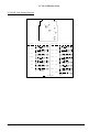
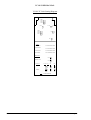
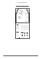
This section details the instrument connection information. Before proceeding, please check the
information on the serial number label on one side of the unit to ensure that the unit configuration
is correct. Connection details are given on a label on the opposite side of the unit, referring to
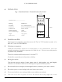
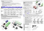
the numbered connector terminals as shown in fig.2 above.
3.1
Power Supply
The power supply is connected into terminals 1 (negative) and 2 (positive).
is indicated on the serial number label.
The supply voltage
APPLICATION OF VOLTAGES HIGHER THAN THAT STATED FOR THE SUPPLY
MAY CAUSE DAMAGE TO THE INSTRUMENT.
Ensure that no bare wire protrudes from the rear of the power connector risking a short circuit.
We advise the use of bootlace ferrules on all bare wires.
3.2
Sensor Connections
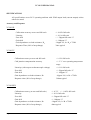
All sensor connections are made to terminals numbered 4, 5 and 6 on the instrument.
The inputs are connected as described below.
3.2.1
Voltage Inputs
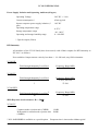
This applies to the high-level input device only (VCON-HL). The signal should be connected
between pins 5 (positive) and 4 (negative). The input voltage range is given on the serial
number label.
3.2.2
Current Inputs
This applies to the high-level input device only (VCON-HL). The signal should be connected
between pins 5 (positive) and 4 (negative). The input current range is given on the serial number
label. When the optional transmitter supply is used, the +ve of the transmitter is connected to
pin 3 and the return to pin 5. No other external links are required.
IIG-9501-03
Page 7