1
VCON USER MANUAL
VCON -TC
Accepts inputs directly from the following Thermocouple types: J, K, N, T, R, B, E, U, L and S,
alternatively a mV input may be specified. All specified ranges are zero referred - i.e. 0°F, 0°C
or 0 mV, although negative inputs will not damage the unit. Automatic cold junction
compensation will be fitted to thermocouple units, for which either upscale or downscale drive on
break detection are link selectable. The output is not linearised. For standard thermocouples
the operating range will be specified in °C or °F, as required. In general the limits on signals
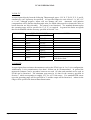
that can be handled with the accuracy specified in Section 7 are:
INPUT TYPE
mV
J(L)
K
T(U)
E
N
R
S
B
FULL SCALE INPUT
MIN
MAX
4mV
100mV
80°C
1200°C
100°C
1372°C
95°C
400°C
65°C
1000°C
150°C
1300°C
460°C
1768°C
480°C
1760°C
910°C
1820°C
NOTES
Cold junction compensation
will not be fitted
VCON-RTD
Accepts inputs from resistance thermometers such as the PT100 type in 2 or 3 wire configuration.
Additionally 2 wire potentiometers less than 1 Kohm can be accommodated. In general the
measured resistance can be anywhere between zero and 1 K ohm and standard curves such as
PT100 can be linearised. The minimum span must be 10 ohm for the accuracy specified in
Section 7, which corresponds to roughly 30°C for a PT 100 sensor. For standard RTD sensor
types the operating range will be specified in °C and the output will be linearised; otherwise the
range will be specified in ohms without linearisation.
Page 4
IIG-9501-03