1
MPC821ADS, Revision A - User’s Manual
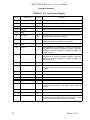
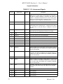
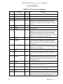
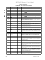
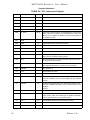
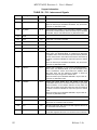
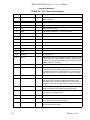
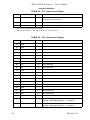
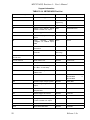
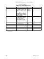
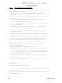
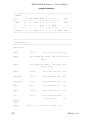
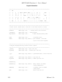
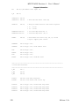
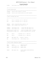
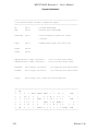
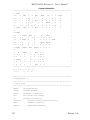
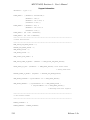
TABLE OF CONTENTS
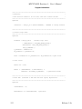
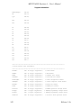
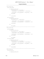
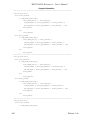
1 1•1
1•2
1•3
1•4
1•5
1•6
1•7
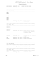
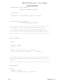
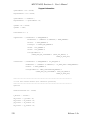
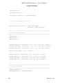
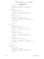
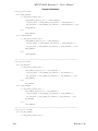
2 2•1
2•2
2•3
2•3•1
2•3•2
2•3•2•1
2•3•3
2•3•4
2•3•5
2•4
2•4•1
2•4•2
2•4•3
2•4•4
2•4•5
2•4•6
2•4•7
2•4•8
2•4•9
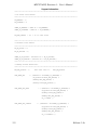
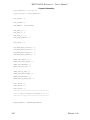
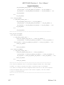
3 3•1
3•2
3•2•1
3•2•2
3•2•3
3•2•4
3•2•5
3•2•6
3•2•7
3•2•8
3•2•9
3•2•10
3•2•11
3•2•12
3•2•13
3•2•14
3•2•15
3•2•16
3•2•17
General Information
Introduction
Abbreviations’ List
Related Documentation
SPECIFICATIONS
MPC821ADS Features
Revision Pilot to Revision A Changes
Revision ENG to Revision PILOT Changes
Hardware Preparation and Installation
INTRODUCTION
UNPACKING INSTRUCTIONS
HARDWARE PREPARATION
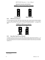
ADI Port Address Selection
Clock Source Selection
Clock Generator Replacement - U17
Power-On Reset Source Selection
VDDL Source Selection
Keep Alive Power Source Selection
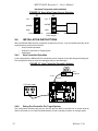
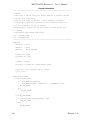
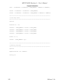
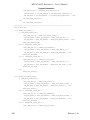
INSTALLATION INSTRUCTIONS
Host Controlled Operation
Debug Port Controller For Target System
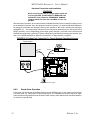
Stand Alone Operation
+5V Power Supply Connection
P8: +12V Power Supply Connection
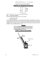
ADI Installation
Host computer to MPC821ADS Connection
Terminal to MPC821ADS RS-232 Connection
Memory Installation
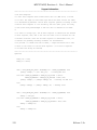
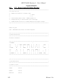
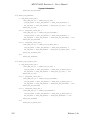
OPERATING INSTRUCTIONS
INTRODUCTION
CONTROLS AND INDICATORS
SOFT RESET Switch SW1
ABORT Switch SW2
HARD RESET - Switches SW1 & SW2
DS2 - Software Options Switch
J4 Power Bridge
GND Bridges
RUN Indicator - LD1
FLASH ON - LD2
DRAM ON - LD3
ETH ON - LD4
Ethernet RX Indicator - LD5
Ethernet TX Indicator - LD6
Ethernet JABB Indicator - LD7
IRD ON - LD8
Ethernet CLSN Indicator LD9
Ethernet PLR Indicator - LD10
Ethernet LIL Indicator - LD11
1
1
1
1
1
3
5
5
7
7
7
7
9
9
9
10
11
11
12
12
12
13
14
14
15
15
15
16
17
17
17
17
17
17
17
18
18
18
18
18
18
18
18
18
18
19
19
19
Release 1.3a
Thi d
t
t d ith F
M k
404