1
MPC821ADS, Revision A - User’s Manual
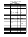
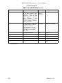
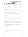
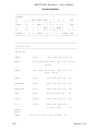
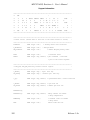
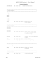
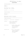
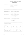
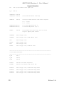
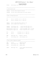
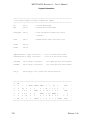
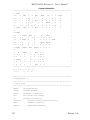
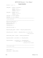
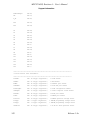
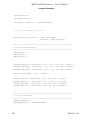
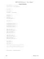
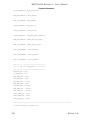
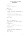
TABLE OF CONTENTS
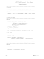
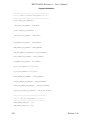
3•2•18
3•2•19
3•2•20
3•2•21
RS232 ON - LD12
PCMCIA ON - LD13
5V Indicator - LD14
3.3V Indicator - LD15
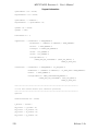
3•3
MEMORY MAP
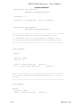
3•4
Programming The MPC Registers
3•4•1
Memory Controller Registers Programming
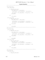
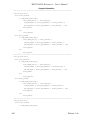
4 Functional Description
4•1
MPC821 Or MPC860
4•2
Reset & Reset - Configuration
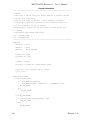
4•2•1
Keep Alive Power-On Reset
4•2•2
Main Power - On Reset
4•2•3
Manual Soft Reset
4•2•4
Manual Hard Reset
4•2•5
MPC Internal Sources
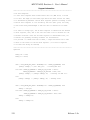
4•2•6
Reset Configuration
4•2•6•1 Power - On Reset Configuration
4•2•6•2 Hard Reset Configuration
4•2•6•3 Soft Reset Configuration
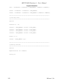
4•3
Local Interrupter
4•4
Clock Generator
4•4•1
SPLL Support
4•5
Buffering
4•6
Chip - Select Generator
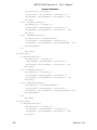
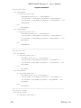
4•7
DRAM
4•7•1
DRAM 16 Bit Operation
4•7•2
DRAM Performance Figures
4•7•3
Refresh Control
4•7•4
Variable Bus-Width Control
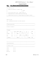
4•8
Flash Memory
4•9
Ethernet Port
4•10
Infra - Red Port
4•11
RS232 Port
4•11•1
RS-232 Port Signal Description
4•12
PCMCIA Port
4•12•1
PCMCIA Power Control
4•13
LCD Port
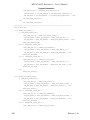
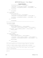
4•14
Board Control & Status Register - BCSR
4•14•1
BCSR Disable Protection Logic
4•14•2
BCSR0 - Hard Reset Configuration Register
4•14•3
BCSR1 - Board Control Register
4•14•4
BCSR2 - Board Status Register - 1
4•14•5
BCSR3 - Auxiliary Control / Status Register
4•15
Debug Port Controller
4•15•1
MPC821ADS As Debug Port Controller For Target System
4•15•1•1 Debug Port Connection - Target System Requirements
4•15•2
Debug Port Control / Status Register
4•15•3
Standard MPCXXX Debug Port Connector Pin Description
Release 1.3a
19
19
19
19
20
20
21
34
34
34
34
34
34
35
35
35
35
35
36
36
37
37
37
37
38
38
39
40
41
42
44
44
45
45
45
46
46
48
48
48
49
51
53
56
56
57
57
58