1
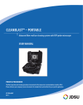
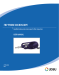
BOEING 787: Fiber Inspection and Cleaning Inspect with FBP Probe and HD-series Display; Clean with CleanBlast System User Manual ZP-PKG-0554 REV 0 Notice Every effort was made to ensure that the information in this document was accurate at the time of printing. However, information is subject to change without notice, and JDSU reserves the right to provide an addendum to this document with information not available at the time that this document was created. Copyright © Copyright 2010 JDSU, LLC. All rights reserved. JDSU, Enabling Broadband and Optical Innovation, and its logo are trademarks of JDSU, LLC. All other trademarks and registered trademarks are the property of their respective owners. No part of this guide may be reproduced or transmitted electronically or otherwise without written permission of the publisher. Trademarks JDSU is a trademark of JDSU in the United States and other countries. CleanBlast is a registered trademark of JDSU. RibbonDrive is a trademark of JDSU. Hirose is a trademark of Hirose Electric Group. MTP is a registered trademark of US Conec, Ltd. IBC is a trademark of US Conec, Ltd. Molex is a registered trademark of Molex Incorporated. OptiTip and OptiTap are trademarks of Corning Incorporated. Sony is a registered trademark of Sony Corporation. Specifications, terms, and conditions are subject to change without notice. All trademarks and registered trademarks are the property of their respective companies. Patents RibbonDrive Tips: US Patent No. 6,751,017 / 6,879,439 CleanBlast: US Patent No. 7,232.262 Tested Equipment ii All pre-qualification tests were performed internally at JDSU, while all final tests were performed externally at an independent, accredited laboratory. This external testing guarantees the unerring objectivity and authoritative compliance of all test results. JDSU's Commerce and Government Entities (CAGE) code under the North Atlantic Treaty Organization (NATO) is 0L8C3. FCC Information Electronic test equipment is exempt from Part 15 compliance (FCC) in the United States. European Union Electronic test equipment is subject to the EMC Directive in the European Union. The EN61326 standard prescribes both emission and immunity requirements for laboratory, measurement, and control equipment. This unit has been tested and found to comply with the limits for a Class A digital device. Independent Laboratory Testing This unit has undergone extensive testing according to the European Union Directive and Standards. Contents Introduction to Fiber Inspection Fiber Inspection Overview........................................................................4 Inspect Before You Connect.....................................................................4 Benefits of Proactive Inspection...........................................................4 Fiber Optic Connectors Single Fiber Connectors..............................................................................5 Mil-Aero Connectors ARINC 801.............................................................................................................6 Key Terms...............................................................................................................6 JDSU Alignment Guides..............................................................................6 Effect on Signal Performance The Problem........................................................................................................7 Inspect Before You Connect The Solution........................................................................................................8 Proactive Inspection vs. Reactive Inspection..............................8 Where Inspection Should Occur Inspect at Every Stage of Handling Fiber.......................................9 INSPECT Inspect Inspect: Bulkhead (Single Fiber Connectors)............................10 Inspect: Patch Cord (Single Fiber Connectors)........................11 Inspect: ARINC Receptacle (Mil-Aero)............................................12 Inspect: ARINC Plug (Mil-Aero)............................................................13 CLEAN Clean Connect Clean: Common Methods.......................................................................14 Clean: JDSU CleanBlast System..........................................................15 CONNECT Good Fiber Connection............................................................................16 FBP Probe Microscope FBP Probe Overview...................................................................................17 Specifications..................................................................................................17 Inspection Tips, Guides, Barrel Assemblies Inspection Tips and Guides...................................................................18 Barrel Assemblies..........................................................................................18 Tips, Guides, and Barrel Assemblies Map Tips/Guide Installation Guide..............................................................19 HD1 Video Display HD1 Display Overview..............................................................................20 Specifications..................................................................................................20 FBP3 Long Reach Probe and Tips FBP3 Probe Overview................................................................................21 FBP3 Tips and Barrel Assembly...........................................................21 JDSU CleanBlast System CleanBlast System Overview................................................................22 Boeing 787 Configurations Configurations Table..................................................................................23 BOEING 787: Fiber Inspection and Cleaning iii Introduction to Fiber Inspection Fiber Inspection Overview Contamination is the number 1 reason for troubleshooting optical networks. A single particle mated into the core of a fiber can cause significant back reflection, insertion loss, and equipment damage. Visual inspection is the only way to determine if fiber connectors are truly clean before mating them. The JDSU video fiber inspection probe and handheld display system is used to quickly and easily inspect connector end faces, which ultimately minimizes signal loss and optimizes test conditions. FBP-series video probes are dual-magnification (200/400X), high-performance handheld microscopes designed for inspecting both female (bulkhead) and male (patch cord) connectors. The probe microscope can also be combined with a USB converter module to inspect connectors via compatible test platforms and PC/laptop. This versatile system offers a wide range of configurable solutions that can meet the demands of any application. Our comprehensive selection of precision, stainless-steel fiber inspection tips, adapters, and guides are carefully engineered to produce consistent and accurate results. They are interchangeable and designed with a unique optics architecture that enables the probe to interface with every connector and application in your network. Inspect Before You Connect Implementing a simple yet important process of proactively inspecting and cleaning before mating can prevent poor signal performance and equipment damage. Benefits of Proactive Inspection Proactively inspecting fiber optic connectors will... Reduce Aircraft On Ground (AOG) Instances Reduce Troubleshooting Optimize Signal Performance Prevent Damage to Network Hardware 4 User Manual Fiber Optic Connectors Single Fiber Connectors Also called simplex connectors, these types contain a single fiber located in the center of a ceramic zirconia ferrule. The alignment of the mated connectors/fibers is achieved inside a ceramic or bronze mating sleeve within the bulkhead adapter. Body Body LC Connector Houses the ferrule that secures the fiber in place; utilizes a latch and key mechanism that aligns the fiber and prevents the rotation of ferrules of two mated connectors. Core Cladding Ferrule Ferrule Thin cylinder where the fiber is mounted that acts as the fiber alignment mechanism; the end of the fiber is located at the end of the ferrule. Fiber Cladding Glass layer surrounding the core that prevents the signal in the core from escaping. Core The critical center layer of the fiber; the conduit that light passes through. Fiber Ferrule Alignment Sleeve Fiber Connection (Simplex) Physical Contact BOEING 787: Fiber Inspection and Cleaning 5 Mil-Aero Connectors Receptacle ARINC 801 Mil-Aero connectors are fiber optic connectors used in aerospace applications. Established by the Airlines Electronic Engineering Committee (AEEC), ARINC 801 is part of the ARINC 800 series of fiber optic standards for avionics networking. All ARINC 801 connectors utilize a 1.25 mm ferrule and are mated in a pin and socket configuration. While all of the ARINC 801 connectors utilize a “plug and receptacle” design, there are different design types within the standard. Alignment Guide FBP Probe Microscope Key Terms Plug: The male interface of an ARINC 801 connection. Receptacle: The female interface of an ARINC 801 connection. Pin: The exposed 1.25 mm ferrule. Socket: The unexposed ferrule inside the alignment sleeve. Plug Pin JDSU Alignment Guides JDSU offers a series of alignment guides that fit the shell sizes of the respective plug and receptacle of various ARINC 801 connectors. These guides provide a compatible interface for the inspection and cleaning of pins or sockets specific to each type of connector. With the JDSU FBP probe microscope and handheld video display, JDSU's ARINC 801 alignment guides provide the means for a quick and easy inspection of these rugged, multi-termini connectors, in a field or factory environment. In addition, these guides can also be used with the JDSU CleanBlast™ system to clean away debris and dirt from the optical end-faces of ARINC 801 connectivity. 6 Socket User Manual Socket Receptacle Effect on Signal Performance The Problem Dirt is everywhere, and a typical dust particle (2–15 μm in diameter) can significantly affect signal performance and cause permanent damage to the fiber end face. Most field test failures can be attributed to dirty connectors, and most of them are not inspected until the problem is detected, after permanent damage has already occurred. When dirt particles get on the core surface, light becomes blocked, creating unacceptable insertion loss and back-reflection. Furthermore, these contamination particles can permanently damage the glass interface by digging into the glass and leaving pits when mated, causing further signal loss. Damage also occurs when large particles of dirt on the cladding layer and/or the ferrule cause barriers that prevent physical contact, creating air gaps between the fiber connection. These large particles are also known to break apart and migrate across the fiber surface when mated. Dirty Fiber Light Transmitted Core BOEING 787: Fiber Inspection and Cleaning Cladding Back Reflection Insertion Loss DIRTY CONNECTION 7 INSPeCT BEFORE YOU CONNECT The Solution Inspect Before You Connect By implementing a simple yet important process of proactively inspecting and cleaning before mating, you can prevent poor signal performance and equipment damage. Proactive Inspection Loose debris and dirt are much easier to clean prior to mating the 2 connector sides. By visually inspecting fiber connectors at every stage of handling before mating them, you are proactive in preventing signal loss and equipment damage. Connectors are much easier to clean prior to mating, before embedding debris into the fiber. Dirty Fiber – Prior to Mating Cleaned Fiber – Before Embedding Debris Reactive Inspection If dirty connectors are not inspected and cleaned prior to mating, dirt and debris can embed into the fiber surface causing permanent damage. By visually inspecting after a problem is discovered, you are taking a reactive approach. By this time, connectors and other equipment may have suffered permanent damage. Dirty Fiber – Prior to Mating Cleaned Fiber with Embedded Debris After Mating and Multiple Cleanings Embedded debris cannot be removed or cleaned! 8 User Manual Where Inspection Should Occur Inspection of fiber end faces is CRITICAL at EVERY STAGE of handling fiber. Connector Manufacturing Harness Test BOEING 787: Fiber Inspection and Cleaning Aircraft Assembly Maintenance Flight Line 9 INSPECT: Bulkhead (Single Fiber Connectors) INSPECT Install Tip and Barrel Assembly 1. Install the appropriate inspection tip and barrel assembly (FBPP-BAP1) to the probe microscope. Note: Standard tips require barrel assembly. 1 Inspection Tip Barrel Assembly Inspect Bulkhead 2. 3. 4. Insert the probe into the bulkhead to inspect. 3 Turn the focus control on the probe to focus the fiber image on the display. 2 Determine whether clean or dirty. If clean, do not touch it and CONNECT. Focus Control If dirty, and if cleaning is required, CLEAN. 10 4 User Manual INSPECT: Patch Cord (Single Fiber Connectors) INSPECT Install Tip and Barrel Assembly 1. Install the appropriate inspection tip and barrel assembly (FBPP-BAP1) to the probe microscope. Note: Standard tips require barrel assembly. 1 Inspection Tip Barrel Assembly Inspect Patch Cord 2. 3. 4. Attach the patch cord to the probe microscope to inspect. 2 3 Turn the focus control on the probe to focus the fiber image on the display. Determine whether clean or dirty. Focus Control If clean, do not touch it and CONNECT. If dirty, and if cleaning is required, CLEAN. BOEING 787: Fiber Inspection and Cleaning 4 11 INSPECT: ARINC Receptacle (Mil-Aero) INSPECT Install Barrel Assembly / Tip 1. Install the barrel assembly (FBPP-BAP3 or FBPP-BAP3-A6) to the probe microscope. Note: No additional inspection tip is necessary when using guides. 1 Barrel Assembly (FBPP-BAP3 shown) 2. Align the ARINC alignment guide for receptacle (FBPT-A801-2002R) and insert into either side of the receptacle (pins or socket). Alignment Guide (FBPT-A801-2002R) Inspect 3. 4. 5. 3 Insert the probe into the alignment guide to inspect. Turn the focus control on the probe to focus the fiber image on the display. 4 Determine whether clean or dirty. 5 If clean, do not touch it and CONNECT. Focus Control If dirty, and if cleaning is required, CLEAN. 12 Note: For Cleanliness Acceptance Criteria, see the Aircraft Maintenance Manual (AMM) for the Boeing 787. HD1 Video Display User Manual INSPECT: ARINC Plug (Mil-Aero) INSPECT Install Barrel Assembly / Tip 1. Install the barrel assembly (FBPP-BAP3 or FBPP-BAP3-A6) to the probe microscope. Note: No additional inspection tip is necessary when using guides. 1 Barrel Assembly (FBPP-BAP3 shown) 2. Align the ARINC alignment guide for plug (FBPT-A801-2001P) and insert into either side of the receptacle (pins or socket). Alignment Guide (FBPT-A801-2001P) Inspect 3. 4. 5. 3 Insert the probe into the alignment guide to inspect. Turn the focus control on the probe to focus the fiber image on the display. Determine whether clean or dirty. If clean, do not touch it and CONNECT. 4 5 Focus Control If dirty, and if cleaning is required, CLEAN. Note: For Cleanliness Acceptance Criteria, see the Aircraft Maintenance Manual (AMM) for the Boeing 787. BOEING 787: Fiber Inspection and Cleaning HD1 Video Display 13 Clean: Common Methods CLEAN Note: For Cleanliness Acceptance Criteria, see the Aircraft Maintenance Manual (AMM) for the Boeing 787. Clean Bulkhead Swab Use the swab to clean the bulkhead by inserting into bulkhead, applying slight pressure, and twisting the swab 2 to 3 times. Inspect again, and repeat if necessary. Note: Be sure to follow the recommended cleaning procedures defined in the Aircraft Maintenance Manual (AMM). Clean Patch Cord REEL-STYLE Cleaners or Cloths When cleaning with the reel-style cleaners or cleaning cloths, push the latch lever to expose the cleaning area/ cloth and wipe the patch cord end along the cleaning cloth in the direction of the indicated arrow 2 to 3 times. Note: Be sure to follow the recommended cleaning procedures defined in the Aircraft Maintenance Manual (AMM). Reuseable Cleaning Stick Reuseable cleaning sticks clean both the bulkhead and patch cord sides. 14 User Manual Clean: JDSU CleanBlast™ System CLEAN Cleaning With CleanBlast To clean receptacles with the CleanBlast system: Run Button 1. Install the appropriate cleaning tip to the CleanBlast handset. Cleaning Tip 1 2.PRIME the nozzle if necessary (see CleanBlast User Manual). 3. Align the alignment guide and insert into either side of the receptacle or plug (pins or socket). 3 4. Insert the handset into the alignment guide and push to disengage safety mechanism (the POWER/READY light will turn green), and press the run button to initiate cleaning. 5. INSPECT the receptacle or plug. 6. Determine whether clean or dirty. Alignment Guide (FBPT-A801-2002R) 4 If clean, do not touch it and CONNECT. If dirty, repeat CLEAN. Note: Embedded/mated debris cannot be cleaned, and bonded/burned debris must be physically cleaned before using CleanBlast. 5 6 Focus Control BOEING 787: Fiber Inspection and Cleaning 15 Connect CONNECT Good Fiber Connection There are 3 basic principles that are critical to achieving an efficient fiber optic connection: 1. 2. 3. Perfect Core Alignment Physical Contact Pristine Connector Interface Light Transmitted Cladding Core Clean Connection Today’s connector design and production techniques have eliminated most of the challenges to achieving core alignment and physical contact. What remains challenging is maintaining a pristine end face. As a result, CONTAMINATION is the #1 reason for troubleshooting optical networks. Systematic and Proactive Inspection is the only way to ensure that the connectors are truly clean before mating them. INSPECT BEFORE YOU CONNECT. 16 User Manual FBP Probe Microscope FBP Probe Overview JDSU FBP-series probes are portable video microscopes used to inspect fiber optic connectivity. While most fiber microscopes are limited to inspecting male connectors, JDSU's FBP probe is designed to inspect both simplex and multi-fiber (ribbon) types of both male and female connectors, as well as optical devices such as transceivers. The probe is specially designed to fit and operate comfortably and easily in-hand, allowing the user to inspect hardto-reach connectors that are installed on the backside of patch panels or inside hardware devices. This eliminates the need to disassemble hardware devices prior to inspection. Focus Control Magnification Control Inspection Tip Barrel Assembly Controls The focus control on the probe allows the user to adjust focus manually of the live fiber end face image on the display. The magnification control (available only on dualmagnification probes) allows the user to switch between LOW and HIGH magnifications of the fiber end face image. BOEING 787: Fiber Inspection and Cleaning Specifications Dimensions 140 x 46 x 43 mm (5.5 x 1.8 x 1.7 in) Weight 180 g (6.3 oz) Optical magnification 200X, 400X, 200/400X Focus control Adjustable, in-probe Cord length 240 cm (94-in) Connector 4-pin Hirose™ male Camera type 1/3-in CMOS Sensor Video output NTSC or PAL Light source Blue LED, 100,000+ hour life Lighting technique Coaxial Power source From the display device or USB module 17 JDSU Inspection Tips, Guides, Barrel Assemblies Inspection Tips and Guides To optimize the performance and safety of fiber inspection, the probe microscope is used in conjunction with various interchangeable tips and guides. Each tip or guide is specifically designed to accessibility and accurate inspection for every connector on the aircraft without causing harm to the connections. FBPT-SC FBPT-U25M FBPT-A801-2001R Standard Bulkhead Tips Standard bulkhead tips allow the user to inspect the fiber end face on the female side of the bulkhead (e.g., inside hardware devices or on the back side of patch panels). Standard Bulkhead Tips Standard patch cord tips allow inspection of male ends of a fiber connection (e.g., patch cords, pigtails). Universal tips include the FBPT-U25M, compatible with 2.5 mm ferrules (e.g., FC, SC, ST) and the FBPT-U12M, used to inspect 1.25 mm ferrules (e.g., LC, MU). Alignment Guides Alignment guides enable the inspection of various military and aerospace connectors that use a plug and receptacle design. In addition to providing an alignment channel for sockets, these alignment guides work in conjunction with a barrel assembly to prevent the pins from breaking. Barrel Assemblies The barrel assembly houses the objective lens and works in conjunction with various FBPT inspection tips and alignment guides. 18 FBPP-BAP1 User Manual FBPP-BAP3 FBPP-BAP3-A6 Tips, Guides, and Barrel Assemblies Map Tips/Guide Installation Guide FBPT Inspection Tips Barrel Assembly Standard Patch Cord Tips FBPP-BAP1 Standard Bulkhead Tips Alignment Guides FBP Probe Microscope FBPP-BAP3 Description FBPP-BAP1 Attach this barrel assembly directly onto the P5 probe and use with the various inspection tips for inspecting fiber connectors. FBPP-BAP3 Attach this barrel assembly directly onto the P5 probe and use with the various alignment guides for inspecting avionics fiber connectors. FBPP-BAP3-A6 Typical Use: Inspecting the Tray side of the AGU. Attach this angled narrow barrel assembly directly onto the P5 probe and use with the various alignment guides for inspecting avionics fiber connectors. The 60 degree angle allows access into tight areas, such as the AGU tray. FBPT-C130 FBPT-C130 Attach this tip directly onto the P5 probe and use with select alignment guides. Typical Use: Inspecting the Receptacle in the back tray of a CCR Cabinet. FBP3-C130 Attach this tip on the end o the Long Reach Video Probe (P3), for use with select alignment guides. FBPP-BAP3-A6 FBP3 Long Reach Probe Microscope BOEING 787: Fiber Inspection and Cleaning Alignment Guides FBP3-C130 Typical Use: Inspecting the Receptacle in the back tray of a CCR Cabinet. 19 HD1 Video Display HD1 display Overview The JDSU HD1 Video Display is a durable, lightweight, ergonomic, drop-tested display for use with any NTSC FBP or FBP3 series probe. It features a 3.5-inch TFT active matrix LCD screen, which produces a bright, clear and crisp, high-contrast image of the fiber end face. It can be powered by 100–240V AC or a rechargeable Li-on battery (the Li-on battery must be in the display for the unit to operate). The HD1 Display features contrast adjustment, auto-shutoff function to preserve battery life, and a hanging accessory for hands-free operation. The display uses a 4-pin Hirose™ connector, which routes power into the probe and video out of the probe. A conversion cable is also available for 6-pin QuickCapture™ analog probes. 3.5-inch TFT LCD Screen ON/OFF Control Battery Power LED Auto Shut-down Interval and Contrast Control AC Power LED Battery Status and Auto Shut-down Interval LED's Features • 3.5-inch TFT LCD display • Contrast control/adjustment • Rechargeable Sony® Li-ion battery with 2 hours Hanging Accessory continuous run time (extended when using auto-shutoff feature) Removable Magnet (Optional) • Battery gauge (LED) showing remaining battery life • Built-in hanging accessory for hands-free operation Rechargeable Li-on Battery Specifications Dimensions 45.7 x 43.2 x 140 mm Weight 400 g Video display 3.5-inch TFT LCD Connectors 4-pin for FBP probe microscopes Battery life 2-hours continuous use Charging time 2-hours 20 4-pin connector to Probe User Manual AC Power Input FBP3 Long Reach Probe and Tips FBP3 Probe Overview As system capacities have increased, optical connectors have proliferated in backplane applications. Increasingly, those connectors are ribbon ferrule based. The FBP3 series is purpose-built for reaching between adjacent cards/ modules to reach optical connectors in the backplane. The FBP3-P3L is a long-reach backplane probe that is designed to inspect connectors that are otherwise difficult to access. Its unique and complimentary design allows the probe to fit down a channel less than 1-inch wide, making the inspecti0n of backplanes convenient and functional. The Universal Adapter is compatible with all standard FBPT-series inspection tips. This allows the probe to inspect a broad range of connector types located in... The 4-pin connector output interfaces with the HD1 handheld video display. The design of the FBP3-BLX probe incorporates an imaging system, integrated light source, video camera and focus mechanism. The handle and barrel components of the probe are easily assembled and is powered by the HD1 display. Handle Barrel Focus Control 4-pin Connection to HD1 Display FBP3 Tips and Barrel Assembly Tips and barrel assemblies such as the FBP3-C130 are specifically designed to work with the FBP3 long reach probe microscope, and are typically used to inspect receptacles in the back tray of CCR cabinets. BOEING 787: Fiber Inspection and Cleaning FBP3-C130 21 JDSU CleanBlast System CleanBlast System Overview The patented JDSU CleanBlast fiber end face cleaning systems provide a fast, effective, and cost-efficient solution for removing dirt and debris from connectors in most common applications. CleanBlast is a noncontact system that uses a highly filtered stream of pressurized gas with a vacuum circuit to create a high flow rate jet across the surface of the fiber. A cleaning solvent is injected into the airflow, and the contamination from the end face along with the solvent are then removed through the retrieval circuit. The precise, highly efficient non-contact airsolvent-air stream blasts and removes loose debris with nearly 100-percent effectiveness. CONTAMINATION MUST BE CLEANED from the end face prior to mating in order to optimize the efficiency of an optical signal or interconnect. CleanBlast eliminates the user sensitivity and inconsistencies experienced with other cleaning tools by removing loose debris at the push of a button. With more than 8,000 cleaning cycles between refills, this automated system cleans faster, more effectively, and is less cost-per-clean than conventional methods. • Faster, more effective, and less cost per clean than using other methods • Provides repeatable results • Eliminates user sensitivity • Removes (instead of spreading) loose debris from fiber optic end-faces • Cleans both patch cords and bulkheads • Multiple system configurations for a variety of applications • Clean multiple connector types by changing the precision cleaning tips 22 User Manual Boeing 787 Configurations FBP-787-1 Part Number FBP-HD1 FBP-P5-H FBPT-C130 FBPP-BAP3 FBPP-BAP3-A6 FBPT-A801-1002R FBPT-A801-1002P FBPT-A801-4001P FBPT-A801-2001P FBPT-A801-2001R FBPT-A801-2002R FBPT-A801-2002P FBPT-LUX24-G001 FBPT-LUX24-G002 FBPT-U12M FBPT-U25M FBPT-SC FBPT-LC FBPP-HSC15 FBPP-TACS1 FBPP-TACS2 Boeing 787 - Basic Avionics Inspection Kit Qty 1 1 1 1 1 1 1 1 1 1 1 1 1 1 1 1 1 1 1 1 1 FBP-787-CCR FBP3-P3L FBP3-C130 Description HD1 - Handheld Video Display, 3.5-inch LCD P5 Probe - Video Inspection Probe, 200/400X, EMI Hardened, 4-pin Out Interface Tip, for Standard Video Probe (P5), for Use with Locking Guides Barrel Assembly, for P5 Probe, Narrow Type, for Use with Guides Barrel Assembly, for P5 Probe, Narrow Type w/ 60° Angle, for Use with Guides Guide, ARINC Type 1, Size 15-06 Shell, Receptacle w/ Pins Guide, ARINC Type 1, Size 15-06 Shell, Plug w/ Sockets Guide, ARINC Type 4, 12 Contact, Plug w/ Pins Guide, ARINC Type 2, F12, Plug w/ Pins Guide, ARINC Type 2, F12, Receptacle w/ Sockets Guide, ARINC Type 2, F12, Receptacle w/ Pins Guide, ARINC Type 2, F12, Plug w/ Sockets Guide, LUXCIS 24-In Line, Plug w/ Sockets Guide, LUXCIS 24-In Line, Receptacle w/ Pins Tip, Universal 1.25 mm Patch Cord Tip, Universal 2.5 mm Patch Cord Tip, SC Bulkhead Tip, LC Bulkhead Pelican 1550 Case with Custom Foam for 787 Kit Tip Case with Dividers - for Boeing 787 Guides Tip Case with Foam - for Boeing 787 Tips and Barrel Assemblies Boeing 787 - CCR Cabinet - Long Reach Upgrade Kit 1 1 FCL-ARINC-01 P3 Probe - Video Inspection Probe, Long Reach Handle and Barrel Interface Tip, for Long Reach Video Probe (P3), for Use with Locking Guides Inspection and Cleaning Kit - ARINC FCL-P1102 FCLT-BAP3-125 FBP-P5 FBPP-BAP3 FBPT-A801-1002R FBPT-A801-1002P FBPT-A801-2001P FBPT-A801-2001R FBPT-A801-2002R FBPT-A801-2002P FBPT-A801-4001P FBPT-A801-4001R FBPP-DPAC2 1 1 1 1 1 1 1 1 1 1 1 1 1 FBPT-A801-4002P FBPT-A801-4002R 1 1 FBPT-RQX8-P FBPT-RQX8-S FBPT-A801-1001R FBPT-A801-1001P 1 1 1 1 FCLT-C130 1 CleanBlast, Portable System, Digital Cleaning Tip, ARINC Guides P5 Probe - Video Inspection Probe, 200/400X, 4-pin Out Barrel Assembly, Narrow Type Guide, ARINC Type 1, Size 15-06 Shell, Receptacle w/ Pins Guide, ARINC Type 1, Size 15-06 Shell, Plug w/ Sockets Guide, ARINC Type 2, F12, Plug w/ Pins Guide, ARINC Type 2, F12, Receptacle w/ Sockets Guide, ARINC Type 2, F12, Receptacle w/ Pins Guide, ARINC Type 2, F12, Plug w/ Sockets Guide, ARINC Type 4, 12 Contact, Plug w/ Pins Guide, ARINC Type 4, 12 Contact, Receptacle w/ Sockets Converter Cable, 4-pin Probe Boeing 787 - In-Flight Entertainment (PANASONIC) - Inspection Tips Guide, ARINC Type 4, 36 Contact, Plug w/ Pins Guide, ARINC Type 4, 36 Contact, Receptacle w/ Sockets Boeing 787 - In-Flight Entertainment (THALES) - Inspection Tips Tip, Radiall Quadrax, Size 8, Pin Tip, Radiall Quadrax, Size 8, Socket Guide, ARINC Type 1, Size 13-04 Shell, Receptacle w/ Pins Guide, ARINC Type 1, Size 13-04 Shell, Plug w/ Sockets Miscellaneous Accessories Cleaning Tip, for CleanBlast System, Rugged, for LUX24 Guides BOEING 787: Fiber Inspection and Cleaning 23 Test and Measurement Regional Sales NORTH AMERICA TEL:1 866 228 3762 FAX:1 301 353 9216 LATIN AMERICA TEL:+1 954 688 5660 FAX:+1 954 345 4668 ASIA PACIFIC TEL:+852 2892 0990 FAX:+852 2892 0770 EMEA TEL:+49 7121 86 2222 FAX:+49 7181 86 1222 www.jdsu.com/inspect Product specifications and descriptions in this document subject to change without notice. © 2010 JDS Uniphase Corporation. August 2010 ZP-PKG-0554 REV 0