1
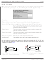
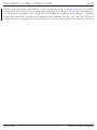
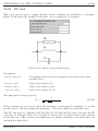
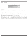
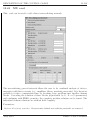
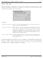
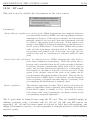
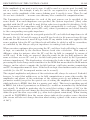
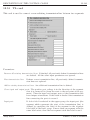
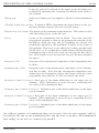
FEKO
User’s Manual
Suite 5.3
July 2007
Copyright 1998 – 2007: EM Software & Systems-S.A. (Pty) Ltd
32 Techno Avenue, Technopark, Stellenbosch, 7600, South Africa
Tel: +27-21-880-1880, Fax: +27-21-880-1936
E-Mail: [email protected]
WWW: http://www.feko.info
DESCRIPTION OF THE CONTROL CARDS
12.38
12-114
LN card
This card can be used to add a complex load to any non-radiating network port that is
not connected to geometry (i.e. any non-radiating network of the type Internal).
Parameters:
Define a load at a network port: Define a network load with the following parameters.
Remove all LN type loads previously defined: All previously defined LN type loads are removed. This replaces all network loads with open circuits. Note
that setting the load impedance to zero creates a short circuit
between the network terminals.
Network name:
The network name, with the network port number, uniquely identifies the connection terminals.
Network port number:
The network port number, with the network name, uniquely identifies the connection terminals.
Real part of impedance:
The real part of the complex impedance in Ω.
Imaginary part:
The imaginary part value of the complex impedance in Ω.
For the loading of network ports connected to MoM wire segments, the LZ, LS, LP and
LD type loads are supported. These loads are placed in series with the port connection
as indicated in Figure 12-27.
Figure 12-27: Normal load placement.
July 2007
Figure 12-28: Load placement for S-parameter
calculations.
FEKO User’s Manual
DESCRIPTION OF THE CONTROL CARDS
12-115
When a network port corresponds to an S-parameter port, however, the use of an additional LZ load on that port segment is prohibited (see Figure 12-28). In this instance,
for MoM wire segments, there is in effect no difference between the Adding to existing
loads and Replacing existing loads option when defining the SP-card. For the LN-card,
however, these two options do have an effect because of the specific placement of the load.
July 2007
FEKO User’s Manual
DESCRIPTION OF THE CONTROL CARDS
12.39
12-116
LP card
This card can be used to assign discrete circuit elements (in parallel) to a segment.
Figure 12-29 shows the parallel circuit that can be assigned to a segment.
Figure 12-29: Sketch of the parallel circuit
Parameters:
Label of segments . . .:
All segments with this label are assigned the parallel circuit values
specified below.
Resistor value:
Value of the resistor in Ω.
Inductor value:
Value of the inductor in H.
Capacitor value :
Value of the capacitor in F.
The impedance is then given by
Zp =
1
1
Rp
+
1
jωLp
+ jωCp
.
(12-66)
If the resistance is set to zero, then the resistance is interpreted as infinite, i.e. in the
parallel case it will not change the impedance. The same applies to the inductance.
The LP card may be combined with the LD, LS, LZ and the SK cards, but only one LP
card may be used per label. If a second LP card is used, it replaces the values entered
by the first one. This card has no significance for surface elements, even when these are
assigned the same label.
July 2007
FEKO User’s Manual
DESCRIPTION OF THE CONTROL CARDS
12.40
12-117
LS card
This card can be used to assign discrete circuit elements (in series) to a segment.
Figure 12-30 shows this circuit that can be assigned to a segment.
Figure 12-30: Sketch for the serial combination
Parameters:
Label of segments . . .:
All segments with this label are assigned the series circuit values
specified below.
Resistor value:
Value of the resistor in Ω.
Inductor value:
Value of the inductor in H.
Capacitor value:
Value of the capacitor in F.
The impedance is given by
Zs = Rs + jωLs +
1
.
jωCs
(12-67)
If a capacitance of zero is selected, it is interpreted as infinite capacitance, i.e. in the case
of the series combination it is zero.
The LS card may be combined with the LD, LP, LZ and the SK cards, but only one LS
card may be used per label. If a second LS card is used, it replaces the values entered
by the first one. This card has no significance for surface elements, even when these are
assigned the same label.
July 2007
FEKO User’s Manual
DESCRIPTION OF THE CONTROL CARDS
12.41
12-118
LZ card
This card can be used to assign a complex impedance to a segment.
Parameters:
Label of segments . . .:
All segments with this label are assigned the specified impedance.
Real part of impedance:
The real part of the complex impedance in Ω.
Imaginary part:
The imaginary part value of the complex impedance in Ω.
The complex impedance value is a constant with respect to frequency. Frequency dependent impedances can be realised using the LS or the LP cards.
The LZ card may be combined with the LD, LP, LS and the SK cards, but only one LZ
card may be used per label. If a second LZ card is used, it replaces the values entered
by the first one. This card has no significance for surface elements, even when these are
assigned the same label.
July 2007
FEKO User’s Manual
DESCRIPTION OF THE CONTROL CARDS
12.42
12-119
NW card
This card can be used to add a linear non-radiating network.
The non-radiating general network allows the user to do combined analysis of electromagnetics with linear circuits (e.g. amplifiers, filters, matching networks). It is therefore
possible to reduce computation time by breaking large problems into smaller element
blocks. Cascading the solution of these blocks (represented by S-, Z- or Y-parameters)
and combining with FEKO geometry, the complete problem solution can be found. The
individual element solutions are without field coupling.
Parameters:
Remove all existing networks: All previously defined non-radiating networks are removed.
July 2007
FEKO User’s Manual
DESCRIPTION OF THE CONTROL CARDS
New network:
12-120
A new non-radiating network is created after removing all previously defined networks.
Add to existing network: A non-radiating network is created and added to any previously
defined networks.
Network name:
The name of the network.
Number of ports:
A network can consist of any number of ports, but is required to
have at least one port.
Port n:
For each port of a network can be connected to other networks or
MOM wire segments.
Specify label The label of the segment to which the network
port must be connected. If more than one segment has this
label, the network port is connected to the last segment with
this label.
Specify position The segment is determined by specifying the
Cartesian coordinates of the segment centre. These values
are in metre and are scaled by the SF card if Modify all
dimension related values is checked.
Internal port The network name and the network port number
of an other network port that that has to be connected.
Data type:
The network data can be specified S-parameters, Z-parameters or
Y-parameters.
Load data from Touchstone file: The network data can be loaded from a Touchstone file.
The data in a Touchstone file is always defined in increasing order
and at specific frequencies only. These may of course not directly
coincide with the frequencies at which the FEKO kernel is run.
The solution is to interpolate both the magnitude and phase data
by using cubic spline interpolation. The FEKO frequency is considered out of bounds when it is more than 0.1% away from the
lowest/highest frequency defined in the Touchstone file. In such
an instance an error will be given and FEKO will terminate. If
the FEKO frequency is within bounds, but not between points,
no interpolation will be performed.
The data follows in the *.pre file: For small networks with four ports or less, the network
matrix can be inserted directly in the *.pre file. The matrix is
entered as real and imaginary components. S-parameters also
require a real reference impedance to be specified at each port.
It should be noted that it is not necessary to specify all possible connections. If, for
example, NWName1.Port1 is connected to NWName2.Port1, it is not necessary to connect NWName2.Port1 to NWName1.Port1. The user should ensure that their is enough
information to link all connected ports. If an internal port should be left open, then no
connection should be entered.
July 2007
FEKO User’s Manual
DESCRIPTION OF THE CONTROL CARDS
12.43
12-121
OF card
This card specifies an offset for the origin of the coordinate system used for near and
far field calculations. In addition it is possible to use only a part of the structure when
calculating the fields (selected using labels).
Parameters:
Calculate near field on offset axis: Use the offset specified below as the origin of the coordinate system for field calculations.
Use only some labels for field calculation: Use label selection when calculating near and far
fields. Only the currents on structures with a label in the range
specified in the fields Start at label and End at label are used
during field computation. (If a basis function extends over, for
example, two triangles it is included if either triangle of the triangles lies in the specified range.)
Origin of offset coordinate: In this group the Cartesian coordinates of the transformed origin are specified. Each of x, y and z is scaled by the SF card if
the SF card is used.
A possible application of the OF card is, for example, to calculate the near field on the
surface of a sphere whose centre does not lie on the origin. The OF card transforms
the origin of the coordinate system to the centre of the sphere, so that the near field
calculation can be executed in spherical coordinates.
July 2007
FEKO User’s Manual
DESCRIPTION OF THE CONTROL CARDS
12.50
12-141
SP card
This card is used to calculate the S-parameters for the active sources.
Parameters:
Always add port impedance to existing loads: When S-parameters are computed, each port
is automatically loaded by FEKO with the S-parameter reference
impedance of the port. If this option is checked, and the user has
manually defined a load at a port, then the S-parameter load will
be added to the existing load at the port. If this option is not
checked, then FEKO is backwards compatible to the behaviour of
the SP card in FEKO Suite 5.1 and earlier: FEKO will automatically add the S-parameter reference loads at the various ports,
but possible user defined loads of the same load type (see discussion below) will be overwritten (i.e. then not added) at these
ports.
Restore loads after calculation: As discussed above, FEKO automatically adds loads to
ports when computing S-parameters. With this option the behaviour can be controlled after the SP card processing is finished:
If checked, then the automatically added loads will be removed
again, and the load situation (for instance for a subsequent far
field request) is the same as if the SP card was not used. If this
option is not checked, then all the loads as set during the SP
card processing will remain in place afterwards. This was the default behaviour of FEKO Suite 5.1 and earlier. See the discussion
below regarding a potential run-time impact of restoring loads
(re-computing the MoM matrix is required then).
System impedance:
The reference impedance in Ohm. This is used for all sources for
which no impedance value is specified when defining the source.
If this field is empty, it defaults to 50 Ω. Note that for waveguide sources (AW card) S-parameters are always related to the
corresponding waveguide impedance.
The N ports must be defined before using the SP card. They are identified simply by
defining excitation cards. Currently only A1, A2, A3, A4, AE, and AW sources are
supported. A1, A2 and A3 sources must be selected by label (not with position), and
unique labels must be used (i.e. no other segments or triangles may have a label which is
used for a port).
July 2007
FEKO User’s Manual
DESCRIPTION OF THE CONTROL CARDS
12-142
If the amplitude of any port is set to zero, it will be used as a receive port (or sink) but
not as a source. For example, if only S21 and S11 are required for a two port network,
one may set the amplitude of the source defining port 2 exactly to zero. Then S12 and
S22 are not calculated — in some cases this may save considerable computation time.
The S-parameter load impedance for each of the port sources can be specified at the
source itself. If no such impedance was specified, the System impedance (Ohm) value
specified with the SP card will be used (if this value is not specified it defaults to 50 Ω).
This S-parameter load impedance will be added automatically to each port. The only
exception here are waveguide ports (AW card), where S-parameters are related directly
to the corresponding waveguide impedance.
It must be noted that except for waveguide ports the SP card adds load impedances to all
the ports. For A1, A2 and A3 sources it uses LZ type loads; for A4 sources it uses L4 type
loads and for AE sources it uses LE type loads. If any similar loads were applied to the
source position before the SP card these loads will either be added or will be overwritten,
as controlled by the Always add port impedance to existing loads checkbox.
When execution continues after processing the SP card these loads will either be removed
or kept, as controlled by the checkbox Restore loads after calculation. This makes a
difference when for instance after the SP card the far field is computed by means of
an FF card. If the loads are removed, then the result for the far field pattern is the
same as if there was no SP card (i.e. far field with ports not loaded by the S-parameter
reference impedances). The disadvantage of restoring the loads is that after the SP card
processing the loads change and for instance for the MoM this means that the MoM matrix
changes, and in order to compute the far field pattern, a full extra matrix computation
and LU decomposition must be done. If the loads are kept, then further results are readily
available (i.e. the LU decomposed matrix can be re-used).
The original amplitudes and phases of the excitations will, always be restored. It should,
however, be noted that unlike near- or far field computations or some other results, the
amplitudes and phases of the excitations at the various ports do not influence the Sparameter results (except for the special case of setting the amplitude of a port to zero
which indicates to FEKO that this is a passive port only). This is not something special
in FEKO, but is how S-parameters are defined (i.e. results are normalised by the incident
port signal). It should in particular also be noted that setting a phase of 180◦ for the
excitation of a port does not change the direction of this port. One rather physically has to
define the port the other way round (e.g. other feed segment orientation). When viewing
a model in POSTFEKO then the arrows always indicate the positive source direction
(the arrows will also not change direction when setting a phase of the source excitation
of 180◦ ).
July 2007
FEKO User’s Manual
DESCRIPTION OF THE CONTROL CARDS
12.51
12-143
TL card
This card is used to connect a non-radiating transmission line between two segments.
Parameters:
Remove all existing transmission lines: If checked, all previously defined transmission lines
are deleted. All the other input parameters are ignored.
New transmission line:
Defines a new transmission line, all previously defined transmission lines are replaced.
Add to existing transmission lines: An additional transmission line is defined.
Cross input and output ports: The positive port voltage is in the direction of the segment
that it is connected to (from the start to the end point of the segment). Thus the input and output ports of the transmission line
have unique orientations. If this item is checked the transmission
line connecting the ports is crossed.
Input port:
July 2007
If Select label is selected in the upper group, the input port (the
segment which represents the start of the transmission line) is
defined by specifying the label of the segment in the Segment
label field in the lower group. If more than one segment with the
same label exists, then the last segment with this label is used.
FEKO User’s Manual
DESCRIPTION OF THE CONTROL CARDS
12-144
If Specify position is selected in the upper group, the input port
is defined by specifying the Cartesian coordinates of the centre of
the segment.
Output port:
Same as for Input port, but applies to the end of the transmission
line.
Calculate length from position: If checked, FEKO determines the length based on the geometrical distance between the start and end points.
Transmission line length: The length of the transmission line in metres. This value is scaled
with the scaling factor of the SF card.
Losses:
Losses of the transmission line in dB/m. Note that since the
propagation constant is taken as the propagation constant of the
medium in which the start and end segments are located, the
attenuation specified by this parameter is added to any losses of
this medium. This factor is not affected by scaling specified with
the SF card, i.e. if a scaling factor which reduces the length of the
transmission line is added, the total loss through the line will be
less. (The length is now less and the loss per distance remained
the same.)
Real part of Zo:
Real part of the characteristic impedance of the transmission line
in Ohm.
Imaginary part of Zo:
Imaginary part of the characteristic impedance of the transmission line in Ohm. Note that the characteristic impedance only
defines the ratio between the voltage and current of the two waves
propagating along the line. It does not specify any losses.
Real part of shunt Y at port 1: Real part of the shunt admittance at the input port in
Siemens. (This admittance is across the port, connecting the
two wires of the transmission line.)
Imaginary part of shunt Y at port 1: Imaginary part of the shunt admittance at the input
port in Siemens.
Real part of shunt Y at port 2: Real part of the shunt admittance at the output port in
Siemens. (This admittance is across the port, connecting the two
wires of the transmission line.)
Imaginary part of shunt Y at port 2: Imaginary part of the shunt admittance at the output
port in Siemens.
An arbitrary number of transmission lines can be used, also one wire segment could be
for instance the end of one transmission line and the start of another. All transmission
lines ending at one wire are connected in parallel.
July 2007
FEKO User’s Manual
DESCRIPTION OF THE CONTROL CARDS
12-145
Any load impedance defined over the transmission line port segments with the LZ, LS,
LP, LD, CO or SK cards are placed in series with the port, parallel admittances can be
defined directly at the TL card.
If a voltage source of type A1 or A3 is applied at one of the port segments, then this voltage
source is assumed to be across the port (i.e. feeding the transmission line directly with
an impressed voltage). Any other sources are in series with the port. If S-parameters
are computed with respect to an excitation on a wire segment to which a TL card is
connected, then the LZ load may not be used at this segment.
The wire segments for the two ports should be located in the same medium, so that
the propagation constant of this medium can be taken for the transmission line. If the
segments are in different media, then the medium of the segment at the input port is used.
Note that the propagation constant and thus also the propagation loss of the transmission
line is the same as that of the medium surrounding input port unless an additional loss
factor is specified in the Losses field. If this is free space the transmission line will be
lossless. For transmission lines with a propagation constant that is higher than that of
the surrounding medium, such as coaxial cables filled with dielectric material, one needs
to reduce the length of the transmission line.
Losses in the transmission line network (due to the shunt admittances or transmission
line losses directly) are taken into account and will for instance reduce antenna efficiency
or gain.
The TL card is used in example 39 (Scripting examples) to create a log periodic antenna.
July 2007
FEKO User’s Manual
易迪拓培训
专注于微波、射频、天线设计人才的培养
网址:http://www.edatop.com
射 频 和 天 线 设 计 培 训 课 程 推 荐
易迪拓培训(www.edatop.com)由数名来自于研发第一线的资深工程师发起成立,致力并专注于微
波、射频、天线设计研发人才的培养;我们于 2006 年整合合并微波 EDA 网(www.mweda.com),现
已发展成为国内最大的微波射频和天线设计人才培养基地,成功推出多套微波射频以及天线设计经典
培训课程和 ADS、HFSS 等专业软件使用培训课程,广受客户好评;并先后与人民邮电出版社、电子
工业出版社合作出版了多本专业图书,帮助数万名工程师提升了专业技术能力。客户遍布中兴通讯、
研通高频、埃威航电、国人通信等多家国内知名公司,以及台湾工业技术研究院、永业科技、全一电
子等多家台湾地区企业。
易迪拓培训课程列表:http://www.edatop.com/peixun/rfe/129.html
射频工程师养成培训课程套装
该套装精选了射频专业基础培训课程、射频仿真设计培训课程和射频电
路测量培训课程三个类别共 30 门视频培训课程和 3 本图书教材;旨在
引领学员全面学习一个射频工程师需要熟悉、理解和掌握的专业知识和
研发设计能力。通过套装的学习,能够让学员完全达到和胜任一个合格
的射频工程师的要求…
课程网址:http://www.edatop.com/peixun/rfe/110.html
ADS 学习培训课程套装
该套装是迄今国内最全面、最权威的 ADS 培训教程,共包含 10 门 ADS
学习培训课程。课程是由具有多年 ADS 使用经验的微波射频与通信系
统设计领域资深专家讲解,并多结合设计实例,由浅入深、详细而又
全面地讲解了 ADS 在微波射频电路设计、通信系统设计和电磁仿真设
计方面的内容。能让您在最短的时间内学会使用 ADS,迅速提升个人技
术能力,把 ADS 真正应用到实际研发工作中去,成为 ADS 设计专家...
课程网址: http://www.edatop.com/peixun/ads/13.html
HFSS 学习培训课程套装
该套课程套装包含了本站全部 HFSS 培训课程,是迄今国内最全面、最
专业的 HFSS 培训教程套装,可以帮助您从零开始,
全面深入学习 HFSS
的各项功能和在多个方面的工程应用。购买套装,更可超值赠送 3 个月
免费学习答疑,随时解答您学习过程中遇到的棘手问题,让您的 HFSS
学习更加轻松顺畅…
课程网址:http://www.edatop.com/peixun/hfss/11.html
`
易迪拓培训
专注于微波、射频、天线设计人才的培养
网址:http://www.edatop.com
CST 学习培训课程套装
该培训套装由易迪拓培训联合微波 EDA 网共同推出,是最全面、系统、
专业的 CST 微波工作室培训课程套装,所有课程都由经验丰富的专家授
课,视频教学,可以帮助您从零开始,全面系统地学习 CST 微波工作的
各项功能及其在微波射频、天线设计等领域的设计应用。且购买该套装,
还可超值赠送 3 个月免费学习答疑…
课程网址:http://www.edatop.com/peixun/cst/24.html
HFSS 天线设计培训课程套装
套装包含 6 门视频课程和 1 本图书,课程从基础讲起,内容由浅入深,
理论介绍和实际操作讲解相结合,全面系统的讲解了 HFSS 天线设计的
全过程。是国内最全面、最专业的 HFSS 天线设计课程,可以帮助您快
速学习掌握如何使用 HFSS 设计天线,让天线设计不再难…
课程网址:http://www.edatop.com/peixun/hfss/122.html
13.56MHz NFC/RFID 线圈天线设计培训课程套装
套装包含 4 门视频培训课程,培训将 13.56MHz 线圈天线设计原理和仿
真设计实践相结合,全面系统地讲解了 13.56MHz 线圈天线的工作原理、
设计方法、设计考量以及使用 HFSS 和 CST 仿真分析线圈天线的具体
操作,同时还介绍了 13.56MHz 线圈天线匹配电路的设计和调试。通过
该套课程的学习,可以帮助您快速学习掌握 13.56MHz 线圈天线及其匹
配电路的原理、设计和调试…
详情浏览:http://www.edatop.com/peixun/antenna/116.html
我们的课程优势:
※ 成立于 2004 年,10 多年丰富的行业经验,
※ 一直致力并专注于微波射频和天线设计工程师的培养,更了解该行业对人才的要求
※ 经验丰富的一线资深工程师讲授,结合实际工程案例,直观、实用、易学
联系我们:
※ 易迪拓培训官网:http://www.edatop.com
※ 微波 EDA 网:http://www.mweda.com
※ 官方淘宝店:http://shop36920890.taobao.com
专注于微波、射频、天线设计人才的培养
易迪拓培训
官方网址:http://www.edatop.com
淘宝网店:http://shop36920890.taobao.com