1
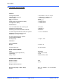
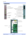
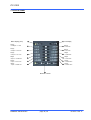
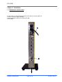
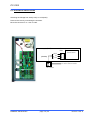
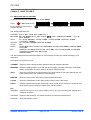
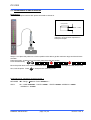
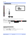
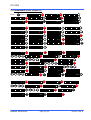
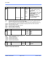
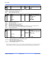
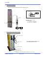
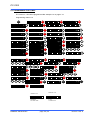
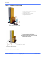
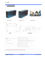
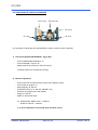
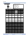
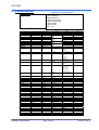
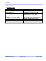
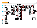
PC-2200
User’s manual
Advanced Electronic/Air Column PC-2200
BOWERS METROLOGY
page 1 /32
version 2.06 -E
PC-2200
BOWERS METROLOGY
page 2 /32
version 2.06 -E
PC-2200
CONTENTS
1.
INTRODUCTION
4
1.1
1.2
1.3
1.4
1.5
GENERAL INFORMATIONS
TECHNICAL SPECIFICATIONS
COLUMN DESCRIPTION
KEYPAD CONFIGURATION
STATUS PANEL
4
5
6
7
8
2.
INSTALLATION
9
2.1
2.2
MECANICAL INSTALLATION
ELECTRICAL INSTALLATION
9
10
3.
HOW TO USE IT
11
3.1
3.2
3.3
3.4
3.5
3.6
3.7
3.8
SWITCHING ON THE COLUMN
PROGRAMMING A SIMPLE MEASURE
PROGRAMMING A PART (EXAMPLE 1)
PROGRAMMING A DIAMETER
PROGRAMMING A PART (EXAMPLE 2)
THE CLASSIFICATION MENU
THE RS232 INTERFACE
LAYOUT OF IN/OUTPUT
11
12
13
14
15-16
17
18
19
4.
FUNCTIONS
20
4.1
4.2
4.3
4.4
4.5
THE MEASURING MODE FUNCTIONS
THE PROGRAMMING MODE FUNCTIONS
CH-BUS APPLICATIONS
CH-BUS MECANICAL INSTALLATION
PROGRAMMING THE CH-BUS
20
21-22
23
23
24
5.
PNEUMATIC INSTALLATION
25
5.1
5.2
THE A/E CONVERTER
HOW TO SETUP FOR A/E CONVERTER
26
27
6.
GENERAL INITIALIZATION
28
6.1
6.2
6.3
6.4
TABLE OF DEFAULT VALUES
APPLICATION EXAMPLES
DIAMETER/THICKNESS
BLANK SETTING SHEET
28
29
29
30
7.
GENERAL
31
7.1
7.2
TROUBLESHOOTING
MAINTENANCE
31
32
APPENDIX A. REPLACING EPROM & CPU
APPENDIX B. MENU MAP
BOWERS METROLOGY
page 3 /32
version 2.06 -E
PC-2200
CHAPTER 1. INTRODUCTION
1.1 GENERAL INFORMATIONS
-
The column PC-2200 is an instrument system that measures and displays “ID, OD, Length related
measurements such as misalignment, and others” in automotives, machines, electrical and
electronic parts, and determines whether the measured results are acceptable or not.
-
The user can identify the measurement values correctly and easily as the display is made on a
3-Color LED Bar (green, orange, red) and a DOT MATRIX LED (8 characters) mounted in the front
side.
-
The Status panel, positioned on the front bottom side, shows the current operating status in regards
to the unit system (mm/inch) and operating sets (M1, M2, M3, M4) using 12 LED’s (green).
-
The Keypad, consists of 9 membrane switches mounted below the Status panel, performs the user
program such as the system setup. The user can build the program environment that can satisfy the
user’s requirements to the maximum through the Keypad operation such as selecting the menu in
easy and free way and setting up the required variables.
-
The rear upper side is configured as the AC power switch, Fuse holder, AC power inlet and Aux.
power supply, and therefore, it can use several units of PC-2200 through connecting with only one
unit of power supply. The AC power of AC 110/230 V and 50/60 Hz is applied. You can select the
power source of 110V/230V (default : 110V) by inserting the connector on the DC power PC board
that is fixed on the upper side of the system inside.
-
With the 5 external interfaces on the rear center side, the column can be connected to another
column, PC, Printer, PLC or CNC.
-
You can use the HBT, LVDT and CAPACITIVE probes as electronic system or AIR probes through
the analog board on the rear bottom side. You should install the analog board (PCB) dedicated by
the type of probe.
-
The PC-2200 is an integrated high quality measurement system that performs various
measurements and display functions such as inter-channel operations up to 4 channels and dynamic
mode in addition to the simple displays of measurement values.
BOWERS METROLOGY
page 4 /32
version 2.06 -E
PC-2200
1.2 TECHNICAL SPECIFICATIONS
General :
Storage temperature
Operational temperature
Power supply
Max. consumption
Fuse
MTBF (Mean Time between Failure)
Average life of display
: -40°C to 60°C /- 40°F to 140°F
: 0°C to 50°C / 32°F to 122°F
: 110/230V (AC) 50/60Hz
: 40VA
: 2A delayed
: >100'000 hours
: > 50'000 hours
Performance :
Time for stabilization after switching ON
Measurement thermal drift
Measuring thermal drift between channels
: 5 minutes
: 100PPM/°C
: 30PPM/°C
PC-2200 equiped with HBT-LVDT-CAP probes
Measuring accuracy at 20°C / 68°F
Resolution = 0.1 µm / .00001’’
: ± 0.5% ± Resolution
PC-2200 equiped with Air System
in the nominal conditions
Working range
: ± 50µm / .002’’
Interfaces :
Analog OUTPUT
Range
: ± 5.0V F.S.
Full scale accuracy:
: 2% of full scale
Serial OUTPUT (RS 232)
Type
Transmission speed (Baud rate)
Word length
Parity control
: RS 232 C
: 4800, 9600, 19200
: 7 or 8
: NONE, EVEN, ODD
DC-OUT Photo couplers
Maximal Voltage
Maximal Tension
: 50V
: 60mA
Weight and Dimensions :
Dimensions (height * width * depth)
Weight
BOWERS METROLOGY
: 450 * 57 * 215mm / 17.7’’*2.16’’*8.66’’
: 4.12 kg
page 5 /32
version 2.06 -E
PC-2200
1.3 COLUMN DESCRIPTION
Rear View
Front View
ON-OFF Switch
Fuse 2A
AC power line input
Bar scale
3-color LED-bar(103ea)
Green, orange, red
Auxiliary power line (for other column)
Identification and serial numbers
RS 232 C Interface
External Control Interface
OUTPUT Interface (class)
Display (LED)
(8 chr.)
DC OUT Interface (V)
CH-BUS Interface (signal transfer)
Identification analog board
Status panel
12 (LED)
Analog board for
(HBT, LVDT,CAPACITIVE,AIR)
Keypad
9 Keys
Internal View
Top
DC Power PCB
Noise filter module
Display (PCB)
Main board PCB
Rear
Front
Analog board PCB
Bottom
BOWERS METROLOGY
page 6 /32
version 2.06 -E
PC-2200
1.4 KEYPAD CONFIGURATION
Program
Measuring mode
Access to the
programming mode
Programming mode
No function
Move upward
Measuring mode
Select M1, M2, M3, M4
Programming mode
Used to move from a specific menu
to other menu, or to increase the
values when setting the values of
variables.
Escape
Measuring mode
Initialization of dynamic mode
Programming mode
Escape to previous menu.
Move left
Measuring mode
Send data
Programming mode
Used to move from a specific menu
to other or move the selected LED
to the next left LED
Calibration
Measuring mode
Calibration functions
Programming mode
No functions
Move right
Measuring mode
No function
Programming mode
Used to move from a specific menu
to other or move the selected LED
to the next right LED
Move downward
Measuring mode
No function
Programming mode
Preset
Measuring mode
Used to set the current
measured values to 0 or
pre-selected values
(See page 20)
Programming mode
No function
BOWERS METROLOGY
page 7 /32
Enter
Measuring mode
Instrument OFF
Enter + ON = Reset
Programming mode
Used to move from a specific menu
to other menu, or to decrease the
values when setting the values of
variables.
Used to select the current
menu or to set values of
variables
version 2.06 -E
PC-2200
1.5 STATUS PANEL
Metric display (mm)
Inch display
Range
±1000µm / ±1 mm
Range
Range
±500µm / ±0.5 mm
Range
Range
±100µm / ±0.1 mm
Range
Range
Range
±50µm / ±0.050 mm
Range
± 0.001 inch
Range
± 0.0005 inch
± 0.05 inch
± 0.01 inch
± 0.005 inch
±10µm / ±0.01 mm
Range
Range
± 0.0001 inch
±5µm / ±0.005 mm
Measure number
BOWERS METROLOGY
page 8 /32
version 2.06 -E
PC-2200
Chapter 2. Installation
2.1 MECHANICAL INSTALLATION
Fix the column on the aluminum base and lock it with the 2 screws (M6 x16)
Connect the power supply cable (A) .
Connect the probe cable to the analog board (B)
Switch (ON) I.
A
B
BOWERS METROLOGY
page 9 /32
version 2.06 -E
PC-2200
2.4 ELECTRICAL INSTALLATION
Switching the Voltage from 230V(110V) to 110V(230V).
Remove the cover by unscrewing the 8 screws.
Move the connector A on 110V or 230V.
A
Power supply (PCB)
3PMale
Transformer
(Default)
220V
0V
110V
to noise filter module
2P-female
BOWERS METROLOGY
page 10 /32
version 2.06 -E
PC-2200
Chapter 3. HOW TO USE IT
3.3 SWITCHING ON THE COLUMN
To start the first time, we advise to make a general RESET .
Press
Enter
+ ON simultaneously, ▓ B O W E R S ▓
Do not release your pressure on
program will start.
Enter
R ES E T . . .
-
1 . 0 4 0 0
before the message RESET appears on the display, then a test
The default parameters are :
CHANNEL : Source : Ext. - CH-A Ratio :1.000 Direc. +
MEASURE : M1 – Bar :Bottom B.fact. 1.00 – Range : ± 0.05” Sens : 1.000 Resol.:0.00005” – Func: A –
Mode: STATIC
SPEC.
: M1 – NOMI. 000.0000 - -TOLER –0.0500 - +TOLER +0.0500 –APPROCH –0.0500
+ APPROCH : +0.0500
MASTER : M1 - -MASTER +0.00000 +MASTER +0.00000
CLASS
: OFF
RS232
: SPEED 9600, DATA 8, PARITY N, TERM CRLF, RTS ON, PRINT BRIEF, RSMODE PRINT
ID NO. 000
ETC
: GENERAL UNIT INCH, DISPLAY mm, INPUT HBT, P/W PROGRAM 0000, CALIBR OFF
AVERAGE BAR 005, DIGIT 005, A/D 20
VERSION V2.xx
The above parameters are the default values, so it is necessary to modify the values according to your
application.
Description of functions per menu
CHANNEL : Select the source and the probes used with ratio and measuring direction.
MEASURE : Select the starting position of the bar, Bar factor, Range of the Bar, Resolution of the digital
display, Combination of probes, Static or Dynamic measuring mode.
SPEC.
: Store the nominal size, the upper tolerance, the lower tolerance, the upper warning limit, the
lower warning limit of the component to be measured.
MASTER
: Store the lower master value and the upper master value used.
CLASS
: Active the classification mode, class number, starting value, class range.
RS232
: Select the transmission speed, word length, parity control, end of characters, request to send
signal, printing mode, simplex or duplex mode, identity number.
ETC
GENERAL : Select the unit (mm or inch), type of display (mm or um), type of probes used, program and
calibration password.
AVERAGE : Select the bar sensitivity , the display sensitivity, the analog board sensitivity.
VERSION : Show the software version.
BOWERS METROLOGY
page 11 /32
version 2.06 -E
PC-2200
3.2 PROGRAMMING A SIMPLE MEASURE
Example N°1
Measure a component with a HBT probe connected to channel A.
Component
20.000mm ± 0.005
USING a HBT probe, we do not use the
calibration, this mode will be explained in a
subsequent chapter.
Master
20.0000mm
Step n°1 is to place the probe into a correct position to be able to get the maximum range and the minimum
deviation.
Place the master 20.0000 mm on the stand, place the probe into position.
Press simultaneously
Enter
S
Enter
1 . 0 5 0 0
C H - A
A D J U S T
Move the probe down to the electro-mechanical zero, zero, lock the probe . Press
Esc
0 . 0 0 1 0 , then approximately stop around
to escape to the measuring mode.
Parameters to be changed for example number 1
MEASURE : M1 –Range : ± 0.01mm Resol.:0.0002mm –
SPEC.
: M1 – NOMI. 020.0000 - -TOLER –0.0050 - +TOLER +0.0050 –APPROCH –0.0040
+ APPROCH : +0.0040
BOWERS METROLOGY
page 12 /32
version 2.06 -E
PC-2200
3.3 PROGRAMMING A PART (EXAMPLE 1)
Press
Prog
(2 sec.)
P / W
0 0 0 0
Enter
M 1
Enter
S E L E CT
B AR
R ANG E
Enter
±
1 . 0
±
0 . 5
±
0 . 0 1
±
0 . 0 0 5
±
0 . 0 5
S EN S .
R ESO L .
Enter
Esc
0 . 0 0 0 2
Enter
R ESO L .
S PE C .
Enter
M 1
S
-
M
0 . 8 0 0 0
+ TO L ER
S
M
Enter
+
+ TO L ER
S
Esc
0 . 0 0 4 0
M
Enter
0 2 0 . 0 0 0 0
Enter
0 . 8 0 0 0
- AP P RO
Enter
+
S A V E ?
S
Enter
Enter
Esc
N OM I .
Enter
Esc
R ANG E
MEA S URE
0 0 0 . 0 0 0 0
- TO L ER
Enter
0 . 0 0 5 0
0 . 8 0 0 0
M 1
Enter
- TO L ER
+
M
-
0 . 1
0 . 0 0 0 5
M 1
+ AP P RO
Enter
±
0 . 0 0 1
0 . 0 0 5 0
Enter
B . F A CT
N OM I .
- AP P RO
0 . 0 0 4 0
MEA S URE
C HAN NE L
S
Enter
Esc
Enter
M
+
0 . 8 0 0 0
S PEC .
Enter
Place the master 20.0000mm in contact with the probe, then press
Preset
P RE S ET
Enter
Upper tolerance
Upper approach limit
The approach limit should be within the tolerance.
Nominal value
Lower approach limit
Lower tolerance
BOWERS METROLOGY
page 13 /32
version 2.06 -E
PC-2200
3.4 PROGRAMMING A DIAMETER
Measurement of a diameter with a HBT probe connected to channel A.
Component
15.000 mm ± 0.002
Min master
14.9988mm
Max. master.
15.0026mm
Step n°1 is to place the probe into a location to be able to get the maximum range and the minimum
deviation.
Place the measuring head of 15.0000 mm in the master,
Press simultaneously
Enter
S
Enter
1 . 0 5 0 0
C H - A
A D J U S T
Move the probe down to the electro-mechanical zero. zero, lock the probe . Press
Esc
0 . 0 0 1 0 , then approximately stop around
to escape to the measuring mode.
Parameters to be changed for example number 2
CHANNEL : Direc. MEASURE : M1 –Range : ± 0.005 mm Resol.: 0.0001mm –
SPEC.
MASTER
: M1 – NOMI. 015.0000 - -TOLER –0.0020 - +TOLER +0.0020 –APPROCH –0.0016
+ APPROCH : +0.0016
: M1 - -Master : 14.9988mm - +Master : 15.0026mm
BOWERS METROLOGY
page 14 /32
version 2.06 -E
PC-2200
3.5 PROGRAMMING A PART (EXAMPLE 2)
Press
Prog
(2 sec.) P / W
0 0 0 0
C HA N NE L
Enter
S OUR CE
Enter
D I R E C
+
Enter
R A T I O
Enter
D I R E C
Esc
Enter
M 1
Enter
S E L E CT
B AR
B . F A CT
R ANG E
Enter
±
1 . 0
±
0 . 5
±
±
±
0 . 0 1
±
0 . 0 0 5
C H - A
-
MEA S URE
0 . 1
Enter
C H - A
0 . 0 5
C HAN NE L
Esc
R ANG E
S EN S .
R ESO L .
Enter
0 . 0 0 1
0 . 0 0 0 5
0 . 0 0 0 2
0 . 0 0 0 1
Enter
R ESO L .
M 1
Esc
S PEC .
S
-
M
0 . 8 0 0 0
+ TO L ER
Enter
S
0 . 0 0 1 6
M
MAS T ER
S
M
M 1
S
M
Enter
+
Enter
Enter
0 . 8 0 0 0
- AP P RO
Enter
Enter
0 1 5 . 0 0 0 0
S
M 1
Esc
BOWERS METROLOGY
Enter
0 . 0 0 2 0
S
M
Enter
-
M
MAS T ER
Esc
Enter
Enter
Enter
Enter
0 1 5 . 0 0 2 6
S
Enter
Esc
- MA S T ER
Enter
S A V E ?
page 15 /32
0 . 0 0 2 0
0 . 8 0 0 0
M 1
Enter
- TO L ER
+
- MA S T ER
Esc
0 0 0 . 0 0 0 0
- TO L ER
+ AP P RO
M 1
0 1 4 . 9 9 8 8
N OM I .
N OM I .
- AP P RO
0 . 0 0 1 6
+
Esc
MEA S URE
0 1 5 . 0 0 0 0
+ TO L ER
Enter
Enter
Enter
M
+
0 . 8 0 0 0
S PE C .
0 1 5 . 0 0 0 0
+ MA S T ER
+ MA S T ER
Enter
Esc
Enter
version 2.06 -E
PC-2200
The Calibration
Example N°2
The parameters are now stored. The automatic calibration can be started.
Min. master
14.9988mm
Cal
C A L . . M1
Enter
Max.master
15.0026mm
C A L .
place the measuring head in the lower master.
place the measuring head in the upper master.
C A L .
Enter
Enter
0 . 9 8 1
The sensitivity is calculated automatically.
If the message M I N
then the calculated value.
Cal
C A L . . M1
V A L U E
Enter
O V E R appears, that means that the value between the two masters is bigger
MODU L E
Enter
M 1
Enter
C A L %
0 0 0 %
NONE : All sensitivity values are allowed.
000% : The sensitivity value will not be accepted if the calculated value during the calibration is different
from the stored value.
XXX% : The sensitivity value will not be accepted if the calculated value during the calibration is different
from XXX% of the stored value.
After the calibration the measurement can be started.
BOWERS METROLOGY
page 16 /32
version 2.06 -E
PC-2200
3.6 THE CLASSIFICATION MENU
CLASS
The class menu is used separately.
Example : Pin dia. 10mm - 0 +0.100mm to be classified by steps of 0.005mm , in 20 classes, starting from
10.0000 mm.
Prog
(2 sec) P / W
Enter
S PE C .
C L A S S
MAS T ER
O F F
0 1 0
S T A R T
S
Enter
S T A R T
0 0 0 . 0 0 5 0
ON
M
Enter
OK
MEA S URE
C HA N NE L
Enter
S E L E CT
0 2 0
M
0 0 0 . 0 0 0 0
S
S T E P
Enter
S T E P
Esc
C
Enter
Enter
M
S E L E CT
Enter
N UMB ER
Enter
N UMB ER
0 1 0 . 0 0 0 0
0 0 0 . 0 1 0 0
C L A S S
measure the first pin
S
Esc
Enter
M
S AV E ?
C
Enter
5
The first pin will be classified into class 5, and the printed value will be between 10.025 and 10.030 mm
To escape from the Class menu, SELECT. OFF
BOWERS METROLOGY
page 17 /32
version 2.06 -E
PC-2200
3.2 THE RS232 INTERFACE
The RS 232 Interface allows to send the data to a printer, as well to a PC, also allows to modify the stored
parameters in the column with the help of the communicator software.
How to connect a PC-2200 to a serial printer.
The most important to connect a column to a printer or a computer is the
adjustment of parameters.
The first values to be known are the serial printer parameters.
e.g. : 4800 bauds, 7 bits, parity even.
adjustment
How to setup the column ?
Prog
(2 sec.)
P / W
0 0 0 0
MAS T ER
S PE C .
C LA S S
9 60 0
S PE E D
Enter
D AT A
Enter
P AR I T Y
Enter
N ON E
M
T ERM
Enter
C R
M
R TS
Enter
P R I N T
Enter
B R I E F
R SMO D E
Enter
P R I N T
I D
N O .
S AV E ?
Press
S
ID NO :000
MEA S URE
C HA N NE L
Enter
M
8
R S2 3 2
4 80 0
Enter
S PE E D
Enter
D AT A
E VE N
Enter
P AR I T Y
C RL F
Enter
T ERM
Enter
R TS
Enter
P R I N T
Esc
R S2 3 2
7
M
ON
O F F
F U L L
Enter
Enter
0 0 0
Enter
2 . 0 0 0 0
Enter
R SMO D E
Enter
I D
N O .
Esc
S END . . .
M1 :+ 2.000mm
OK
ID NO :000
BOWERS METROLOGY
page 18 /32
M1 :+ 2.000mm
OK
version 2.06 -E
PC-2200
3.1 LAYOUT OF IN/OUTPUT
6
7
RS-232 C
8
9
Pin#
1
2
3
4
5
6
7
8
9
Functions
* (not connected)
Rxd
Txd
Vcc
Gnd
* (not connected)
Rts
Cts
Gnd
1
2
3
4
5
6
7
EXT.CON
8
9
Pin#
1
2
3
4
5
6
7
8
9
Functions
RS 232 sortie (0.5 sec.)
Current value display
Dynamic/Static
M1->M2->M3->M4
Hold measure
* (not connected)
* (not connected)
* (not connected)
Gnd
1
2
3
4
5
6
7 OUTPUT
8
9
Pin#
Functions
1
2
3
4
5
1
2
3
4
5
6
7 DC OUT
8
9
1
2
3
4
5
6
7 CH-BUS
8
9
1
2
3
4
5
6
7
8
9
O.K (Green)
* (not connected)
Approch + (Orange)
+N.G (Red)
* (not connected)
Approch – (Orange)
-N.G (Red)
Drive Voltage
Gnd
Pin#
1
2
3
4
5
6
7
8
9
Functions
D/A sortie
* (not connected)
* (not connected)
* (not connected)
* (not connected)
* (not connected)
* (not connected)
* (not connected)
Gnd
Pin#
1
2
3
4
5
6
7
8
9
Functions
Ex-A
Ex-B
Ex-C
Ex-D
Gnd
* (not connected)
* (not connected)
* (not connected)
Gnd
(Connection of a serial printer or a PC)
In the case of RS232-RS mode is set as “PRINT”, the display value is printed via the RS232 by
connecting the pins #1,9 of external control..
If the RS 232-RS mode is set as « HOST », the communication becomes (duplex) and allows to
use the communicator software.
The external control functions can be activated by connecting the pins #1 to 5 to the pin
#9(GND) according to the required function.
The following functions can be activated by connecting the pin #9 to pin # (foot pedal, box)
#1)Print the display value. #2) Change dynamic mode to static mode
#3) Reset the dynamic mode (min., max.) #4) Move the measurement mode (M1) to M2,……
M2,M3,M4 should be active. (ON)
#5) Freeze the displayed value.
Active the preset mode by connecting the pin #3 and #5 simultaneously
Class Mode
(Binary)
Bit 0
Bit 1
Bit 2
Bit 3
Bit 4
Bit 5
Bit 6
Active the contact with GND pin#9 when the value of the bar is positioned in the
corresponding range pins #1, 3, 4, 6, 7) .
This application shows if the product is acceptable or not with an external unit
such as lamps, relays, by powering the pins #8,9.
If the Class mode is turned on, the judgement mode(OK, +/-NG, etc.) is
automatically turned off and the data is output with BCD code through the same
port(each pin).(Refer to the chapter 3.6 for setting up.)
Analog output of the display (Signal Voltage (pin #1 and #9).
The voltage range is :
Approx. ±4.3V with ±1 mm, or ±0.05 inch
This function is used when the signal of a probe should be shifted to a second column.
Application : Example : Display a maximum value on 1 column and a minimum value to the other
column with only one probe..
The analog board of the column which is receiving the data should be disconnected,.
Circuit connection diagram (OUTPUT)
CH-Bus diagram
E
#4
#3
#1
#6
#7
#9
Red (bigger value than TOLER+)
Probe
input
Analog board PCB
A B
C
D
Orange (Value between APPRO+ and TOLER+)
EX-A (pin #1)
EX-B (pin #2)
EX-C (pin #3)
EX-D (pin #4)
Green (Value between APPRO- and APPRO+)
Orange (Value between APPRO- and TOLER-)
Red (smaller value than TOLER-)
GND
A/E-Converter
E=External voltage
Display controller
BOWERS METROLOGY
page 19 /32
version 2.06 -E
PC-2200
Chapter 4. Functions
Definition of keypad functions per menu
4.1 THE MEASURING MODE FUNCTIONS
Functions
Functions
Access to programming mode
Prog
“M” Change the measure number (M1-M2)
only if M2,M3,M4 (ON)
M
M1-M2-M3-M4
Esc
“S” send the displayed value to RS232
S
No function in measuring mode
No function in measuring mode
Enter
Preset
Cal
Preset
Value
M1
00.0000
Calibration
Module M1, M2, M3,M4
CAL%
Simultaneously when switching (ON)
RESET
Access to preset mode
Value = Norm. value + Meas. range.
PRESET
Maximum
+/- 0.05”
Cal. Min__ and Max
Cal. by measure M1, M2, M3, M4
NONE, Value XXX%
4.2 THE PROGRAMMING MODE FUNCTIONS
Prog
Menu
CHANNEL
Sub-menu
SOURCE
CH-A
CH-B
CH-C
CH-D
Functions
EXT.
CH-BUS
RATIO
RATIO
RATIO
RATIO
Functions
Functions
Functions
1.000
1.000
1.000
1.000
DIRECT
DIRECT
DIRECT
DIRECT
+/+/+/+/-
SOURCE : EXT. Select the source of the probe on the analog board on this column.
CH-BUS. Select the source of the probe from another column thru the CH-BUS.
CH-A
: Select the ratio value and measuring direction for the channel A.
CH-B
: Select the ratio value and measuring direction for the channel B.
CH-C
: Select the ratio value and measuring direction for the channel C.
CH-D
: Select the ratio value and measuring direction for the channel D.
BOWERS METROLOGY
page 20 /32
version 2.06 -E
PC-2200
Prog
Menu
MEASURE
Sub-menu
M1
Functions
ON
Functions
BAR
B. FACT
RANGE
SENS.
RESOL.
FUNC
MODE
M2, M3, M4
ON/OFF
……….
Functions
BOTTOM,CENTER,-10->0
1.00
± 0.05, ±0.01, ±0.005, ± 0.001, ±
0.0005, ±0.0001
1.000
0.005,0.001,0.0005,0.0001,0.00005,
0.00002, 0.00001”
A,B,C,D,A+B,A-B,C+D,(A+B)-C,
(A+B+C)/3,(A+B+C+D)/4,
(A+B)-(C+D)
STATIC,MAXIMUM,MINIMUM,
(M+m)/2,(M-m)/2,M-m.
M1,M… : Select the characteristics of the measuring result M1, it is possible to store 4 different measuring
results (M1, M2, M3, M4). M2, M3, M4 should be (ON)
BAR
: Select the starting position of the LED-bar, (BOTTOM) start from bottom, (CENTER) start from
center, (-10->0) start from an excentred position in case of being out of range with the LED – bar.
B.FACT : Bar multiplication factor, giving the possibility of adjusting several column at the same level.
RANGE : Select the measuring range.
SENS : Calculated sensitivity value after calibration.
RESOL : Select the measuring resolution..
FUNC : Select the setting of measurement.
MODE : Select the dynamic or static mode
Prog
Menu
SPEC.
Sub-menu
M1
Functions
M2
M1,M..
NOMI.
-TOLER
+TOLER
-APPRO
+APPRO
Prog
Functions
NOMI.
-TOLER
+TOLER
-APPRO
+APPRO
……
Functions
0.00000”
-0.05”
+0.05”
-0.05”
+0.05”
……
Functions
Functions
+0.00000”
+0.00000”
………
: Store in measurement number 1, 2, 3, 4.
: Store the nominal size
: Store the lower tolerance.
: Store the upper tolerance.
: Store the lower warning limit.
: Store the upper warning limit.
Menu
MASTER
Sub-menu
M1
Functions
-MASTER
+MASTER
M2
…..
M1,M… : Store in measurement number 1, 2, 3, 4.
-MASTER : Store the lower master value.
+MASTER : Store the upper master value.
BOWERS METROLOGY
page 21 /32
version 2.06 -E
PC-2200
Prog
Menu
CLASS
Sub-menu
Select
Functions
ON/OFF
Functions
NUMBER
START
STEP
Functions
000
+0.0000”
0.0000
Functions
Functions
4800,9600,19200 BAUD RATE
7,8 Bits
NONE, ODD,EVEN
CRLF / CR
ON / OFF
BRIEF / FULL
PRINT /HOST
000
CLASS : Switch ON or OFF the class menu.
NUMBER : Store the number of classes to be used.
START : Store the starting nominal value
STEP
: Store the step value of the class.
Prog
Menu
RS232
SPEED
DATA
PARITY
TERM
RTS
PRINT
RS232
ID NO
Prog
Sub-menu
SPEED
DATA
PARITY
TERM
RTS
PRINT
RSMODE
ID NO.
Functions
: Select the transmission speed .
: Select the word length.
: Select the parity control : none, even, odd
: Select the end characters : CR, CRLF
: (Request to Send) request to send a signal
: Select the printing mode, (BRIEF) send the minimum data, (FULL) send a complete protocol.
: Select the RS232 Interface in mode PRINT(Simplex) or HOST (Duplex)
: Store an identity number.
Menu
ETC
Sub-menu
GENERAL
Functions
UNIT
DISPLAY
INPUT
P/W
AVERAGE
BAR
DIGIT
A/D
VERSION
Functions
Functions
METRIC, INCH
mm or um
HBT,LVDT,CAP_1,CAP_5,AIR
PROGRAM 0000
CALIBR.
ON/OFF 0000
005
005
20
v 2.xx BMI
GENERAL : Select the measuring unit, select the display (mm or um), select the analog board used, store a
PROGRAM password and a CALIBRATION password.
AVERAGE : BAR, Store a filter for the bar.
DIGIT, Store a filter for the digital display.
A/D, Store a filter for analog/digital converter.
VERSION : Show the software version.
※ When changing the unit(metric to inch or inch to metric) it will be automatically out of the program without
saving or confirming. The user should check the specification input after going into the program again.
BOWERS METROLOGY
page 22 /32
version 2.06 -E
PC-2200
4.3 CH-BUS APPLICATIONS
The CH-BUS channel transfers a data signal to another column.
Application.
Component
0.002
15.000mm ± 0.007
1 probe
We need to see 2 values
simultaneously.
1. Diameter 15.0000mm
2. max T.I.R 0.002mm
Dia.
Max-min
Min.master.
14.9988mm
Max.master
15.0026mm
4.4 CH-BUS MECHANICAL INSTALLATION
Column n°2
Column n°1
Power supply cable
Cable PC-2302
The receptive column should have
the analog board removed.
Cable PC-2352
Probe cable
Analog board
Column without analog board (Blank back cover PC-2009)
BOWERS METROLOGY
page 23 /32
version 2.06 -E
PC-2200
4.5 PROGRAMMING THE CH-BUS
The column n°1 should be programmed like example n°2 on page n°15
Programming column n°2
P / W
Prog
0 0 0 0
C H - B US
E X T .
C HAN NE L
Enter
Enter
S OUR CE
Enter
S OUR CE
Enter
C HA N NE L
Esc
M 1
Enter
S E L E CT
B AR
B . F A CT
R ANG E
Enter
±
1 . 0
±
0 . 5
±
±
±
0 . 0 1
±
0 . 0 0 5
MEA S URE
Enter
0 . 1
0 . 0 5
R ANG E
S EN S .
R ESO L .
Enter
0 . 0 0 1
0 . 0 0 0 5
0 . 0 0 0 2
0 . 0 0 0 1
Enter
R ESO L .
F UNC .
MOD E
Enter
MOD E
Esc
M - m
S PE C .
S
-
M
0 . 0 0 0 0
+ TO L ER
Enter
Enter
S
0 . 0 0 1 6
M
S AV E ?
Enter
0 0 0 . 0 0 0 0
S
M
Enter
+
+ TO L ER
-
M 1
Enter
0 . 0 0 0 0
- AP P RO
Enter
+
Enter
M 1
N OM I .
Enter
Esc
Enter
0 0 0 . 0 0 0 0
Enter
0 . 8 0 0 0
M 1
0 . 0 0 2 0
S
Enter
Esc
Enter
M
+
0 . 8 0 0 0
S PEC .
Esc
0 . 0 0 0 0
Column n°2
Column n°1
15 . 0 0 0 0
Diameter
15.0000 mm
BOWERS METROLOGY
+
+ AP P RO
Enter
MEA S URE
- TO L ER
Enter
M
-
Esc
- TO L ER
0 . 0 0 0 0
- AP P RO
0 . 0 0 1 6
S T A T I C
N OM I .
S
Enter
0 . 0 0 0 0
T.I.R
0.0020 mm
page 24 /32
version 2.06 -E
PC-2200
Chapter 5. PNEUMATIC INSTALLATION
1. Fix the column and the converter on
the aluminum base.
2. Fix the hose of the air probe
to nipple of converter.
Hose nipple for the air probe
3. Connect the cable PC-2332 between the
converter and the analog board.
4. Connect the air supply hose to the hose
nipple on the converter.
Air supply hose nipple
Connection cable PC-2332.
Not less than 3 bar of air should be supplied.
BOWERS METROLOGY
page 25 /32
version 2.06 -E
PC-2200
5.1 THE A/E CONVERTER
< Front View>
<Rear View>
(View)
<Internal View>
(Diagram)
The programming procedure is similar to an electronic probe.
BOWERS METROLOGY
page 26 /32
version 2.06 -E
PC-2200
5.2 HOW TO SETUP FOR A/E CONVERTER
A. BALANCE
B. PRESSURE
E. SIGNAL
C. GAGE
D. AIR IN
It is necessary to adjust the A/E CONVERTER in order to use this Column optimally.
1) Pressure Adjustment(STANDARD : 2 ± 0.1bar)
-
Connect PRESSURE GAUGE to “C”.
Connect AIR(Min. 3 bar) to “D”.
Adjust pressure by turning “B” with screw driver.
♦ Default pressure is 2 bar(Factory setting).
2) Balance adjustment
-
Connect the A/E converter and the Column with cable(PC-2332).
Connect the air gauge to “C”.
Stop supplying “D” with air.
Preset the Column to “0” with the “PRESET” key.
Place the air gauge into the Min. Master.
Supply “D” with air.
Adjust “A” with screw driver.
예) Example) Min. Master value : -0.020mm
DISPLAY VALUE : -0.020mm
♦ In case of unbalance, measuring range could be narrow.
BOWERS METROLOGY
page 27 /32
version 2.06 -E
PC-2200
Chapter 6. GENERAL INITIALIZATION
(1) Function: Initialize all stored data to the default values. CAUTION : All your stored data will be
erased. Press
Enter
+ ON
6.1 TABLE OF DEFAULT VALUES
Menu
CHANNEL
Sub-menu
SOURCE
Selection
EXT.
CH-BUS
CH-A
CH-B
CH-C
CH-D
MEASURE
M1
SELECT
Functions
Choice
Default value
EXT.
RATIO
DIREC.
RATIO
DIREC.
RATIO
DIREC.
RATIO
0 - 5.000
+/0 - 5.000
+/0 - 5.000
+/0 - 5.000
1.000
+
1.000
+
1.000
+
1.000
DIREC.
ON
BAR
+/-
+
ON
BOTTOM
B.FACT
RANGE
BOTTOM
CENTER
-10->0
-5.00 / +5.00
1.00
± 0.05”
± 0.01”
± 0.005”
± 0.001”
± 0.0005”
± 0.0001”
± 0.01 ~ 5.000
± 0.05”
RESOL.
0.005, 0.001, 0.0005,
0.0001, 0.00005,
0.00002, 0.00001
0.00005”
FUNC
A, B, C, D, A+B, A-B,
C+D, (A+B)-C,
(A+B+C)/3,
(A+B+C+D)/4
(A+B)-(C+D)
STATIC, MAXIMUM,
MINIMUM,(M+m)/2,
(M-m)/2, M-m
A
SENS.
MODE
1.000
STATIC
SPEC.
M1
NOMI.
-TOLER.
+TOLER
-APPRO
+APPRO
000.0000
-0.0000
+0.0000
-0.0000
+0.0000
0.00000
-0.05
+0.05
-0.05
+0.05
MASTER
M1
+0.0000
+0.0000
CLASS
SELECT
-MASTER
+MASTER
OFF / ON
NUMBER
START
STEP
SPEED
1 - 100
+0.0000
0.0000
19200, 9600, 4800
+0.0000
+0.0000
OFF
010
+0.00000
0.001
9600
DATA
PARITY
TERM
RTS
PRINT
RSMODE
7, 8
None,even,Odd
CR,CRLF
ON / OFF
BRIEF, FULL
PRINT,HOST
8
None
CRLF
ON
BRIEF
PRINT
ID NO.
UNIT
DISPLAY
INPUT
P/W
BAR
000
METRIC,INCH
Mm, um
HBT,LVDT,CAP,AIR
PROGRAM
CALIBR.
000
000
INCH
mm
HBT
0000
OFF
005
DIGIT
A/D
000
00
RS232
ETC
GENERAL
AVERAGE
VERSION
BOWERS METROLOGY
page 28 /32
ON/OFF
005
20
V2.xx
version 2.06 -E
PC-2200
6.2 APPLICATION EXAMPLES
6.3 DIAMETER/THICKNESS
<Specification of the measure>
External diameter : 10.000 mm
Lower tolerance : - 20µm
Upper tolerance: +20µm
Lower warning limit: - 15µm
Upper warning limit: +15µm
Lower master : 9.980 mm
Upper master : 10.020 mm
Unit : mm
A
B
<Initialisation>
Menu
CHANNEL
Sub-menu
SOURCE
Selection
EXT.
CH-BUS
CH-A
CH-B
CH-C
CH-D
MEASURE
M1
SELECT
Function
RATIO
DIREC.
RATIO
DIREC.
0 - 5.000
+/0 - 5.000
+/-
1.000
+
1.000
+
RATIO
DIREC.
RATIO
DIREC.
0 - 5.000
+/0 - 5.000
+/-
1.000
+
1.000
+
ON
BAR
SENS.
RESOL.
FUNC
MODE
M1
MASTER
M1
CLASS
SELECT
RS232
ETC
GENERAL
AVERAGE
ON
BOTTOM
CENTER
-10->0
CENTER
-5.00 / +5.00
1.00
± 1.0mm
± 0.5mm
± 0.1mm
± 0.05mm
± 0.01mm
± 0.005mm
± 0.01 ~ 5.000
± 0.05mm
0.01, 0.005, 0.001,
0.0005, 0.0002,
0.0001
A, B, C, D, A+B, A-B,
C+D, (A+B)-C,
(A+B+C)/3,
(A+B+C+D)/4
(A+B)-(C+D)
STATIC, MAXIMUM,
MINIMUM,(M+m)/2,
(M-m)/2, M-m
1.000
0.001
A+B
STATIC
NOMI.
-TOLER.
+TOLER
000.0000
-0.8000
+0.0000
010.000
-0.0200
+0.0200
-APPRO
+APPRO
-MASTER
+MASTER
OFF / ON
NUMBER
START
-0.0000
+0.0000
+00.0000
+00.0000
1 - 100
+00.0000
-0.0150
+0.0150
+9.9800
+10.0200
OFF
010
+00.0000
STEP
SPEED
DATA
PARITY
TERM
RTS
0.0000
19200, 9600, 4800
7, 8
None,even,Odd
CR,CRLF
ON / OFF
0.0100
9600
8
None
CRLF
ON
PRINT
RSMODE
ID NO.
UNIT
DISPLAY
INPUT
P/W
BRIEF, FULL
PRINT,HOST
000
METRIC,INCH
mm, um
HBT,LVDT,CAP,AIR
PROGRAM
BRIEF
PRINT
000
METRIC
mm
HBT
0000
BAR
DIGIT
A/D
CALIBR.
000
000
00
VERSION
BOWERS METROLOGY
Values
EXT.
B.FACT
RANGE
SPEC.
Choice
page 29 /32
ON/OFF
OFF
003
003
10
V2.00
version 2.06 -E
PC-2200
6.4 BLANK SETTING SHEET
<Specification of the measure>
Nominal size :
Lower tolerance:
Upper tolerance:
Lower warning limit:
Upper warning limit:
Lower master :
Upper master:
Unit : mm
<Initialisation>
Menu
CHANNEL
Sub-menu
SOURCE
Selection
EXT.
CH-BUS
CH-A
CH-B
CH-C
CH-D
MEASURE
M1
SELECT
Function
RATIO
DIREC.
RATIO
DIREC.
0 - 5.000
+/0 - 5.000
+/-
RATIO
DIREC.
RATIO
DIREC.
ON
BAR
0 - 5.000
+/0 - 5.000
+/-
B.FACT
RANGE
SENS.
RESOL.
FUNC
MODE
SPEC.
M1
MASTER
M1
CLASS
SELECT
RS232
ETC
GENERAL
AVERAGE
NOMI.
-TOLER.
+TOLER
000.0000
-0.8000
+0.0000
-APPRO
+APPRO
-MASTER
+MASTER
OFF / ON
NUMBER
-0.0000
+0.0000
+00.0000
+00.0000
1 - 100
START
STEP
SPEED
DATA
PARITY
TERM
RTS
+00.0000
0.0000
19200, 9600, 4800
7, 8
None,even,Odd
CR,CRLF
ON / OFF
PRINT
RSMODE
ID NO.
UNIT
DISPLAY
INPUT
BRIEF, FULL
PRINT,HOST
000
METRIC,INCH
mm, um
HBT,LVDT,CAP,AIR
P/W
PROGRAM
CALIBR.
000
000
00
BAR
DIGIT
A/D
Choice
Values
BOTTOM
CENTER
-10->0
-5.00 / +5.00
± 1.0mm
± 0.5mm
± 0.1mm
± 0.05mm
± 0.01mm
± 0.005mm
± 0.01 ~ 5.000
0.01, 0.005, 0.001,
0.0005, 0.0002,
0.0001
A, B, C, D, A+B, A-B,
C+D, (A+B)-C,
(A+B+C)/3,
(A+B+C+D)/4
(A+B)-(C+D)
STATIC, MAXIMUM,
MINIMUM,(M+m)/2,
(M-m)/2, M-m
ON/OFF
VERSION
BOWERS METROLOGY
page 30 /32
version 2.06 -E
PC-2200
Chapter 7. General
7.1 TROUBLE SHOOTING
Default
The digital display & LED display are off.
The digital display is off.
The digital display & LED display are not moving.
The function M2, M3, M4 do not work
The calibration is refused “OVER MINIMUM”
BOWERS METROLOGY
Actions
Check the power(AC 110)
Check the fuse(2A)
Check the power switch(ON) position
Reset the column.(“Enter” key + Power ON)
Check the probe position
Check the connection of probe & column.
Check the connection of main board & analog board.
The functions M2, M3, M4 must be turned ON at
MEASURE menu.
One or a few data are not compatible between the
specification values and the master values.
page 31 /32
version 2.06 -E
PC-2200
7.2 MAINTENANCE
Please do not forget that this measuring instrument must be treated with care.
Take notice that this “User’s manual” is in relation with the software version V.2.00.
Please do not hesitate to contact us if you need further assistance.
BOWERS METROLOGY
page 32 /32
version 2.06 -E
Menu Map for PC2200(V2.xx)
BN20914
YES(ENTER)
Prog
P/W
> 2 sec
CHANNEL
MEASURE
SPEC
EXT.
M1
SELECT
CH-BUS
PRESET
VALUE
CH-A
M1
ⓐ
M2
ⓐ
M3
ⓐ
M4
ⓐ
ON
M1
CLASS
RS232C
RATIO=
0 ~ 5.000
DIREC.=
+
BAR
RATIO=
DIREC.=
CAL..M(X)
MOUDLE
CH-EA
(xxxx)
RATIO=
B.FACT
0.1 ~ 5.00
RANGE
ⓑ
SENS.
±0.010~5.000
RESOL
ⓒ
FUNC
A
0 ~ 5.000
M1
CAL ̄
M2
xxxx
M3
xxxx
M4
NONE
+
M2
VALUE
000%
0 ~ 5.000
+
C
-
D
"
CH-ED
- MASTER
ⓓ
SELECT
OFF
SPEED
ETC.
+ TOLER
ⓕ
+ MASTER
ⓓ
M2
- MASTER
ⓓ
NOMI.
ⓕ
ⓕ
+ MASTER
M3
ⓔ
- MASTER
+ MASTER
- TOLER
ⓕ
+ TOLER
ⓕ
M4
4800
GENERAL
UNIT
9600
INCH
CLASS_No
4~100
START
ⓖ
STEP
ⓗ
DISPLAY
DATA
INPUT
PARITY
ⓓ
+ MASTER
ⓓ
HBT
LVDT
NONE
ODD
CAP_1
EVEN
CAP_5
ⓓ
ⓓ
㎜
㎛
7
8
ⓓ
- MASTER
METRIC
19200
AIR
TERM
CRLF
CRLF
RTS
P/W
ON
PROGRAM
****
CAL.P/W
OFF
OFF
B
DIREC.=
ⓕ
+APPRO
"
CAL_
- TOLER
-APPRO
-
CAL%
M1
-10 → 0
OR
P/W
ⓔ
BOTTOM
CENTER
"
CH-D
NOMI.
ON
-
>0.5 sec
MASTER
OFF
"
>0.5 sec
Cal
NO(ESC)
(xxxx)
SOURCE
Preset
SAVE?
-APPRO
ⓕ
+APPRO
ⓕ
NOMI.
ⓔ
ON
AVERAGE
PRINT
BAR
2~50
FULL
DIGIT
2~50
PRINT
A/D
2~20
BRIEF
A+B
RATIO=
0 ~ 5.000
A–B
M3
RSMODE
HOST
C+D
DIREC.=
+
(A+B)-C
-
- TOLER
ⓕ
(A+B+C)/3
VERSION
ID_NO
(A+B+C+D)/4
+ TOLER
ⓕ
-APPRO
ⓕ
+APPRO
ⓕ
NOMI.
ⓔ
- TOLER
ⓕ
V 2.xx
0~255
(A+B)-(C+D)
+
ADJUST
>0.5 sec
MODE
CH-A
xxxx
STATIC
MAXIMUM
"
MINIMUM
"
(M+m)/2
CH-D
xxxx
CH-EA
xxxx
M-m
"
M4
(M-m)/2
M2
Same as M1 map
+ TOLER
ⓕ
Enter Key
M3
Same as M1 map
-APPRO
ⓕ
Left/Right Key
M4
Same as M1 map
+APPRO
ⓕ
Up/Down Key
"
CH-ED
Enter
+ Power S/W
xxxx
Initialization of setup data
Retun to upper menu in setup mode
Esc
Reset in dynamic mode
S
M
Data sending(Digital display Value)
M1~M2~M3~M4 Transfer (Toggle key)
****