1
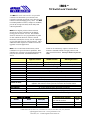
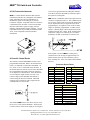
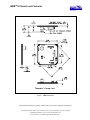
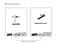
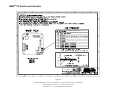
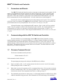
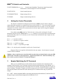
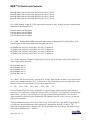
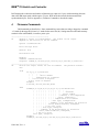
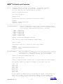
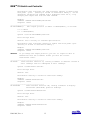
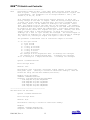
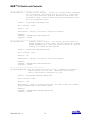
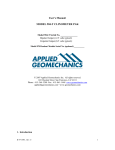
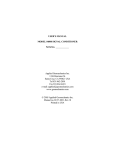
USER’S MANUAL
“IRIS”
TILT SWITCH AND CONTROLLER
Serial No.________________
High-Gain Version (±10 degrees)
Standard Version (±25 degrees)
Wide-Angle Version (±50 degrees)
1336 Brommer Street
Santa Cruz, CA 95062 USA
Tel (831) 462-2801
Fax (831) 462-4418
[email protected]
www.geomechanics.com
Copyright ©2006 by Applied Geomechanics Inc. All rights reserved.
Document No. B-06-1001 Rev. A
IRIS
TM
Tilt Switch and Controller
The IRIS Tilt Switch and Controller is a powerful
control device that enables you to measure and
respond to rotational movements in any direction with
reference to the unchanging gravity vector. Use IRIS
to maintain platform levelness, avoid tipover conditions,
prevent out-of-range movement, and for many other
control requirements.
IRIS detects angular position with an on-board
electrolytic tilt sensor, which has no mechanical
moving parts to break or wear out. The standard
firmware includes five user-programmable set points
for tilts in different directions. When a selected
threshold is reached, the circuitry sets the output high
on one of the pins in the H3 control connector. Three
additional control outputs are available for firmware
upgrades in custom applications.
IRIS is also a multi-featured inclinometer, which
contributes to its powerful control capabilities. Data
sampling rates, which are also the threshold checking
rates, are user-selectable, and inclination data in
ASCII
High-Gain Version
ANGULAR RANGE
RESOLUTION
ACCURACY
TIME CONSTANT, T
NATURAL FREQUENCY
TEMPERATURE COEF.
SAMPLE RATES
DATA STORAGE
SERIAL OUTPUT
DATA FORMATS
CONTROL OUTPUTS
POWER REQUIREMENTS
ENVIRONMENTAL
CONNECTIONS
DIMENSIONS & WEIGHT
format can be continuously output to external devices.
Firmware commands include averaging, autozero and
other powerful functions. Call us for details or to place an
order!
Standard Version
Wide-Angle Version
±10 degrees (20 degree span)
0.005 degree
±25 degrees (50 degree span)
±50 degrees* (100 deg. span)
0.012 degree
0.025 degree
±1% of full span
150 msec; output is proportional to 1 - e -t/T where t = time in seconds
7 Hz; available with viscous sensor to filter vibrations
Span: +0.03%/ oC, Zero: 10-20 arc sec/ oC typical
User-selectable from 10/second to 1/hour
512 kB of nonvolatile Flash Memory available as an option
RS232 or RS422(485), full duplex. Baud rate: 9600 (default), 19200, 28800, 57600, 115200, 230400
Formats: NMEA XDR, Trimble proprietary, Ashtech compatible, Simple (x, y, temperature, serial number)
8 TTL-compatible CMOS control outputs (0-5 VDC): 5 with user-programmable set points, 3 available for custom
applications. Each channel can source up to 20 mA, not to exceed 100 mA for all 8 channels.
7-28 VDC @ 27 mA, 250 mV peak-to-peak ripple max., reverse polarity and surge protected.
−40° to +85°C operating and storage; 90% humidity, noncondensing
Three 60cm (2 ft) cables included: Signal (H1), Power (H2), Control Outputs (H3)
67 x 67 x 25mm max. (2.6 x 2.6 x 1.0 inches); 31g (1.1 oz)
*greater range available
IRIS Tilt Switch Order Numbers
Version
RS232
RS422(485)
High Gain
Standard
Wide Angle
98021-03
98021-01
98021-02
98021-09
98021-07
98021-08
Accessories & Upgrades
Power Kit: 100-240 VAC wall transformer,
power cable with connectors
Critically damped sensor to filter vibrations
Mounting plate & hardware
512 kB Flash memory upgrade
1336 Brommer Street, Santa Cruz, CA 95062 USA Tel.(831) 462-2801, Fax (831) 462-4418
[email protected] z www.geomechanics.com
B-06-1001, Rev. A ©2006 Applied Geomechanics Inc.
Part No.
84091
VISCDAMP
84089
48543
IRISTM Tilt Switch and Controller
A Full-Featured Inclinometer
IRIS is a versatile biaxial clinometer that measures
rotational movement in two orthogonal vertical planes.
Serial ASCII data are output as either RS232 or
RS422(485) signals for recording by an external
terminal or computer. Important features are firmwarecontrolled and user-selectable. These include output
data rates and formats, signal averaging, autozero
(nulling), and internal data storage (logging). Several
output data formats are provided, all of which include
X tilt, Y tilt, Temperature and Serial Number
information.
A Powerful Control Device
The firmware on the standard IRIS board has 5 user
programmable thresholds. When a tilt measurement is
taken, it is compared to each of these thresholds: +X
tilt, -X tilt, +Y tilt, -Y tilt and tilt in any direction. If
the measurement exceeds one or more of the thresholds,
the corresponding output pin(s) in the H3 connector,
are set high (5V), as shown below. If the threshold is
not exceeded, the output remains at 0 Volts. The
reference angle for the threshold measurement is
selected using the autozero command. Threshold
checking may be turned off with a single firmware
command when it is not needed.
The standard IRIS firmware also allows the user to set
the hysteresis of the control thresholds. The hysteresis
is used as follows: After an H3 output pin is set high, it
is not set low again until the tilt reading has reached a
level that is below the threshold by an amount equal to
the hysteresis (see diagram).
IRIS includes 3 additional control output pins in the H3
connector, bringing the total to 8. The 3 additional pins
are not active in the regular versions of the product, but
may be implemented for your application by custom
programming by our engineers. Each of the 8 control
outputs is separately programmable. Another custom
option is “normally high” control output instead of the
standard “normally low” output. With “normally high”
controls the voltage level of the H3 pin is 5V until a
threshold is reached, at which time it switches to 0V.
In the regular versions of IRIS the control pins in
connector H3 are all set high for approximately 150
milliseconds on power up, after which they reset to
their “normally low” value of 0V until a tilt threshold is
detected.
Connector Pinout Tables
H1 Pin
1
2
3
4
5
6
7
8
Function
Power (7-28 VDC)
Ground
Tx (RS232)
Rx(RS232)
Tx+(RS422)
Tx−(RS422)
Rx−(RS422)
Rx+(RS422)
H2 Pin
1
2
3
4
5
6
7
8
Function
Power (7-28 VDC)
Ground
Ground
Reserved
Reserved
Reserved
Reserved
Reserved
H3 Pin
Function
1
-X tilt threshold
2
+X tilt threshold
3
-Y tilt threshold
4
+Y tilt threshold
5
Optional threshold*
6
Optional threshold*
7
Optional threshold*
8
Threshold in any direction
9
Ground
10
3.3 VDC output
* Custom firmware only
1336 Brommer Street, Santa Cruz, CA 95062 USA Tel.(831) 462-2801, Fax (831) 462-4418
[email protected] z www.geomechanics.com
B-06-1001, Rev. A ©2006 Applied Geomechanics Inc.
IRISTM Tilt Switch and Controller
Figure 1. IRIS dimensions
Specifications are subject to change without notice as the result of ongoing development.
1336 Brommer Street, Santa Cruz, CA 95062 USA Tel.(831) 462-2801, Fax (831) 462-4418
[email protected] z www.geomechanics.com
B-06-1001, Rev. A ©2006 Applied Geomechanics Inc.
IRISTM Tilt Switch and Controller
Figure 2
Figure 3
1336 Brommer Street, Santa Cruz, CA 95062 USA Tel.(831) 462-2801, Fax (831) 462-4418
[email protected] z www.geomechanics.com
B-06-1001, Rev. A ©2006 Applied Geomechanics Inc.
IRISTM Tilt Switch and Controller
Figure 4
Figure 5
1336 Brommer Street, Santa Cruz, CA 95062 USA Tel.(831) 462-2801, Fax (831) 462-4418
[email protected] z www.geomechanics.com
B-06-1001, Rev. A ©2006 Applied Geomechanics Inc.
IRISTM Tilt Switch and Controller
Figure 6
1336 Brommer Street, Santa Cruz, CA 95062 USA Tel.(831) 462-2801, Fax (831) 462-4418
[email protected] z www.geomechanics.com
B-06-1001, Rev. A ©2006 Applied Geomechanics Inc.
IRISTM Tilt Switch and Controller
1
Connectors and Pinouts
Your IRIS Tilt Switch and Controller uses three connectors on the printed circuit assembly: H1, H2
and H3. Pin assignments for the three connectors are shown in Figures 1-6. We have provided a short
cable whip (pigtail) for each of these connectors as part of the normal IRIS product package (assembly
98021-XX). These whips include two serial cables, each terminated with a DB9 connector. One is for
RS232 communications, the other for RS422(485). All serial connections are made through H1.
Power for the circuit is supplied using the power and ground pins on H1 or H2. The two grounds
on H2 pins 2 and 3 are common on the IRIS printed circuit assembly. Pins 4-8 of H2 are reserved for new
product features that are not yet implemented. Do not connect to or short pins 4-8 of H2.
All control functions are provided through the H3 connector. Pins 1-4 and 8 of H3 are switched
outputs. H3 pin 9 (ground) is common with the ground pins in H1 and H2. For control applications we
recommend the use of H3 pin 9 as ground to avoid the possibility of ground loops. H3 pins 5-7 are
reserved for custom firmware versions. When using the standard firmware, do not connect to or short pins
5-7 of H3.
2
Communicating with the IRIS Tilt Switch and Controller
The most common way of communicating with the IRIS Tilt Switch and Controller is using a
terminal emulator program (e.g. Terminal in Windows 3.1 or HyperTerminal in Windows 95 and later).
All communication are performed through the send (transmit) and receive wires of the serial port. The
default parameters for the serial port are set to no parity, 8 bits and 1 stop bit with no hardware or software
flow control. The baud rate is the only parameter that is user-selectable. The default baud rate is 9600.
Baud rates up to 230400 are supported.
1.1
Firmware Command Format
The format of commands issued by the host is:
*9900<command><CR><LF>
Valid commands are listed in Section 3.
The input/output processing on the serial port of the IRIS circuit is as follows:
(1)
Input is read until a <CR> or <LF> (carriage return or line feed) is received. (On a PC, this usually
means pressing the ‘Enter’ or ‘Return’ key.)
(2)
When a line is received, it is parsed to see if it is a command of the device. If it is not, then it is echoed
back out, terminated with a <CR> <LF> and we go back to step (1). All strings that are not commands
for the unit are echoed. If the command is for the device, we then go to step (3).
(3)
The command is processed and we return to step (1). All incoming characters are buffered (up to 1000)
while the command is being processed. If the command is for ID 99 and echoing of 99 commands is
B-06-1001, Rev. A
1
IRISTM Tilt Switch and Controller
enabled, the command is echoed after the command result is transmitted.
Default output of the MD900-T running firmware version 5 and up is a simple (“SIM”) comma-delimited string
consisting of X tilt in degrees, Y tilt in degrees, temperature in ºC, and the serial number of the device. Optional
outputs consist of a Trimble Navigation proprietary ASCII string with X (Roll) and Y (Pitch) tilts in degrees,
and two output formats that follow NMEA Standard 0183, version 2.1, October 15, 1995. This standard may be
obtained from:
National Marine Electronics Association (NMEA)
National Office
P.O. Box 3435
New Bern, NC 28564-3435 USA
Tel: 919/638-2626
Fax: 919/638-4885
1.2
Firmware Command Summary
The list below summarizes the most important user-accessible firmware commands. Precede these commands
with the string *9900. See Appendix A for additional details.
XY
Outputs a single tilt and temperature measurement. The format of the output
depends on the setting of the SO command.
SO-xxx
Selects the output format for the XY command. “xxx” selects format as follows:
ASH: Ashtech compatible NMEA format
SIM: Simple x,y,t,sn output string (default)
XDR: NMEA XDR format
TCM: Trimble Navigation proprietary pitch (Y) and roll (X) string
BAE: BAE Systems encoded 11-byte string containing a sync packet, x, y, t,
SN, and checksum information. Advanced users only—typically for
embedded system integration.
XY-MEMS
Stores tiltmeter readings at selected output rate in nonvolatile memory.
(Versions 5.1 and higher)
XY-MEMD
Downloads data from nonvolatile memory. (Versions 5.1 and higher)
XY-M1
Sets the tiltmeter to Mode-1 operation.
XYVR
Displays the sign-on string.
ID
Sets the ID of units in the daisy chain (not currently implemented).
XY-TR-PASH-ON
Translates the Paros provided $PASHS,XDR,P sentences to standard
NMEA XDR format.
XY-TR-PASH-OFF
Turns off translation of $PASHS,XDR,P sentences.
B-06-1001, Rev. A
2
IRISTM Tilt Switch and Controller
XY-EP
Enables power on message.
XY-SP
Disables power on message.
XY-EE
Enables echoing of global 99 commands.
XY-SE
Disables echoing of global 99 commands.
XY-SET-BAUDRATE,x
Sets baud rate to value of x in bits per second. Selectable values include 9600,
19200, 28800, 57600, 115200 and 230400 baud.
XY-SET-N-SAMP,x
Sets number of samples that are averaged before a reading is transmitted;
x may have any value from 1 to 1000. Changing this value may also change the
output rate.
XY-SET-RSMODE,x
Selects serial output mode:
x=0
RS232
x=1
RS485 (RS422)
XY-AUTOZ
Turns on auto zero function.
XY-AUTOZOFF
Turns off auto zero function.
XYCx
Continuously sends XY data where x determines output rate as follows:
x = 0:
x = 1:
x = 2:
x = 3:
x = 4:
x = 5:
x = 6:
x = 7:
x = 0A:
x = 1A:
x = 2A or x = A:
8-10 outputs per second
4 outputs per second
1 output per second (default)
1 output every 10 seconds
1 output every 60 seconds
1 output every hour
1 output every 12 hours
1 output every 24 hours
Averaging of the 8-10 outputs per second data
Averaging of the 4 outputs per second data
Averaging of the 1 output per second data
Once initiated, continuous output remains in effect until turned off with the
XYC-OFF command (see below).
XYC-OFF
Turns off XYC mode.
XY-SET-CTRL-ON
Enables control feature.
XY-SET-CTRL-OFF
Disables control feature.
XY-SET-CTRLTEST-ON
Sets the control pin high (+5 VDC).
XY-SET-CTRLTEST-OFF
Sets the control pin low (0 VDC).
B-06-1001, Rev. A
3
IRISTM Tilt Switch and Controller
XY-SET-THRESHOLD,x+,x-,y+,ySets the control thresholds. The reference angle for threshold
measurement is selected using the XY-AUTOZ command.
XY-SET-HYST,k
Sets the control hysteresis.
XY-DUMP-SETTINGS
Dumps settings of device.
XY-DUMP2
Dumps extended settings of device.
2
Setting the Control Thresholds
The firmware commands for turning the control feature of IRIS on and off, and for setting the
control thresholds (set points) are summarized in Figure 6 and in Section 1.2. They are described in greater
detail in Section 4. The reference angle for each control threshold is the zero angle, as set by the autozero
command, XY-AUTOZ. If the unit is not autozeroed, the reference angle is the zero angle set during the
instrument’s factory calibration.
If you plan to rotate IRIS in the X or Y direction only, set the positive and negative X and Y
thresholds using the XY-SET-THRESHOLD,x+,x-,y+,y- command. If you need to detect a tilt threshold in
any direction (not just the X or Y direction), set the “General Alarm” threshold (H3 pin 8, Figure 6) in the
following manner:
Set x+ = y+ (a positive number)
Set x− = y− (a positive or a negative number)
When tilt > x+, pin H3-8 goes high.
When tilt < x− and x− > 0, pin H3-8 goes high.
When x− ≤ 0, only the positive threshold is used for the “General Alarm”.
Hysteresis (Figure 6) is applied to all thresholds in the same manner. Set the hysteresis using the
XY-SET-HYST,k command.
Caution: Always verify that your control thresholds are functioning as intended before using your IRIS
Tilt Switch & Controller in critical applications. Applied Geomechanics Inc. shall not be liable for any
direct, indirect, special, incidental or consequential damages!
3
Sample Data Using the XY Command
When you use your IRIS circuit to collect tilt data, the most commonly used command is the XY
command, which returns the X and Y tilt angles in degrees and the internal temperature of the MD900-T in ºC.
The format of the returned data depends on the setting of the SO command. The returned data are averages of a
series of readings. The number of samples used in the average is set by the XY-SET-N-SAMP command. The
following lines illustrate the format of the data returned by the XY command for the range of possible SO
settings:
SO = “ASH.” Ashtech compatible NMEA output string which returns the North-South (Y) and East-West (X)
tilt angle in degrees and the internal temperature of the MD-900-T in ºC:
B-06-1001, Rev. A
4
IRISTM Tilt Switch and Controller
$PASHS,XDR,A,004.261,D,N,A,004.280,D,E,C,021.288,C,T-N1346
$PASHS,XDR,A,004.261,D,N,A,004.280,D,E,C,021.306,C,T-N1346
$PASHS,XDR,A,004.261,D,N,A,004.280,D,E,C,021.298,C,T-N1346
$PASHS,XDR,A,004.261,D,N,A,004.280,D,E,C,021.332,C,T-N1346
SO = “SIM” (default). Simple X,Y,T,SN output which returns the X and Y tilt angle in degrees and the internal
temperature of the MD-900-T in ºC:
$-00.619,000.023,018.910,N0000
$-00.619,000.023,018.923,N0000
$-00.620,000.024,018.932,N0000
$-00.620,000.023,018.951,N0000
SO = “XDR.” Standard NMEA XDR output string which returns the North-South (Y) and East-West (X) tilt
angle in degrees and the internal temperature of the MD-900-T in ºC:
$YXXDR,A,000.034,D,N,A,-00.625,D,E,C,021.651,C,T-N0000*47
$YXXDR,A,000.034,D,N,A,-00.624,D,E,C,021.675,C,T-N0000*40
$YXXDR,A,000.034,D,N,A,-00.624,D,E,C,021.686,C,T-N0000*4C
$YXXDR,A,000.034,D,N,A,-00.625,D,E,C,021.707,C,T-N0000*45
SO = “TCM.” Proprietary Trimble Navigation pitch (Y-tilt) and roll (X-tilt) output string which returns the tilt
angle in degrees and a checksum:
$P-00.907R002.186*1C
$P-00.906R002.183*18
$P-00.908R002.191*15
$P-00.908R002.191*15
$P-00.905R002.190*19
SO = “BAE.” Advanced users only, using the D711-2A(4X). BAE Systems encoded 11-byte output which
returns two synchronization bytes, the X (2 bytes) and Y (2 bytes) tilt angle, the internal temperature of the
tiltmeter (2 bytes), the serial number (2 bytes), and a checksum byte:
Uª
Ä$é
TæUª
Ä$ä
TáUª
Ä$ß
TÜUª
Ä$é
Tæ
The BAE output string is not clearly decipherable by HyperTerminal, which sometimes hides characters
that it has received and cannot understand. Because of this, it is difficult, if not impossible, to interpret data
in this format. The above output string shows four outputs taken from HyperTerminal. This encoded
output command is typically used to communicate with embedded systems, as they can view raw data and
perform fast translations.
The first synchronization byte is 0x55, the second is 0xAA. The X and Y bytes use 0.0000277 angular degrees
per LSB, hence the total output range of this output mode is limited to the model D711-2A(4X). The
temperature uses 0.004 degrees Celsius per LSB. The serial number is a two byte integer. The checksum byte
is the result of ANDing bytes 2-7 with 255.
B-06-1001, Rev. A
5
IRISTM Tilt Switch and Controller
BAE output mode reduces the total number of characters per output to 11 bytes, while transferring the same
data as the SIM output mode, which requires 33 bytes. BAE mode also includes checksum and frame
synchronization bytes. Refer to Appendix A, Firmware Commands, to decode the output.
4
Firmware Commands
Valid commands are listed below. Some commands have more than one string to trigger the command.
“tt” stands for the target ID (99) and “ss” stands for the source ID (00). Settings stored in nonvolatile memory
remain in effect until disabled, even after a power cycle.
--------------------------------------XY
Outputs a single tilt measurement. The format of the output
depends on the setting of the SO command.
Syntax: *ttssXY<CR><LF>
Error Strings: None.
Default: N/A
Persistence: N/A
Example:
command: *9900XY<CR><LF>
response: $YXXDR,A,-00.920,D,N,A,-00.210,D,E,C,030.045,C,T-N1212*57
--------------------------------------SO
Selects the output format for the XY command.
are:
The possible formats
-SIM
$x.x,y.y,t.t,sn<CR><LF>
|
|
|
|
|
|
|
Serial number
|
|
Temperature of tiltmeter
|
Y-tilt value in degrees
X-tilt value in degrees
Example:
$-00.920,-00.210,030.045,N1212
-XDR
$YXXDR,A,x.x,D,N,A,x.x,D,E,C,x.x,C,T-sn*hh<CR><LF>
| | | | | | | | | | | | | |
| | | | | | | | | | | | | Checksum
| | | | | | | | | | | | Serial number
| | | | | | | | | | | Comment, T for temperature
| | | | | | | | | | Units, C=degrees C
| | | | | | | | | Temperature of tiltmeter
| | | | | | | | Data Type, C=Temperature
| | | | | | | Comment, E for East/West (X) direction
| | | | | | Units, M=microradians, D=degrees
| | | | | X (E)-tilt value
| | | | Data Type, A=Angular
| | | Comment, N for North/South (Y) direction
| | Units, M=microradians, D=degrees,
| Y (N)-tilt value
Data Type, A=Angular
Example:
$YXXDR,A,-00.920,D,N,A,-00.210,D,E,C,030.045,C,T-N1212*57
B-06-1001, Rev. A
6
IRISTM Tilt Switch and Controller
-ASH
$PASHS,XDR,A,x.x,D,N,A,x.x,D,E,C,x.x,C,T-sn<CR><LF>
| | | | | | | | | | | | |
| | | | | | | | | | | | Serial number
| | | | | | | | | | | Comment, T for temperature
| | | | | | | | | | Units, C=degrees C
| | | | | | | | | Temperature of tiltmeter
| | | | | | | | Data Type, C=Temperature
| | | | | | | Comment, E for East/West direction
| | | | | | Units, M=microradians, D=degrees
| | | | | X (E)-tilt value
| | | | Data Type, A=Angular
| | | Comment, N for North/South direction
| | Units, M=microradians, D=degrees
| Y (N)-tilt value
Data Type, A=Angular
Example:
$PASH,XDR,A,-00.920,D,N,A,-00.210,D,E,C,030.045,C,T-N1212
-TCM
$Py.y,Rx.x*hh<CR><LF>
|
|
|
|
|
|
|
|
CheckSum
|
Roll= X-tilt value in degrees
Pitch= Y-tilt value in degrees
Example:
$P-00.905R002.190*19
-BAE
abcdefghijk
|||||||||||
||||||||||Byte 10(k): Checksum of bytes 2-7 ANDed with decimal 255
||||||||||
||||||||Byte 8-9(i,j): Serial number in hexadecimal format
||||||||
||||||Byte 6-7(g,h): Temperature in Deg. C. Bits 14 – 0 = magnitude
||||||
(LSB bit = 0.004 Deg. C.), Bit 15 = sign
||||||
||||Byte 4-5(e,f): Y Axis Level Data. Bits 14 – 0 = magnitude
||||
(LSB bit = 0.0000277 degrees), Bit 15 = sign
||||
||Byte 2-3(c,d):
X Axis Level Data. Bits 14 – 0 = magnitude
||
(LSB bit = 0.0000277 degrees), Bit 15 = sign
||
|Byte 1(b): 0xAA, 2nd Synchronization Byte
|
Byte 0(a): 0x55, 1st Synchronization Byte
Syntax: *ttssSO-<output format><CR><LF>
Error Strings:
ERR XY-SO BAD PARAMETER
<output format> was invalid.
ERR XY-SO PARSE ERROR
Could not parse <output format>.
Default: SIM
Persistence: Setting is stored in nonvolatile memory.
Example:
command: *9900SO-XDR<CR><LF>
response: <none>
B-06-1001, Rev. A
7
IRISTM Tilt Switch and Controller
--------------------------------------XY-MEMS
Stores the tiltmeter readings in simple format (SO-SIM) at selected
output rate in nonvolatile memory.
Syntax: *ttssXY-MEMS<CR><LF>
Error Strings: None.
Default: N/A
Persistence: Subsequent tiltmeter readings stored in nonvolatile memory
until memory is full. Maximum of approximately 150 lines of data.
Example:
command: *9900XY-MEMS<CR><LF>
response: <none>
--------------------------------------XY-MEMD
Downloads the tiltmeter readings in nonvolatile memory to PC.
Syntax: *ttssXY-MEMD<CR><LF>
Error Strings: None.
Default: N/A
Persistence: Stored tiltmeter readings downloaded at rate of
1 per second to PC in ASCII comma-delimited string.
Example:
command: *9900XY-MEMD<CR><LF>
response: $start:11-11-1997 18:43:09 4/sec
$000.699,-01.022,025.116,N1028
$000.699,-01.022,025.116,N1028
$000.698,-01.021,025.110,N1028
$000.698,-01.022,025.122,N1028
--------------------------------------XY-M1
Sets the operation to Mode 1. This command groups several
other commands together for convenience. The commands that
are issued are:
XY-TR-PASH-ON
XY-SO-XDR
XY-SE
XY-SP
Syntax: *ttssXY-M1<CR><LF>
Error Strings: None.
Default: N/A
Persistence: Setting is stored in nonvolatile memory.
Example:
command: *9900XY-M1<CR><LF>
response: AGI Model D711-2A(4X) Firmware V2.2 SN-N1212 ID01
B-06-1001, Rev. A
8
IRISTM Tilt Switch and Controller
--------------------------------------XYVR
Displays the sign-on string.
Syntax: *ttssXYVR<CR><LF>
Error Strings: None.
Default: N/A
Persistence: N/A
Example:
command: *9900XYVR<CR><LF>
response: AGI Model D711-2A(4X) Firmware V5.2 SN-N1212 ID01
--------------------------------------ID
This command is not currently supported. Sets the ID of units
in the daisy chain. The first device in the serial chain sets
its ID to the source ID plus one (ss+1), and then outputs a the
ID command to the next device with the source ID set to its new
ID. The target ID of this command must be 99.
Syntax: *99ssID<CR><LF>
Error Strings: None.
Default: 01
Persistence: Setting is stored in nonvolatile memory.
Example:
command: *9900ID<CR><LF>
response: *9901ID<CR><LF>
--------------------------------------XY-TR-PASH-ON
Translates the Paros provided $PASHS,XDR,P sentences to
standard NMEA XDR format. An example input PASH string would
be:
$PASHS,XDR,P,1.000123,B,SN123,C,22.12,C,SN123,H,32.11,P,SN123<CR><LF>
The translated string would then be:
$WIXDR,P,1.000123,B,SN123,C,22.12,C,SN123,H,32.11,P,SN123*hh<CR><LF>
Syntax: *ttssXY-TR-PASH-ON<CR><LF>
Error Strings: None.
Default: Off.
Persistence: Setting is stored in nonvolatile memory.
Example:
command: *9900XY-TR-PASH-ON<CR><LF>
response: <none>
B-06-1001, Rev. A
9
IRISTM Tilt Switch and Controller
--------------------------------------XY-TR-PASH-OFF Turns off translation of $PASHS,XDR,P sentences.
Syntax: *ttssXY-TR-PASH-OFF<CR><LF>
Error Strings: None.
Default: N/A
Persistence: Setting is stored in nonvolatile memory.
Example:
command: *9900XY-TR-PASH-OFF<CR><LF>
response: <none>
--------------------------------------XY-EP
Enables power on message. Power on message is:
AGI Tiltmeter
Firmware V5.2 SN-N1212 ID01
Where V5.2 is the firmware version, SN-N1212 is the serial
number of the device and ID01 is the target's ID.
Syntax: *ttssXY-EP<CR><LF>
Error Strings: None.
Default: On.
Persistence: Setting is stored in nonvolatile memory.
Example:
command: *0100XY-EP<CR><LF>
response: <none>
--------------------------------------XY-SP
Disables power on message.
Syntax: *ttssXY-SP<CR><LF>
Error Strings: None.
Default: N/A
Persistence: Setting is stored in nonvolatile memory.
Example:
command: *9900TR-SP<CR><LF>
response: <none>
--------------------------------------XY-EE
Enables echoing of global 99 commands. If the unit receives
a command for ID 99, then the unit will respond to the command
and echo the command when it is done.
Syntax: *ttssXY-EE<CR><LF>
Error Strings: None.
Default: On.
Persistence: Setting is stored in nonvolatile memory.
Example:
command: *0100XY-EE<CR><LF>
response: <none>
B-06-1001, Rev. A
10
IRISTM Tilt Switch and Controller
--------------------------------------XY-SE
Disables echoing of global 99 commands. If the unit receives
a command for ID 99, then the unit will respond, but the
unit will NOT echo the command when it is done.
Syntax: *ttssXY-SE<CR><LF>
Error Strings: None.
Default: N/A
Persistence: Setting is stored in nonvolatile memory.
Example:
command: *0100XY-SE<CR><LF>
response: <none>
--------------------------------------XY-SET-BAUDRATE,x
Changes communications baud rate. Maximum supported baud
rate is 57,600 baud. The parameter x is an integer with up
to six places, defining the baud rate as follows:
9600
19200
28800
57600
115200
230400
=
=
=
=
=
=
9600 baud
19200 baud
28800 baud
57600 baud
115200 baud
230400 baud
Syntax: *ttssXY-SET-BAUDRATE,x<CR><LF>
Error Strings: ERR XY-SET-BAUDRATE,x PARSE ERROR.
Default: 9600
Persistence: Setting is stored in nonvolatile memory.
Example:
command: *9900XY-SET-BAUDRATE,57600<CR><LF>
response: <none>
--------------------------------------XY-SET-N-SAMP,x
Sets the number of samples that are averaged before a reading
is transmitted. The parameter x is an integer between 1 and
1000 equal to the number of samples that are averaged.
Syntax: *ttssXY-SET-N-SAMP,x<CR><LF>
Error Strings: None.
Default: Depends on data output rate, as specified by the XYCx command.
The default numbers of samples averaged for each data rate are:
XYC0:
XYC1:
XYC2:
XYC3:
XYC4:
XYC5:
XYC6:
XYC7:
28
100
460
500
500
500
500
500
If the number of samples specified exceeds the number listed above for
XYC0, XYC1 or XYC2, the microprocessor reduces the data output rate
until it has enough time to collect and average all of the samples.
B-06-1001, Rev. A
11
IRISTM Tilt Switch and Controller
Persistence: Once initiated, the same averaging remains in effect even
with power cycle. (Setting is stored in nonvolatile memory.) Can be
changed by reissuing the command with a different value for x, or by
changing the output rate with the XYCx command.
Example:
command: *9900XY-SET-N-SAMP,250<CR><LF>
response: <none>
--------------------------------------XY-SET-RSMODE,x
Sets output protocol to RS232 or RS485(RS422), as follows:
x = 0: RS232
x = 1: RS485(RS422)
Syntax: *ttss XY-SET-RSMODE,x<CR><LF>
Error Strings: None.
Default: Set in factory to customer specification.
Persistence: Once initiated, remains in effect even with power cycle.
(Setting is stored in nonvolatile memory.)
Example:
command: *9900XY-SET-RSMODE,0<CR><LF>
response: <none>
CAUTION:
If you change the output protocol, you will no longer be able to
communicate with the tiltmeter unless you have the correct
interconnect cable.
--------------------------------------XY-AUTOZ
Turns autozero function on, causing tiltmeter to subtract current X
and Y readings from all subsequent X and Y readings.
Syntax: *ttssXY-AUTOZ <CR><LF>
Error Strings: None.
Default: Off.
Persistence: Setting is stored in nonvolatile memory.
Example:
command: *9900XY-AUTOZ<CR><LF>
response: <none>
--------------------------------------XY-AUTOZOFF
Turns autozero function off, causing tiltmeter to display
non-biased (unshifted) position readings.
Syntax: *ttssXY-AUTOZ-OFF<CR><LF>
Error Strings: None.
Default: Off.
Persistence: Setting is stored in nonvolatile memory.
Example:
command: *9900XY-AUTOZ-OFF<CR><LF>
response: <none>
B-06-1001, Rev. A
12
IRISTM Tilt Switch and Controller
-------------------------------------XYCx
Continuously sends XY data - even after power has been turned off and
then on again. Timing is determined by the microprocessor’s crystal and
is approximate. The parameter x is an integer between 1 and 7, the
letter A, or 0A, 1A, or 2A.
An A indicates the use of the moving average function, in which the
moving average of the data is output. When the moving average function
is used, the first output is delayed until the first n readings have
been taken, where n is the number of readings to be averaged. After
that, the outputs occur at the same rate as the readings. For example,
the command XYC2A outputs the moving average of the same data that would
be output if the user issued the command XYC2. Since XYC2 outputs data
once per second, XYC2A also outputs once per second. However, the first
output occurs after a four-second delay, in which the first four
readings (at a rate of 1 per second) are averaged. The second output is
the average of readings 2-5, the third output is the average of readings
3-6, and so on, creating an output rate equal to that of XYC2.
The parameter x determines rate of continuous output as follows:
x = 0: 8-10 per second
1: 4 per second
2: 1 per second
3: 1 every 10 seconds
4: 1 every 60 seconds
5: 1 every 60 minutes
6: 1 every 12 hours
7: 1 every 24 hours
0A: Average of 8-10 outputs/sec data. 10 readings are averaged.
1A: Average of 4 outputs/second data. 4 readings are averaged.
2A or A: Average of 1 output/second data. 4 readings are averaged.
Syntax: *ttssXYCx<CR><LF>
Error Strings: None.
Default: Off.
Persistence: Once initiated, continuous output remains in effect even
with power cycle. (Setting is stored in nonvolatile memory.) Must be
turned off using the XYC-OFF command (see below).
Example (with SO=”SIM”):
command: *9900XYC1<CR><LF>
response: $-00.699,000.070,020.290,N0000
$-00.699,000.071,020.309,N0000
$-00.699,000.071,020.313,N0000
$-00.699,000.071,020.330,N0000
$-00.699,000.071,020.348,N0000
$-00.700,000.070,020.360,N0000
---------------------------------------XYC-OFF Turns off XYC mode.
Syntax: *ttssXYC-OFF<CR><LF>
Error Strings: None.
Default: N/A.
Persistence: Setting is stored in nonvolatile memory.
Example:
command: *0100XYC-OFF<CR><LF>
response: *0100XYC-OFF<CR><LF>
B-06-1001, Rev. A
13
IRISTM Tilt Switch and Controller
--------------------------------------XY-SET-CTRL-ON
Enables control feature. If the tilt exceeds either threshold
in any direction, the control pin will go high (+5 VDC) until
the tilt falls below the positive threshold value minus the
hysteresis value, or falls above the negative threshold value
plus the hysteresis value.
Syntax:
*ttssXY-SET-CTRL-ON<CR><LF>
Error Strings:
Default:
None.
On.
Persistence:
Setting is stored in nonvolatile memory.
Example:
command: *9900XY-SET-CTRL-ON<CR><LF>
response: <none>
--------------------------------------XY-SET-CTRL-OFF
Disables control feature. The control pin will remain at
ground potential (0 VDC) unless the user issues the command
XY-SET-CTRLTEST-ON or turns the control feature on again by
issuing the command XY-SET-CTRL-ON.
Syntax:
*ttssXY-SET-CTRL-OFF<CR><LF>
Error Strings:
Default:
None.
On.
Persistence:
Setting is stored in nonvolatile memory.
Example:
command: *9900XY-SET-CTRL-OFF<CR><LF>
response: <none>
--------------------------------------XY-SET-CTRLTEST-ON Sets the control pin high (+5 VDC), regardless of whether
control feature is on or off. Convenient for testing
control functionality regardless of tilt.
Syntax:
*ttssXY-SET-CTRLTEST-ON<CR><LF>
Error Strings:
Default:
None.
Off.
Persistence: Control pin stays high until the user issues the command
XY-SET-CTRLTEST-OFF or disconnects power.
Example:
command: *9900XY-SET-CTRLTEST-ON<CR><LF>
response: <none>
B-06-1001, Rev. A
14
IRISTM Tilt Switch and Controller
--------------------------------------XY-SET-CTRLTEST-OFF Sets the control pin low (0 VDC). If the control feature
is on and the tilt falls above the positive threshold value
minus the hysteresis value, or falls below the negative
threshold value plus the hysteresis value, the control pin
may go high again immediately. XY-SET-CTRL-OFF turns off
the control feature altogether.
Syntax:
*ttssXY-SET-CTRLTEST-OFF<CR><LF>
Error Strings:
Default:
None.
Off.
Persistence: None. If the control feature is on and the tilt exceeds
the hysteresis value, the control pin may go high again immediately.
Example:
command: *9900XY-SET-CTRLTEST-OFF<CR><LF>
response: <none>
--------------------------------------XY-SET-THRESHOLD,x+,x-,y+,ySets the control thresholds. The parameter x+ is
the positive threshold for the x axis in the
current output units (default is degrees), and so
on for parameters x-, y+, and y-. If the tilt
exceeds either threshold on either axis, and the
control feature is on, the control pin goes high
(+5 VDC) until the tilt falls below the positive
threshold value minus the hysteresis value, or
falls above the negative threshold value plus the
hysteresis value.
Syntax:
*ttssXY-SET-THRESHOLD,x+,x-,y+,y-<CR><LF>
Error Strings:
Default:
x+
xy+
y-
Persistence:
ERR XY-SET-THRESHOLD PARSE ERROR.
=
=
=
=
1
-1
1
-1
Setting is stored in nonvolatile memory.
Example:
command: *9900XY-SET-THRESHOLD,5,-3.244,4.0,0<CR><LF>
response: <none>
B-06-1001, Rev. A
15
IRISTM Tilt Switch and Controller
--------------------------------------XY-SET-HYST,x
Sets the control hysteresis, where the parameter x is the
hysteresis value in the current output units (default is
degrees). If the tilt exceeds either threshold on either
axis, and the control feature is on, the control pin remains
high (+5 VDC) until the tilt falls below the positive
threshold value minus the hysteresis value, or falls above the
negative threshold value plus the hysteresis value.
Syntax:
*ttssXY-SET-HYST,x<CR><LF>
Error Strings:
Default:
ERR XY-SET-HYST PARSE ERROR.
0
Persistence:
Setting is stored in nonvolatile memory.
Example:
command: *9900XY-SET-HYST,0.5<CR><LF>
response: <none>
--------------------------------------XY-DUMP-SETTINGS
Dumps settings of device.
Syntax: *ttssXY-DUMP-SETTINGS<CR><LF>
Error Strings: None.
Default: N/A
Persistence: N/A
Example:
command: *9900XY-DUMP-SETTINGS
response:
APPLIED GEOMECHANICS Tiltmeter
Firmware V5.0 SN-N2144 ID01
01: Vbias= 2047.000000000 2047.000000000 NaN
NaN
01: Vgain=
0.005000000
0.005000000
0.000610350
0.000610350
01: Vmin: -2.50 -2.50
2.50
2.50
01: Vmax:
2.50
2.50
2.50
2.50
01: a0=
0.00000
0.00000
0.00000
0.00000
0.00000
0.00000
01: a1=
0.00000
0.00000
0.00000
0.00000
0.00000
0.00000
01: a2=
0.00000
0.00000
0.00000
0.00000
0.00000
0.00000
01: a3=
0.00000
0.00000
0.00000
0.00000
0.00000
0.00000
01: Tcoef 0: Ks=
0.0003 Kz=
0 Tcal=
25
01: Tcoef 1: Ks=
0.0003 Kz=
0 Tcal=
25
01: N_SAMP=1000 Xzero= 0.00 Yzero= 0.00
01: TR-PASH-OFF E99-ON SO-NMEA-SIM XY-EP 9600 baud FV-
B-06-1001, Rev. A
16
IRISTM Tilt Switch and Controller
--------------------------------------XY-DUMP2
Dumps extended settings of device.
Syntax: *ttssXY-DUMP2<CR><LF>
Error Strings: None.
Default: N/A
Persistence: N/A
Example:
command: *9900XY-DUMP2
response:
01: TBias: 8.95
Above 0.00(KZMinTemp): kz[0]=
0, kz[1]=
0.0011
Below 0.00(KZMinTemp): kz[2]=
0, kz[3]=
0.0011
01: ADCDelay: 310
01: PCA Model: 84833-13
01: Firmware Version: 5.10 Rev D
01: X Ch Gain= 1.0000, Y Ch Gain= 1.0000, Temperature Gain= 1.0000
01: Output Mode: Degrees
01: Using RS232
01: Real Time Clock: Not Installed
01: External Flash Capacity: 0 Bytes(Not Installed)
01: Relay Thresholds:
01:
Xpositive=1.0000
Xnegative=-1.0000
01:
Ypositive=1.0000
Ynegative=-1.0000
01: Calibration method: Dynamic
01: Positive Limit=1.5000
Negative Limit=-1.5000
01: Calibration Points:041 X: Disabled Y: Enabled
01: Uniaxial (x2) Sensor Type (2)
01: ADC Channels: Two
B-06-1001, Rev. A
17
5
WARRANTY and LIMITATION of LIABILITY
Standard goods (those listed in Applied Geomechanics’ published sales literature, excluding software)
manufactured by Applied Geomechanics Inc. (AGI) are warranted against defects in materials and
workmanship for twelve (12) months from the date of shipment from AGI’s premises with the following
exceptions: Series 900 analog or digital clinometers are warranted against defects in materials and
workmanship for 90 days from the delivery date. AGI will repair or replace (at its option) goods that prove
to be defective during the warranty period provided that they are returned prepaid to AGI and:
(a) that the goods were used at all times for the purpose for which they were designed and in accordance
with any instructions given by AGI in respect of them,
(b) that notice is received by AGI within 30 days of the defects becoming apparent, and
(c) that return authorization is received from AGI prior to the goods being sent back.
Should goods be damaged in transit to the Purchaser, AGI will accept no liability unless the Purchaser can
show that such damage arose solely from AGI’s failure to pack the goods properly for shipment.
Software products are warranted to perform substantially in accordance with their documentation for 90
days following your receipt of the software. AGI and its suppliers do not and cannot warrant the
performance or results you may obtain by using the software or its documentation.
In respect of goods or parts thereof manufactured by others and resold by AGI, AGI will pass on to the
customer the benefit of any guarantee or warranty received by AGI from the original manufacturer insofar
as such guarantee or warranty is assignable.
ANY OTHER CONDITIONS OR WARRANTIES WHETHER EXPRESS OR IMPLIED BY STATUTE
OR OTHERWISE ARE EXCLUDED. THE REMEDIES PROVIDED HEREIN ARE THE BUYER’S
SOLE AND EXCLUSIVE REMEDIES. APPLIED GEOMECHANICS INC. SHALL NOT BE LIABLE
FOR ANY DIRECT, INDIRECT, SPECIAL, INCIDENTAL OR CONSEQUENTIAL DAMAGES,
INCLUDING LOST PROFITS OR LOST SAVINGS, WHETHER BASED ON CONTRACT, TORT, OR
ANY OTHER LEGAL THEORY. THIS WARRANTY EXTENDS ONLY TO THE ORIGINAL
PURCHASER AND IS EXPRESSLY IN LIEU OF ALL OTHER WARRANTIES, WHETHER OF
MERCHANTABILITY OR FITNESS FOR ANY PARTICULAR USE, AND OF ALL OTHER
OBLIGATIONS AND LIABILITIES OF ANY KIND AND CHARACTER. THERE ARE NO
WARRANTIES WHICH EXTEND BEYOND THE DESCRIPTION ON THE FACE HEREOF.
AGI’s liability arising out of the sale of its goods is expressly limited to the repair and/or replacement of
defective parts or the cost of such repair and/or replacement.
If software does not perform substantially in accordance with the documentation, the entire and exclusive
liability and remedy shall be limited to either, at AGI’s option, the replacement of the software or the
refund of the license fee you paid for the software.
Liability for any other form of loss or damage is hereby expressly excluded.
Customer shall indemnify AGI against any third party claim arising out of the use of goods and/or services
supplied by AGI, including any claim arising directly or indirectly out of alleged negligence on the part of
AGI, its employees, servants, representatives or agents.
B-06-1001, Rev. A
18