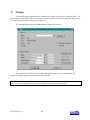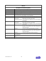
1
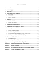
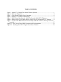
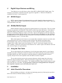
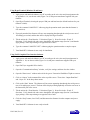
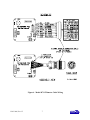
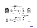
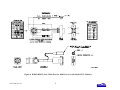
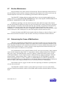
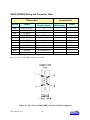
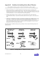
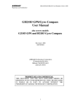
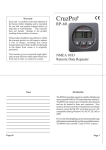
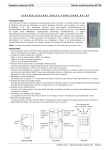
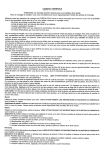
USER’S MANUAL MODEL D711 DIGITAL FLOOR MOUNT TILTMETER (BIAXIAL) Serial No.___________ D711-A High-Gain Version D711-B Mid-Range Version RS232 Output RS485 (RS422) Output 1336 Brommer Street Santa Cruz, CA 95062 USA Tel (831) 462-2801 Fax (831) 462-4418 [email protected] www.geomechanics.com Copyright ©2006 by Applied Geomechanics Inc. All rights reserved. Manual No. B-03-1006, Rev. H TABLE OF CONTENTS 1 Introduction..............................................................................................................................1 2 Technical Highlights ................................................................................................................3 3 Specifications ............................................................................................................................3 4 Digital Output Features and Wiring ......................................................................................4 5 4.1 RS232 Output .....................................................................................................................4 4.2 RS485 (RS422) Output.......................................................................................................4 4.3 Using the Test Cable..........................................................................................................4 Installation ................................................................................................................................4 5.1 Initial Check-Out Procedures ............................................................................................4 5.2 Installing Your Tiltmeter..................................................................................................10 6 Grounding and Transient Protection...................................................................................10 7 Communicating with the Model D711 Tiltmeter ................................................................10 8 7.1 Basic Requirements and Settings .....................................................................................10 7.2 Firmware Command Format ...........................................................................................11 7.3 Firmware Command Summary ........................................................................................12 7.4 Sample Data Using the XY Command .............................................................................13 7.5 Recording Data in Internal Memory or on a PC; Data File Sizes ..................................15 7.6 Switching between RS232 and RS485 (RS422) Output....................................................15 Maintenance and Troubleshooting.......................................................................................15 8.1 Routine Maintenance .......................................................................................................16 8.2 Determining the Cause of Malfunctions ..........................................................................16 Appendix A Custom Specifications for Your Digital Tiltmeter..........................................18 Appendix B Guidelines for Installing Surface Mount Tiltmeters.......................................20 Appendix C Firmware Commands........................................................................................21 Appendix D ZAGI Graphical Interface Software: Installation and Operation ...............33 Appendix E Warranty and Limitation of Liability..............................................................44 TABLE OF FIGURES Figure 1. Model D711 Digital Floor Mount Tiltmeter (Biaxial) ......................................................1 Figure 2. Tiltmeter Dimensions ........................................................................................................2 Figure 3. Floor Mount Tiltmeter Sign Convention...........................................................................6 Figure 4. Model D711 Tiltmeter Cable Wiring ................................................................................7 Figure 5. RS232 Test Cable (Part No. 89063) for Use with Model D711 Tiltmeter........................8 Figure 6. RS485 (RS422) Test Cable (Part No. 89062) for Use with Model D711 Tiltmeter .........9 Figure 7. Layout of the IRIS Printed Circuit Assembly inside the Tiltmeter, Showing Connector Locations..................................................................................................................................17 Figure A1. Face View of Female DB9 Connector with Pin Assignments.........................................19 Figure B1. Installing Model D711 Digital Floor Mount Tiltmeter.................................................20 1 Introduction Model D711 is a precision biaxial digital tiltmeter packaged in a weatherproof housing (Figure 1). It was formerly called Model D711-2(4X). The high-gain version, Model D711-A, has the greatest sensitivity and an angular range of ±0.5 degree. The mid-range version, Model D711-B, has a much greater angular range (±5 degrees) but is less sensitive. Specifications for each version are in Section 3. Some typical applications include precise alignment of telescopes, antennae, and airframes; monitoring of structures and foundations; monitoring of volcanoes; and all jobs that call for precision measurements under demanding operating conditions. The tiltmeter is available with either RS232 or RS485 digital output. RS232 is typically limited to cable lengths less than 15 meters (49.2 feet). The RS485 output of the tiltmeter, which is functionally equivalent to RS422 output, can drive cable lengths greater than 1000 meters (3,231 feet). Your tiltmeter was shipped with the output protocol shown on the title page and in Appendix A. To switch between RS232 and RS485, refer to section 7.6. RS485 multi-drop networks are not currently supported. Model D711 bolts or clamps to any surface and can be used in areas of heavy traffic or vibration. The 12.7-mm (0.5-inch) holes in its three corners (Figure 2) fit over threaded stainless steel studs, provided with each order. The tiltmeter is double-nutted to the studs after they are anchored in the mounting surface (Appendix B). In addition to this user’s manual, the following accessories were shipped with your tiltmeter. Please verify that all are present: Test Cable (RS232 or RS485 Output, P/N 89063 or 89062) Universal Power Transformer for 110 or 220 VAC (P/N 00254-02) Mounting Stud Assembly (P/N 84410) Mating 10-Socket Female Connector (P/N 62401) Acrylic Bubble Level (P/N 00299) ZAGI Graphical User Interface Software (P/N 79104) Quantity 1 1 3 1 1 1 copy Figure 1. Model D711 Digital Floor Mount Tiltmeter (Biaxial) B-03-1006, Rev. H 1 Figure 2. Tiltmeter Dimensions B-03-1006, Rev. H 2 2 Technical Highlights Model D711 includes the following important features: • Tilt angle is measured with an electrolytic sensor, similar to a spirit level. • All electronics reside on a single internal printed-circuit board. • All resistors are premium quality, 1% tolerance, metal-film type. • The tiltmeter comes with a powerful set of user-selectable firmware commands. • All tiltmeters are hand-assembled, calibrated, and tested at our plant under stringent quality control standards. • AGI maintains complete specifications and test records for every tiltmeter built. Your tiltmeter contains two electrolytic level sensors (one for each tilt axis) that produce changes in resistance in response to a rotation of the sensor. A voltage divider network senses the resistance change. The electronics then sample and convert the sensor outputs into tilt angles using factory calibration data stored in nonvolatile memory. The sensors in your tiltmeter measure tilts in two orthogonal vertical planes, X and Y (Figure 3). The vector sum of the outputs of both channels yields the direction and magnitude of rotation with reference to the vertical gravity vector. Please contact us should you require technical assistance when you process your tiltmeter measurements. 3 Specifications General specifications are listed below. Appendix A contains custom specifications for your equipment. Model D711-A High-Gain Version ANGULAR RANGE RESOLUTION REPEATABILITY LINEARITY TIME CONSTANT TEMPERATURE COEF. DIGITAL OUTPUT OUTPUT DATA RATE RS485 TERMINATION POWER REQ’TS ENVIRONMENTAL MOUNTING MATERIALS CABLE SIZE & WEIGHT ±0.5 degree* 1 µradian < 4 µradians (static) 0.4% of full span Model D711-B Mid-Range Version ±5 degrees 10 µradians 10 µradians (static) 0.1% of full span 0.15 second Zero, Kz = ±3.5 µradians/°C typical; Span, Ks = 0.02%/°C typical Two orthogonal tilt angles plus one temperature; RS232 or RS485 (RS422), transmit and receive Baud rate: 9600 (default), 19200, 28800, 57600, 115200, 230400 Formats: NMEA XDR, Trimble proprietary, Ashtech compatible, Simple (x, y, temperature, serial no.) User-selectable from 10 samples/second to 1 sample/24 hours Cable length < 12m: No termination resistors; Cable length > 12m: 100-130Ω termination resistors 7 to 28 VDC @ 27 mA, 250 mV peak-to-peak ripple maximum, reverse polarity protected −25° to +70°C operational, −30° to +100°C storage. Rated NEMA 4X (IP65) for continuous operation at 100% humidity. Withstands exposure to rainfall and spray. Not submersible. Three 0.5-inch (12.7 mm) diameter mounting holes. Tiltmeter fastens to stainless steel mounting studs (included). Anodized and painted aluminum 10 ft (3m) multiconductor cable + overall shield, PVC jacket, connectors included 6 x 6 x 4 inches (152 x 152 x 102 mm), 3 lb (1.4 kg) * 1 degree = 3600 arc seconds = 17453 µradians (microradians) B-03-1006, Rev. H 3 4 Digital Output Features and Wiring Your tiltmeter was set at the factory to have either RS232 or RS485 (RS422) digital output. The setting for your tiltmeter is indicated on the title page and in Appendix A. Firmware commands are summarized in Section 7 and in Appendix C. 4.1 RS232 Output RS232 output is designed for signal transmission over cable lengths less than approximately 15 meters. Figure 4 and Appendix A list the RS232 pin assignments in the tiltmeter cable. Figure 5 shows the wiring of the RS232 test cable. 4.2 RS485 (RS422) Output RS485 and RS422 outputs are designed for signal transmission over long cables. These two output protocols are equivalent in the Model D711and will drive cables longer than 1000 meters. Each tiltmeter with RS485 (RS422) output requires its own serial port. It is not currently possible to operate a series of tiltmeters in “multidrop” fashion on a single 4-wire cable. Figure 4 and Appendix A show the wiring and pin assignments for RS485 (RS422) output. Figure 6 shows the wiring of the RS485 test cable. Wiring of the DB9 connector at one end of the test cable corresponds to the National Instruments 8-port RS485 card for the PCI databus, part no. 777641-08 (2004). When cable length exceeds 12 meters we recommend that termination resistors be used at the ends of the transmit and receive lines to dampen possible reflections and maintain good signal quality. Recommended resistor values are between 100 and 130 Ohms. Connect one resistor between the computer’s Rx+ and Rx- inputs (same as the tiltmeters Tx+ and Tx- wires) at the computer end of the cable. Similarly, connect one resistor between the tiltmeter’s Rx+ and Rx- inputs at the tiltmeter end of the cable. Refer to Figure 6 for pin numbering. 4.3 Using the Test Cable The test cable shipped with your tiltmeter is wired for the same output protocol as your tiltmeter. The RS232 test cable is designed to connect the tiltmeter to the RS232 serial port of a personal computer. The RS485 (RS422) test cable is designed to connect the tiltmeter to an RS485 (RS422) serial port. Typically, this port will be on an expansion card or PCMCIA card in the computer. The test cable includes a power jack (connector) that mates with the output jack of the power transformer shipped with the tiltmeter. When the transformer is plugged into a 110 or 220 VAC wall socket, it supplies 12 Volts DC to the tiltmeter. The standard transformer shipped with the tiltmeter accepts 100 to 240 Volts AC at 50-60 Hz. For safe operation, read the power rating printed on the transformer and verify that it conforms to your wall socket power before use! 5 Installation 5.1 Initial Check-Out Procedures Before installing your tiltmeter, verify that it is functioning properly by following the steps below. Refer to the firmware command summary in Section 7.3. B-03-1006, Rev. H 4 Using HyperTerminal (Windows 95 and later) 1. Apply power and attach the tiltmeter to a PC according to the wire color and pin assignment code in Appendix A. Or, use the test cable (Figure 5 or 6) and power transformer supplied with your tiltmeter. 2. Open HyperTerminal, selecting the proper COM port and baud rate (the default baud rate for your tiltmeter is 9600). 3. Type the command “*9900XYC0” without typing the quotation marks (note that the tiltmeter is case sensitive). 4. If properly attached, the tiltmeter will now start outputting data through the serial port at a rate of 10 readings per second, and the data will be displayed in HyperTerminal. 5. Tilt the unit in the +X and then the +Y direction (Figure 3). Next tilt it in the –X and –Y directions. Verify that the tilt values move through the full angular range (Section 3) and that the sign (polarity) of the output changes on opposite sides of null. 6. Type the command “*9900XYC-OFF” without typing the quotation marks to stop the output. 7. Your Model D711 tiltmeter is now ready for installation. Using ZAGI Graphical User Interface Software 1. Apply power and attach the tiltmeter to a PC according to the wire color and pin assignments in Appendix A. Or, use the test cable (Figure 5 or 6) and power transformer supplied with your tiltmeter. 2. Open ZAGI (see Appendix D for details). 3. Open the “Communications Setup” window, verify the settings, and then close the window. 4. Open the “Data Access” window and wait for the green “Connection Established” light to come on. 5. Click on “Output” in the command line at the top of the screen. Then select “Output Data Rate” and “10 per sec” in the drop-down menus. 6. Click on the “Start” button. The tiltmeter will now start outputting data through the serial port at a rate of 10 readings per second. The data will be displayed both graphically and in the text boxes in the bottom left part of the screen. 7. Tilt the unit in the +X and then the +Y direction (Figure 3). Next tilt it in the –X and –Y directions. Verify that the tilt values move through the full angular range (Section 3) and that the sign (polarity) of the output changes on opposite sides of null. 8. Click the “Stop” button, close ZAGI, and disconnect the tiltmeter from the computer and power supply. 9. Your Model D711 tiltmeter is now ready to install. B-03-1006, Rev. H 5 Figure 3. Floor Mount Tiltmeter Sign Convention B-03-1006, Rev. H 6 Figure 4. Model D711 Tiltmeter Cable Wiring B-03-1006, Rev. H 7 Figure 5. RS232 Test Cable (Part No. 89063) for Use with Model D711 Tiltmeter B-03-1006, Rev. H 8 Figure 6. RS485 (RS422) Test Cable (Part No. 89062) for Use with Model D711 Tiltmeter B-03-1006, Rev. H 9 5.2 Installing Your Tiltmeter Applied Geomechanics Model D711 tiltmeters are designed to be mounted on bolts or studs that are threaded, anchored or cemented into a solid surface (see Appendix B for details). The bolts should be 1/4" to 3/8" (6 to 9 mm) in diameter and extend at least 2" (5.1 cm) above the surface to which the tiltmeter is to be mounted. First, thread a nut onto each stud, positioning it close to the surface. Place a flat washer above each nut. Then place the tiltmeter over the studs, followed by another washer and finally another nut threaded on top of each stud. Then use a small bull’s-eye or carpenter’s level to roughly level the tiltmeter. Perform the final leveling by connecting the tiltmeter to a PC. Use the ZAGI graphical user interface software supplied with your tiltmeter (Appendix D), or the HyperTerminal program included with Microsoft Windows to view the tiltmeter output. Adjust the mounting nuts slowly in sequence (Figure 3) while observing the output to level the tiltmeter. If using HyperTerminal, refer to the firmware commands in Section 7 and Appendix C. It is generally a good idea to install the tiltmeter at the middle of its sensing range, i.e., with the output leveled (nulled) on both channels, so that you will have the maximum dynamic range available for subsequent readings. 6 Grounding and Transient Protection Your tiltmeter has an earth ground circuit that provides protection from high-voltage transients (surges) caused by nearby lightening strikes, unstable power supplies and other sources. High-voltage transients are the most common cause of failure of electronic field instruments. In a typical occurrence, an induced transient from a lightening strike travels along the cable until it encounters the instrument’s electronic circuitry, where the delicate, low-voltage components are overloaded and fail. To help avoid such an occurrence, each tiltmeter input and output circuit is connected to the tiltmeter base plate through variable-resistance type surge absorbers (transzorbs). The transzorbs normally have extremely high resistance. They change to low-resistance conductors when the side connected to the tiltmeter circuitry senses a high voltage, which is then shorted to the metal base plate. To activate this surge protection, you must connect the tiltmeter base plate to earth (e.g. a water pipe or grounding rod) using the earth ground screw location shown in Figure 2. Transient protection and noise reduction can also be enhanced by earthing the cable shield (drain wire) at one end only. Note that the tiltmeter cable shield is not connected to the tiltmeter case or to the circuitry inside the tiltmeter (Figure 4). The transzorbs in the tiltmeter provide a good, basic level of protection, but will not prevent damage under all conditions. If you plan to operate your tiltmeter in an area with frequent lightning storms, we recommend keeping the instrument cable as short as possible. If long cables cannot be avoided, consider adding a commercial lightning protection circuit at one or both ends of your cable. A good source of transient protection products is the Citel company (http://www.citelprotection.com). 7 Communicating with the Model D711 Tiltmeter 7.1 Basic Requirements and Settings You may communicate with the Model D711 tiltmeter using: B-03-1006, Rev. H 10 1. ZAGI Software (supplied with the tiltmeter) and a personal computer running Microsoft Windows; 2. A terminal emulator program (e.g. Terminal in Windows 3.1 or HyperTerminal in Windows 95 and later); or 3. A GPS receiver that is capable of sending and receiving terminal commands. All communication to the tiltmeter is performed through the send (transmit) and receive wires of the serial port. The default parameters for the serial port are set to no parity, 8 bits and 1 stop bit with no hardware or software flow control. The baud rate is the only parameter that is user-selectable. The default baud rate is 9600. Baud rates up to 230400 are supported. 7.2 Firmware Command Format The format of commands issued by the host is: *9900<command><CR><LF> Valid commands are summarized in Section 7.3 and described in detail in Appendix C. The input/output processing on the serial port of the D711 is as follows: (1) Input is read until a <CR> or <LF> (carriage return or line feed) is received. (On a PC, this usually means pressing the ‘Enter’ or ‘Return’ key.) (2) When a line is received, it is parsed to see if it is a command of the device. If it is not, then it is echoed back out, terminated with a <CR> <LF> and we go back to step (1). All strings that are not commands for the unit are echoed. If the command is for the device, we then go to step (3). (3) The command is processed and we return to step (1). All incoming characters are buffered (up to 1000) while the command is being processed. If the command is for ID 99 and echoing of 99 commands is enabled, the command is echoed after the command result is transmitted. Default output of the D711 tiltmeter running firmware version 5 and above is a simple (“SIM”) commadelimited string consisting of X tilt in degrees or microradians, Y tilt in degrees or microradians, temperature in °C, and the serial number of the device. Optional outputs consist of a Trimble Navigation proprietary ASCII string with X (Roll) and Y (Pitch) tilts in degrees, and two output formats that follow NMEA Standard 0183, version 2.1, October 15, 1995. This standard may be obtained from: National Marine Electronics Association (NMEA) National Office P.O. Box 3435 New Bern, NC 28564-3435 USA Tel: 919/638-2626 Fax: 919/638-4885 B-03-1006, Rev. H 11 7.3 Firmware Command Summary The list below summarizes the most important user-accessible firmware commands. Precede these commands with the string *9900. See Appendix C for additional details. XY Outputs a single tilt and temperature measurement. The format of the output depends on the setting of the SO command. SO-xxx Selects the output format for the XY command. “xxx” selects format as follows: ASH: Ashtech compatible NMEA format SIM: Simple x,y,t,sn output string (default) XDR: NMEA XDR format TCM: Trimble Navigation proprietary pitch (Y) and roll (X) string BAE: BAE Systems encoded 11-byte string containing a sync packet, x, y, t, SN, and checksum information. Advanced users only—typically for embedded system integration. XY-MEMS Stores tiltmeter readings at selected output rate in nonvolatile memory. (Versions 5.1 and higher.) XY-MEMD Downloads data from nonvolatile memory. (Versions 5.1 and higher.) XY-M1 Sets the tiltmeter to Mode-1 operation. XYVR Displays the sign-on string. ID Sets the ID of units in the daisy chain (not currently implemented). XY-TR-PASH-ON Translates the Paros provided $PASHS,XDR,P sentences to standard NMEA XDR format. XY-TR-PASH-OFF Turns off translation of $PASHS,XDR,P sentences. XY-EP Enables power on message. XY-SP Disables power on message. XY-EE Enables echoing of global 99 commands. XY-SE Disables echoing of global 99 commands. XY-SET-BAUDRATE,x Sets baud rate to value of x in bits per second. Selectable values include 9600, 19200, 28800, 57600, 115200 and 230400 baud. XY-SET-N-SAMP,x Sets number of samples that are averaged before a reading is transmitted; x may have any value from 1 to 1000. Changing this value may also change the output rate. B-03-1006, Rev. H 12 XY-SET-RSMODE,x Selects serial output mode: x=0 RS232 x=1 RS485 (RS422) XY-AUTOZ Turns on auto zero function. XY-AUTOZOFF Turns off auto zero function. XYCx Continuously sends XY data where x determines output rate as follows: x = 0: x = 1: x = 2: x = 3: x = 4: x = 5: x = 6: x = 7: x = 0A: x = 1A: x = 2A or x = A: 8-10 outputs per second 4 outputs per second 1 output per second (default) 1 output every 10 seconds 1 output every 60 seconds 1 output every hour 1 output every 12 hours 1 output every 24 hours Averaging of the 8-10 outputs per second data Averaging of the 4 outputs per second data Averaging of the 1 output per second data Once initiated, continuous output remains in effect until turned off with the XYC-OFF command (see below). XYC-OFF Turns off XYC mode. XY-DUMP-SETTINGS Dumps settings of device. XY-DUMP2 Dumps extended settings of device. 7.4 Sample Data Using the XY Command The most commonly used command is the XY command, which returns the X and Y tilt angles in degrees or microradians, and the internal temperature of the tiltmeter in ºC. The format of the returned data depends on the setting of the SO command. The returned data are averages of a series of readings. The number of samples used in the average is set by the XY-SET-N-SAMP command. The following lines illustrate the format of the data returned by the XY command for the range of possible SO settings: SO = “ASH.” Ashtech compatible NMEA output string which returns the North-South (Y) and East-West (X) tilt angle in degrees or microradians and the internal temperature of the tiltmeter in ºC: $PASHS,XDR,A,004.261,D,N,A,004.280,D,E,C,021.288,C,T-N1346 $PASHS,XDR,A,004.261,D,N,A,004.280,D,E,C,021.306,C,T-N1346 $PASHS,XDR,A,004.261,D,N,A,004.280,D,E,C,021.298,C,T-N1346 $PASHS,XDR,A,004.261,D,N,A,004.280,D,E,C,021.332,C,T-N1346 B-03-1006, Rev. H 13 SO = “SIM” (default). Simple X,Y,T,SN output which returns the X and Y tilt angle in degrees or microradians and the internal temperature of the tiltmeter in ºC: $-0.619,0.023,18.910,N0000 $-0.619,0.023,18.923,N0000 $-0.620,0.024,18.932,N0000 $-0.620,0.023,18.951,N0000 SO = “XDR.” Standard NMEA XDR output string which returns the North-South (Y) and East-West (X) tilt angle in degrees or microradians and the internal temperature of the tiltmeter in ºC: $YXXDR,A,000.034,D,N,A,-00.625,D,E,C,021.651,C,T-N0000*47 $YXXDR,A,000.034,D,N,A,-00.624,D,E,C,021.675,C,T-N0000*40 $YXXDR,A,000.034,D,N,A,-00.624,D,E,C,021.686,C,T-N0000*4C $YXXDR,A,000.034,D,N,A,-00.625,D,E,C,021.707,C,T-N0000*45 SO = “TCM.” Proprietary Trimble Navigation pitch (Y-tilt) and roll (X-tilt) output string which returns the tilt angle in degrees and a checksum: $P-00.907R002.186*1C $P-00.906R002.183*18 $P-00.908R002.191*15 $P-00.908R002.191*15 $P-00.905R002.190*19 SO = “BAE.” Advanced users only, using the D711-A. BAE Systems encoded 11-byte output which returns two synchronization bytes, the X (2 bytes) and Y (2 bytes) tilt angle, the internal temperature of the tiltmeter (2 bytes), the serial number (2 bytes), and a checksum byte: Uª Ä$é TæUª Ä$ä TáUª Ä$ß TÜUª Ä$é Tæ The BAE output string is not clearly decipherable by HyperTerminal, which sometimes hides characters that it has received and cannot understand. Because of this, it is difficult, if not impossible, to interpret data in this format. The above output string shows four outputs taken from HyperTerminal. The BAE output string is not selectable using ZAGI. This encoded output command is typically used to communicate with embedded systems, as they can view raw data and perform fast translations. The first synchronization byte is 0x55, the second is 0xAA. The X and Y bytes use a scale factor that can be found by issuing the *9900XY-DUMP2<CR> command. This scale factor is in arc seconds per LSB and changes automatically with the range of each instrument (the scale factor is different for the D711-A and D711-B). The temperature uses 0.004 degrees Celsius per LSB. The serial number is a two byte integer. The checksum byte is the result of ANDing bytes 2-7 with 255. BAE output mode reduces the total number of characters per output to 11 bytes, while transferring the same data as the SIM output mode, which requires 33 bytes. BAE mode also includes checksum and frame B-03-1006, Rev. H 14 synchronization bytes. Refer to Appendix C, Firmware Commands, to decode the output. 7.5 Recording Data in Internal Memory or on a PC; Data File Sizes You can log data from your Model D711 tiltmeter in two easy ways: 1. Use ZAGI (Appendix D) to log ASCII data to a storage device on your personal computer. 2. Use the XY-MEMS command or ZAGI to store ASCII data in the tiltmeter’s nonvolatile FLASH memory. The sizes of the data files stored to a PC are approximately: Format ASH SIM XDR TCM 16.5 lines 29.8 lines 16.6 lines 42.3 lines = = = = 1 kilobyte 1 kilobyte 1 kilobyte 1 kilobyte Data stored to FLASH memory must be stored in simple (SIM) format. Approximately 150 lines of data may be stored at any sample rate. Download data using ZAGI or the XY-MEMD command. 7.6 Switching between RS232 and RS485 (RS422) Output You may switch the tiltmeter’s output from RS232 to RS485 (RS422) or back again by issuing the *9900XY-SET-RSMODE firmware command. After switching to RS485, the RS232 test cable (Figure 5) cannot be used to communicate with the tiltmeter. Similarly, after a switch to RS232, the RS485 cable can no longer be used (Figure 6). An additional test cable may be ordered from Applied Geomechanics by specifying P/N 89063 for the RS232 cable or P/N 89062 for the RS485 (RS422) cable. Be sure you have the proper interconnect cable before switching to a new output protocol. Without it, you will lose the ability to communicate with the tiltmeter! 8 Maintenance and Troubleshooting Model D711 Digital Tiltmeters are rugged and require no maintenance other than normal cleaning. Apart from the procedures described below, the tiltmeters are not field-serviceable. If you encounter problems not described here, please contact Applied Geomechanics Inc. at (831) 462-2801 in California. A service engineer will assist you in determining the cause of any problem. B-03-1006, Rev. H 15 8.1 Routine Maintenance Keep all tiltmeters away from extremes of heat and cold. Extreme temperatures shorten the life of the seals and unnecessarily stress the electronic components. Keep tiltmeters out of direct sun because the internal temperature can reach levels considerably greater than the ambient temperature. Your Model D711 tiltmeter has been sealed at the factory to protect it against splashes and wet weather. However, it should NEVER BE SUBMERGED in water or other liquids. WATER DAMAGE TO INTERNAL COMPONENTS VOIDS THE WARRANTY! In addition to providing a seal, the cement between the dome and the base plate of the tiltmeter provides the mechanical bond between these two parts. In normal use the cement will provide a strong and secure attachment. To maximize the bond life and reduce the possibility of separation, lift the tiltmeter by holding the base plate and not the dome. If the dome should separate from the base plate, it can be reattached by: 1) cleaning off the old cement, 2) applying a continuous bead of new silicone rubber cement in the circular groove and 3) holding the two sides firmly together until the cement has cured. Connector locations on the IRIS circuit assembly inside the tiltmeter are shown in Figures 4 and 7. Refer to these locations if the dome is removed and it is necessary to reattach the internal connectors. 8.2 Determining the Cause of Malfunctions Although your Model D711 Digital Tiltmeter is not field-serviceable, there are some basic things you can do if you encounter problems. If there is no output when you have connected the tiltmeter to a PC while using HyperTerminal or ZAGI, check that all connectors are securely attached and properly wired to the power and communication pins. Failure to obtain an output signal from the tiltmeter normally is the result of lack of power or a broken wire or connection. If no communication is seen in HyperTerminal or ZAGI, check your port settings. Most computers connect to their serial ports using COM 1-4. Verify that the software settings conform to the COM port that you are using. The default baud rate of the D711 tiltmeter is 9600 baud, which is factory set and verified upon shipment. If your computer requires a different baud rate, change the tiltmeter’s baud rate setting using the “Communications Setup” window in ZAGI or the XY-SET-BAUDRATE command. Check your wiring (Figures 4, 5 and 6, Appendix A), as RS485(RS422) uses different signals than the single-ended RS232 protocol. For either protocol, verify that the tiltmeter’s transmit output is connected to the receive pin(s) on the computer and that its receive is connected to the PC’s transmit pin(s). If the tiltmeter output is “pegged” at either end of the output range, the tiltmeter is probably tilted off scale. Re-level the unit. Your Model D711 tiltmeter cannot be opened without special tools. If you are certain that the problem is internal to the tiltmeter, contact us for an RMA number and then return the tiltmeter to AGI for repair. B-03-1006, Rev. H 16 WARNING! NEVER USE AN OHMMETER TO MEASURE THE TILT SENSORS INSIDE THE TILTMETER. APPLYING DC CURRENT THROUGH THE SENSORS WILL CAUSE PERMANENT DAMAGE THAT IS NOT COVERED BY THE WARRANTY. Figure 7. Layout of the IRIS Printed Circuit Assembly inside the Tiltmeter, Showing Connector Locations B-03-1006, Rev. H 17 Appendix A Model Number: Custom Specifications for Your Digital Tiltmeter D711-A High-Gain Version D711-B Mid-Range Version Serial Number: ________________ RS232 Digital Output Protocol: Output Units: Degrees Circular Connector on Tiltmeter Cable: Mating In-Line Connector: RS485 (RS422) Microradians AGI P/N 62402, Bendix P/N PT06A-12-10PW(SR) AGI P/N 62404, Bendix P/N PT01A-12-10SW(SR) RS232 Wiring and Connector Table Tiltmeter End Wire Color Function Red Black Power (7V to 28V) Power Ground Transmit Data, TX (RS232) Receive Data, RX (RS232) TX+ (RS485) Blue Green Orange Gray Yellow Brown Drain Wire White Violet TX− (RS485) RX− (RS485) RX+ (RS485) Cable Shield Not used Not used Computer End Pin (Circular Connector) Pin (DB9 Connector) Function H A 5 Ground E 2 Receive Data (RX) G 3 Transmit Data (TX) D J C B F No Connection (NC) NC Pins 4 and 6 in the DB9 connector are shorted. Pins 7 and 8 in the DB9 connector are shorted. Pins 1 and 9 are not used. B-03-1006, Rev. H 18 RS485 (RS422) Wiring and Connector Table Tiltmeter End Wire Color Function Red Black Blue Green Orange Gray Yellow Brown Drain Wire White Violet Power (7V to 28V) Power Ground TX (RS232) RX (RS232) TX+ (RS485) TX− (RS485) RX− (RS485) RX+ (RS485) Cable Shield Not used Not used Computer End Pin (Circular Connector) H A E G D J C B F No Connection (NC) NC Pin (DB9 Connector) Function 1 Ground 4 5 9 8 RX+ RX− TX− TX+ Pins 2, 3, 6 and 7 in the DB9 connector are not used. Figure A1. Face View of Female DB9 Connector with Pin Assignments B-03-1006, Rev. H 19 Appendix B Guidelines for Installing Surface Mount Tiltmeters These guidelines will help you achieve stable and reliable tiltmeter readings. Applied Geomechanics supplies all of the installation accessories you need for an effective monitoring program. • Surface mount tiltmeters are typically attached to the measurement surface by mounting studs (threaded rods) fastened or anchored into the surface. Three-point mounting is best because it prevents bending and torsion that can lead to unstable readings. Single-stud (monopod) mounting is more prone to drift and disturbance. It is not recommended for long-term applications. • Mounting studs should be as short as possible, of the same length and of the same material for maximum thermal stability. In special cases thermally stable, but more expensive, invar studs can be used. • Anchoring a mounting stud in a concrete or rock surface is normally done by drilling a hole to a depth of 4-5 cm (1 ½ - 2 inches), then injecting a small amount of anchoring epoxy. When the stud is inserted into the hole, the epoxy squeezes to the top, surrounding the embedded part of the stud. Lead anchors and expanding anchors can also be used, but only if the mounting plate or bracket is drawn tight against the surface and cannot shift laterally. Figure B1 illustrates installation techniques for your tiltmeter. Please contact AGI with questions or for additional details. Figure B1. Installing Model D711 Digital Floor Mount Tiltmeter B-03-1006, Rev. H 20 Appendix C B-03-1006, Rev. H Firmware Commands 21 Firmware Commands Valid commands are listed below. Some commands have more than one string to trigger the command. “tt” stands for the target ID (99) and “ss” stands for the source ID (00). Settings stored in nonvolatile memory remain in effect until disabled, even after a power cycle. --------------------------------------XY Outputs a single tilt measurement. The format of the output depends on the setting of the SO command. Syntax: *ttssXY<CR><LF> Error Strings: None. Default: N/A Persistence: N/A Example: command: *9900XY<CR><LF> response: $YXXDR,A,-00.920,D,N,A,-00.210,D,E,C,030.045,C,T-N1212*57 --------------------------------------SO Selects the output format for the XY command. are: The possible formats -SIM $x.x,y.y,t.t,sn<CR><LF> | | | | | | | Serial number | | Temperature of tiltmeter | Y-tilt value in degrees or microradians (see Appendix A) X-tilt value in degrees or microradians (see Appendix A) Example: $-00.920,-00.210,030.045,N1212 -XDR $YXXDR,A,x.x,D,N,A,x.x,D,E,C,x.x,C,T-sn*hh<CR><LF> | | | | | | | | | | | | | | | | | | | | | | | | | | | Checksum | | | | | | | | | | | | Serial number | | | | | | | | | | | Comment, T for temperature | | | | | | | | | | Units, C=degrees C | | | | | | | | | Temperature of tiltmeter | | | | | | | | Data Type, C=Temperature | | | | | | | Comment, E for East/West (X) direction | | | | | | Units, M=microradians, D=degrees | | | | | X (E)-tilt value | | | | Data Type, A=Angular | | | Comment, N for North/South (Y) direction | | Units, M=microradians, D=degrees, | Y (N)-tilt value Data Type, A=Angular Example: $YXXDR,A,-00.920,D,N,A,-00.210,D,E,C,030.045,C,T-N1212*57 B-03-1006, Rev. H 22 -ASH $PASHS,XDR,A,x.x,D,N,A,x.x,D,E,C,x.x,C,T-sn<CR><LF> | | | | | | | | | | | | | | | | | | | | | | | | | Serial number | | | | | | | | | | | Comment, T for temperature | | | | | | | | | | Units, C=degrees C | | | | | | | | | Temperature of tiltmeter | | | | | | | | Data Type, C=Temperature | | | | | | | Comment, E for East/West direction | | | | | | Units, M=microradians, D=degrees | | | | | X (E)-tilt value | | | | Data Type, A=Angular | | | Comment, N for North/South direction | | Units, M=microradians, D=degrees | Y (N)-tilt value Data Type, A=Angular Example: $PASH,XDR,A,-00.920,D,N,A,-00.210,D,E,C,030.045,C,T-N1212 -TCM $Py.y,Rx.x*hh<CR><LF> | | | | | | | | CheckSum | Roll= X-tilt value in degrees Pitch= Y-tilt value in degrees Example: $P-00.905R002.190*19 -BAE abcdefghijk ||||||||||| ||||||||||Byte 10(k): Checksum of bytes 2-7 ANDed with decimal 255 |||||||||| ||||||||Byte 8-9(i,j): Serial number in hexadecimal format |||||||| ||||||Byte 6-7(g,h): Temperature in Deg. C. Bits 14 – 0 = magnitude |||||| (LSB bit = 0.004 Deg. C.), Bit 15 = sign |||||| ||||Byte 4-5(e,f): Y Axis Level Data. Bits 14 – 0 = magnitude |||| (LSB bit scale factor found in XY-DUMP2), Bit 15 = sign |||| ||Byte 2-3(c,d): X Axis Level Data. Bits 14 – 0 = magnitude || (LSB bit scale factor found in XY-DUMP2), Bit 15 = sign || |Byte 1(b): 0xAA, 2nd Synchronization Byte | Byte 0(a): 0x55, 1st Synchronization Byte B-03-1006, Rev. H 23 Syntax: *ttssSO-<output format><CR><LF> Error Strings: ERR XY-SO BAD PARAMETER <output format> was invalid. ERR XY-SO PARSE ERROR Could not parse <output format>. Default: SIM Persistence: Setting is stored in nonvolatile memory. Example: command: *9900SO-XDR<CR><LF> response: <none> --------------------------------------XY-MEMS Stores the tiltmeter readings in simple format (SO-SIM) at selected output rate in nonvolatile memory. Syntax: *ttssXY-MEMS<CR><LF> Error Strings: None. Default: N/A Persistence: Subsequent tiltmeter readings stored in nonvolatile memory until memory is full. Maximum of approximately 150 lines of data. Example: command: *9900XY-MEMS<CR><LF> response: <none> --------------------------------------XY-MEMD Downloads the tiltmeter readings in nonvolatile memory to PC. Syntax: *ttssXY-MEMD<CR><LF> Error Strings: None. Default: N/A Persistence: Stored tiltmeter readings downloaded at rate of 1 per second to PC in ASCII comma-delimited string. Example: command: *9900XY-MEMD<CR><LF> response: $start:11-11-1997 18:43:09 4/sec $000.699,-01.022,025.116,N1028 $000.699,-01.022,025.116,N1028 $000.698,-01.021,025.110,N1028 $000.698,-01.022,025.122,N1028 B-03-1006, Rev. H 24 --------------------------------------XY-M1 Sets the operation to Mode 1. This command groups several other commands together for convenience. The commands that are issued are: XY-TR-PASH-ON XY-SO-XDR XY-SE XY-SP Syntax: *ttssXY-M1<CR><LF> Error Strings: None. Default: N/A Persistence: Setting is stored in nonvolatile memory. Example: command: *9900XY-M1<CR><LF> response: AGI Model D711-A Firmware V2.2 SN-N1212 ID01 --------------------------------------XYVR Displays the sign-on string. Syntax: *ttssXYVR<CR><LF> Error Strings: None. Default: N/A Persistence: N/A Example: command: *9900XYVR<CR><LF> response: AGI Model D711-A Firmware V5.2 SN-N1212 ID01 --------------------------------------ID This command is not currently supported. Sets the ID of units in the daisy chain. The first device in the serial chain sets its ID to the source ID plus one (ss+1), and then outputs a the ID command to the next device with the source ID set to its new ID. The target ID of this command must be 99. Syntax: *99ssID<CR><LF> Error Strings: None. Default: 01 Persistence: Setting is stored in nonvolatile memory. Example: command: *9900ID<CR><LF> response: *9901ID<CR><LF> B-03-1006, Rev. H 25 --------------------------------------XY-TR-PASH-ON Translates the Paros provided $PASHS,XDR,P sentences to standard NMEA XDR format. An example input PASH string would be: $PASHS,XDR,P,1.000123,B,SN123,C,22.12,C,SN123,H,32.11,P,SN123<CR><LF> The translated string would then be: $WIXDR,P,1.000123,B,SN123,C,22.12,C,SN123,H,32.11,P,SN123*hh<CR><LF> Syntax: *ttssXY-TR-PASH-ON<CR><LF> Error Strings: None. Default: Off. Persistence: Setting is stored in nonvolatile memory. Example: command: *9900XY-TR-PASH-ON<CR><LF> response: <none> --------------------------------------XY-TR-PASH-OFF Turns off translation of $PASHS,XDR,P sentences. Syntax: *ttssXY-TR-PASH-OFF<CR><LF> Error Strings: None. Default: N/A Persistence: Setting is stored in nonvolatile memory. Example: command: *9900XY-TR-PASH-OFF<CR><LF> response: <none> --------------------------------------XY-EP Enables power on message. Power on message is: AGI Tiltmeter Firmware V5.2 SN-N1212 ID01 Where V5.2 is the firmware version, SN-N1212 is the serial number of the device and ID01 is the target's ID. Syntax: *ttssXY-EP<CR><LF> Error Strings: None. Default: On. Persistence: Setting is stored in nonvolatile memory. Example: command: *0100XY-EP<CR><LF> response: <none> B-03-1006, Rev. H 26 --------------------------------------XY-SP Disables power on message. Syntax: *ttssXY-SP<CR><LF> Error Strings: None. Default: N/A Persistence: Setting is stored in nonvolatile memory. Example: command: *9900TR-SP<CR><LF> response: <none> --------------------------------------XY-EE Enables echoing of global 99 commands. If the unit receives a command for ID 99, then the unit will respond to the command and echo the command when it is done. Syntax: *ttssXY-EE<CR><LF> Error Strings: None. Default: On. Persistence: Setting is stored in nonvolatile memory. Example: command: *0100XY-EE<CR><LF> response: <none> --------------------------------------XY-SE Disables echoing of global 99 commands. If the unit receives a command for ID 99, then the unit will respond, but the unit will NOT echo the command when it is done. Syntax: *ttssXY-SE<CR><LF> Error Strings: None. Default: N/A Persistence: Setting is stored in nonvolatile memory. Example: command: *0100XY-SE<CR><LF> response: <none> B-03-1006, Rev. H 27 --------------------------------------XY-SET-BAUDRATE,x Changes communications baud rate. Maximum supported baud rate is 57,600 baud. The parameter x is an integer with up to six places, defining the baud rate as follows: 9600 19200 28800 57600 115200 230400 = = = = = = 9600 baud 19200 baud 28800 baud 57600 baud 115200 baud 230400 baud Syntax: *ttssXY-SET-BAUDRATE,x<CR><LF> Error Strings: ERR XY-SET-BAUDRATE,x PARSE ERROR. Default: 9600 Persistence: Setting is stored in nonvolatile memory. Example: command: *9900XY-SET-BAUDRATE,57600<CR><LF> response: <none> --------------------------------------XY-SET-N-SAMP,x Sets the number of samples that are averaged before a reading is transmitted. The parameter x is an integer between 1 and 1000 equal to the number of samples that are averaged. Syntax: *ttssXY-SET-N-SAMP,x<CR><LF> Error Strings: None. Default: Depends on data output rate, as specified by the XYCx command. The default numbers of samples averaged for each data rate are: XYC0: XYC1: XYC2: XYC3: XYC4: XYC5: XYC6: XYC7: 28 100 460 500 500 500 500 500 If the number of samples specified exceeds the number listed above for XYC0, XYC1 or XYC2, the microprocessor reduces the data output rate until it has enough time to collect and average all of the samples. Persistence: Once initiated, the same averaging remains in effect even with power cycle. (Setting is stored in nonvolatile memory.) Can be changed by reissuing the command with a different value for x, or by changing the output rate with the XYCx command. Example: command: *9900XY-SET-N-SAMP,250<CR><LF> response: <none> B-03-1006, Rev. H 28 --------------------------------------XY-SET-RSMODE,x Sets output protocol to RS232 or RS485(RS422), as follows: x = 0: RS232 x = 1: RS485(RS422) Syntax: *ttss XY-SET-RSMODE,x<CR><LF> Error Strings: None. Default: Set in factory to customer specification. Persistence: Once initiated, remains in effect even with power cycle. (Setting is stored in nonvolatile memory.) Example: command: *9900XY-SET-RSMODE,0<CR><LF> response: <none> CAUTION: If you change the output protocol, you will no longer be able to communicate with the tiltmeter unless you have the correct interconnect cable. --------------------------------------XY-AUTOZ Turns autozero function on, causing tiltmeter to subtract current X and Y readings from all subsequent X and Y readings. Syntax: *ttssXY-AUTOZ <CR><LF> Error Strings: None. Default: Off. Persistence: Setting is stored in nonvolatile memory. Example: command: *9900XY-AUTOZ<CR><LF> response: <none> --------------------------------------XY-AUTOZOFF Turns autozero function off, causing tiltmeter to display non-biased (unshifted) position readings. Syntax: *ttssXY-AUTOZ-OFF<CR><LF> Error Strings: None. Default: Off. Persistence: Setting is stored in nonvolatile memory. Example: command: *9900XY-AUTOZ-OFF<CR><LF> response: <none> B-03-1006, Rev. H 29 -------------------------------------XYCx Continuously sends XY data - even after power has been turned off and then on again. Timing is determined by the microprocessor’s crystal and is approximate. The parameter x is an integer between 1 and 7, the letter A, or 0A, 1A, or 2A. An A indicates the use of the moving average function, in which the moving average of the data is output. When the moving average function is used, the first output is delayed until the first n readings have been taken, where n is the number of readings to be averaged. After that, the outputs occur at the same rate as the readings. For example, the command XYC2A outputs the moving average of the same data that would be output if the user issued the command XYC2. Since XYC2 outputs data once per second, XYC2A also outputs once per second. However, the first output occurs after a four-second delay, in which the first four readings (at a rate of 1 per second) are averaged. The second output is the average of readings 2-5, the third output is the average of readings 3-6, and so on, creating an output rate equal to that of XYC2. The parameter x determines rate of continuous output as follows: x = 0: 1: 2: 3: 4: 5: 6: 7: 0A: 1A: 2A or A: 8-10 per second 4 per second 1 per second 1 every 10 seconds 1 every 60 seconds 1 every 60 minutes 1 every 12 hours 1 every 24 hours Average of 8-10 outputs/sec data. 10 readings are averaged. Average of 4 outputs/second data. 4 readings are averaged. Average of 1 output/second data. 4 readings are averaged. Syntax: *ttssXYCx<CR><LF> Error Strings: None. Default: Off. Persistence: Once initiated, continuous output remains in effect even with power cycle. (Setting is stored in nonvolatile memory.) Must be turned off using the XYC-OFF command (see below). Example (with SO=”SIM”): command: *9900XYC1<CR><LF> response: $-00.699,000.070,020.290,N0000 $-00.699,000.071,020.309,N0000 $-00.699,000.071,020.313,N0000 $-00.699,000.071,020.330,N0000 $-00.699,000.071,020.348,N0000 $-00.700,000.070,020.360,N0000 B-03-1006, Rev. H 30 --------------------------------------XYC-OFF Turns off XYC mode. Syntax: *ttssXYC-OFF<CR><LF> Error Strings: None. Default: N/A. Persistence: Setting is stored in nonvolatile memory. Example: command: *0100XYC-OFF<CR><LF> response: *0100XYC-OFF<CR><LF> --------------------------------------XY-DUMP-SETTINGS Dumps settings of device. Syntax: *ttssXY-DUMP-SETTINGS<CR><LF> Error Strings: None. Default: N/A Persistence: N/A Example: command: *9900XY-DUMP-SETTINGS response: APPLIED GEOMECHANICS Tiltmeter Firmware V5.0 SN-N2144 ID01 01: Vbias= 2047.000000000 2047.000000000 NaN NaN 01: Vgain= 0.005000000 0.005000000 0.000610350 0.000610350 01: Vmin: -2.50 -2.50 2.50 2.50 01: Vmax: 2.50 2.50 2.50 2.50 01: a0= 0.00000 0.00000 0.00000 0.00000 0.00000 0.00000 01: a1= 0.00000 0.00000 0.00000 0.00000 0.00000 0.00000 01: a2= 0.00000 0.00000 0.00000 0.00000 0.00000 0.00000 01: a3= 0.00000 0.00000 0.00000 0.00000 0.00000 0.00000 01: Tcoef 0: Ks= 0.0003 Kz= 0 Tcal= 25 01: Tcoef 1: Ks= 0.0003 Kz= 0 Tcal= 25 01: N_SAMP=1000 Xzero= 0.00 Yzero= 0.00 01: TR-PASH-OFF E99-ON SO-NMEA-SIM XY-EP 9600 baud FV- B-03-1006, Rev. H 31 --------------------------------------XY-DUMP2 Dumps extended settings of device. Syntax: *ttssXY-DUMP2<CR><LF> Error Strings: None. Default: N/A Persistence: N/A Example: command: *9900XY-DUMP2 response: 01: TBias: 6.86 Above 0.00(KZMinTemp): kz[0]= 0, kz[1]= 0 Below 0.00(KZMinTemp): kz[2]= 0, kz[3]= 0 01: ADCDelay: 310 01: PCA Model: 84833-04 01: Firmware Version: 5.2 Rev G 01: X Ch Gain= 1.0000, Y Ch Gain= 1.0000, Temperature Gain= 1.0000 01: Output Mode: ArcSeconds 01: Calibration performed in Degrees 01: Control: On 01: Using RS232 01: Real Time Clock: Not Installed 01: Use RTC for Timing: No 01: External Flash Capacity: 0 Bytes(Not Installed) 01: Relay Thresholds: 01: Xpositive= 1.0000 Xnegative=-1.0000 01: Ypositive= 1.0000 Ynegative=-1.0000 01: Relay Hysteresis: 01: Hysteresis= 0.0000 01: Calibration method: Dynamic 01: Positive Limit= 0.53 Negative Limit=-0.53 01: Calibration Points:025 X: Enabled Y: Enabled 01: Uniaxial (x2) Sensor Type (1) 01: ADC: 12-bit (internal) 01: DAC Output Scale Factor: 4.76 Volts/Degree 01: Total Sample Storage Capacity: 372 01: BAE Scale Factor: 0.05768 (arcseconds/bit) B-03-1006, Rev. H 32 Appendix D B-03-1006, Rev. H ZAGI Graphical Interface Software: Installation and Operation 33 1 Introduction ZAGI software has been specially designed to work with AGI’s digital clinometers and tiltmeters. ZAGI runs on PCs with Windows 95 and later editions of the Microsoft Windows operating system. It offers an easy-to-use interface for a single tiltmeter connected to a PC serial port. Graphical strip charts display X and Y tilts and numerical displays show X and Y tilts and temperature. The output rate of the instrument and the output string format can be changed using on-screen toggles. Some additional features include autozero, selectable baud rates, and a search feature for finding the baud rate of the clinometer. ZAGI will store instrument output in a file for later plotting and manipulation in ZAGI or in other programs such as AGI’s TBASE II program or spreadsheet programs such as EXCEL. 2 System Requirements ZAGI combines data logging capabilities with configuring, downloading, and displaying of data from AGI’s digital clinometers. The performance of the graphical data displayed on your PC is dependent on the ability of the operating system to acquire, parse and distribute the data to the display. For best performance we recommend that this software be installed on a PC with a 100 MHz or faster Pentium processor and at least 24 megabytes of RAM. Installation of ZAGI requires approximately 3 megabytes of free disk space. 3 Installing ZAGI While running Windows, insert Disk 1 of the ZAGI installation disks and run A:Setup.exe (where A: is the drive specification where the installation disk resides). Follow the instructions on the screen. The program by default will be installed in “C:\ZagiXX,” where XX is the version of the ZAGI program. If you desire, you can change the default directory. B-03-1006, Rev. H 34 4 Configuring Communications Once ZAGI is running, the main screen will be displayed. The “Communications Setup” option will be bold, while the “Data Access” option will be grayed out (see above). This indicates that the user must enter the communications setup first. Push the “Communications Setup” button and the following screen will be presented: B-03-1006, Rev. H 35 The parameters which are user selectable on this screen are the Com port and the baud rate. The default Com port is Com 1. Use the mouse to select the Com port that is connected to the digital clinometer. The baud rate of the digital clinometer is programmed into its microprocessor. All digital clinometers are shipped with the baud rate set to 9600 baud. If you haven’t changed the baud rate (user selectable on the “Data Access” screen described below) then no additional changes are necessary. If you have changed the baud rate, move the baud rate slider to the baud rate of the digital clinometer. If you don’t know the baud rate, click on the “Auto Sense Baud Rate” and ZAGI will find the baud rate of the digital clinometer for you. Baud rates slower than 9600 are no longer supported. No other parameters on this screen are user selectable. Now exit this screen and return to the main screen. 5 Data Access After the communications parameters have been configured, click on “Data Access” (which should now be displayed in bold type) to show the data display screen. When entering this screen you should wait about ten seconds for the indicator under “Connection Established” to change from red to green. This means that the connection between the clinometer and computer has been established. If the green indicator does not come on, exit this screen and re-enter the “Communications Set-up” screen to verify that your settings are correct. (In rare instances the Com port may “hang.” This requires that you exit the ZAGI program and then re-enter it to acquire the Com port.) B-03-1006, Rev. H 36 Most of the commands on the display screen are associated with firmware commands discussed in Appendix C—Firmware Commands. A description of the menu and screen options is summarized in the next section. 6 Command Line Menu Options Output - Selects output ASCII string format Output String Format - The following string formats are supported: • ASH: Ashtech compatible NMEA string • SIM: Simplified format • XDR: Standard NMEA XDR string • TCM: Trimble Navigation proprietary pitch and roll output • LCD: For use with LCD display only (firmware version 2.4r only) Reset Baud Rate - Drop down list of available baud rates. Once changed, “Communications Setup Screen” must be re-entered to reestablish communication. • 2400 baud (not supported) • 3600 baud (not supported) • 4800 baud (not supported) • 9600 baud • 19200 baud • 57600 baud Output Data Rate - Change rate of continuous output from clinometer. • 10 per second • 4 per second • 1 per second • 1 per 10 seconds • 1 per 60 seconds • 1 per hour • 1 per 12 hours • 1 per 24 hours Plots - Selects options and files for plotting and saving. Axis Limits: Plot Saved File: Save Event to File: Allows user-selected axis limits for real-time plotting or plotting of saved files. Selects saved data file for plotting. All saved data files have *.dat extension. This feature only works when not recording data. Saves event plotted on graph to *.dat file. Memory Options - Activates storing and retrieving readings from non-volatile memory. Log Data: Download Data: B-03-1006, Rev. H Continuous output from instrument is written to non-volatile memory when “Start” is pressed. A maximum of 319 stored readings is supported. Screen plotting is not available while logging data. Retrieves stored data from instrument when “Start” is pressed. Data is stored in *.dat file (the “Save to file” option is automatically selected). 37 Dump Settings - Writes stored settings of instrument to file “tiltset.txt”. Print Screen! - Prints image of screen to system printer. 7 Screen Options Connection Established - Communication between clinometer and PC established. The indicator must be green for data recording to operate properly. Memory Log/Download - Indicator turns green when logging or retrieving logged data. Event Markers - Activates and displays events. The yellow “EM” button is used to mark an event. Each event is denoted by line color on the strip chart, and by a number appended to each line in the (optionally) saved *.dat file. The “EM” button is also used to plot the entire stored file. Auto Zero - Subtracts current X, Y readings from subsequent readings. Save to file - Saves data being plotted or downloaded to user-selected *.dat file on your PC (checked box indicates that option is activated). Start - Initiates one of the following three responses from tiltmeter depending on user-selected options: Default: Continuous data output to PC. Data displayed in real time on strip charts. Log Data: Stores continuous output in instrument non-volatile memory. ZAGI will display time to fill memory at current output rate. Green “Memory Log/Download” indicator comes on while logging or downloading. Download Data: Initiates data transfer from tiltmeter to PC. “Download data” screen option is automatically invoked when downloading stored data. Stop – Stops recording data. Exit - Returns to main screen. B-03-1006, Rev. H 38 8 Equivalent Firmware Commands Table D1 below lists the commands issued by ZAGI to the digital tiltmeter. These commands are described in detail in Appendix C. Table D1 Command (Associated Firmware Command) Description Output String Format (SO-xxx) Changes format of output string. Only the simple string format (SO-SIM) is available when storing data in the clinometer’s memory (“Log Data” option selected.) (XY-SET-BAUDRATE-xxxx) Displays a drop-down list of baud rates. Clicking on a baud rate writes that baud rate to the EPROM. A new baud rate should only be selected when the clinometer is not running (before pressing “start” or after pressing “stop”). When a new baud rate is selected, the green indicator will change to red. This means you must go to the “Communications Settings” screen to change the baud rate to correspond with that written to the EPROM. (XYCx) Changes output rate. Fastest rate is 8-10 times per second. Slowest is 1 time every 24 hours. (XY-MEMS) Stores continuous output in the clinometer memory. A maximum of about 150 lines of data can be stored in memory, and only the simple string (X-tilt, Y-tilt, Temperature, Serial Number) is supported when logging data. Data is continuously stored at the output rate selected by the user until memory is full, at which time data logging ceases. The program will tell you how long you can store data at a selected rate when you push “Start.” (XY-MEMD) Retrieves data stored in the clinometer’s memory and plot on screen. The “Save to file” screen option is automatically invoked with this option selected and the “Start” button pushed. (XYCx) Begins operation of clinometer. Based on user selectable options, one of three modes begins when “Start” is pushed. By default, pushing “Start” begins continuous output of the clinometer at userselected rate to the Com port. If “Log Data” has been selected, continuous output from the instrument is stored in the clinometer memory. If “Download Data” is selected, the data stored in the clinometer memory is sent to the PC and shown on the graphical display. (XYC-OFF) Stops current operation of clinometer. (XY-DUMP-SETTINGS) Writes the configuration settings for the digital clinometer in a file called “TILTSET.TXT” (XY-AUTOZ) Subtracts current X- and Y-axis readings from subsequent readings. Reset Baud Rate Data Output Rate Log Data Download Data Start Stop Dump Settings Auto Zero B-03-1006, Rev. H 39 9 Event Markers; Plotting Saved Files Event markers are used to distinguish one part of the time series displayed on the strip chart recorder from another. With the clinometer running, pushing the yellow “EM” button causes the color of the line on the strip chart to change - as shown by the colored boxes below the “EM” button. The default color is always blue. Blue is event “0” and is designated in a saved data set with a zero at the end of the delimited string. When the “EM” button is pushed for the first time, the line color on the graph changes from blue to red, and the data is appended with the number 1. The red box with the number one in it also changes to bright red, indicating that event 1 is presently being plotted. These colors and numerals indicate the event color plotted on the strip chart. Pressing these while plotting a saved file plots the event on the strip chart. Press EM to change events - or to plot an entire saved data file. The Event Marker buttons are also used to plot data that have been saved to a file on your PC. After choosing to plot a saved data file from the command line menu options (Plots > Plot Saved File), pushing the “EM” button plots the entire time series. Pressing any one of the active individual event markers plots only that event. 10 Data Logging to Tiltmeter Memory AGI digital tiltmeters running firmware version 2.3 or later have the capability to store approximately 150 lines of data in the instrument’s FLASH memory. This memory is nonvolatile and will be retained when power to the instrument is turned off or disconnected. It is important to keep in mind the following conditions when using the logging capability: 1. Only the simple string format is supported for data logging operations. 2. Select the simple (SIM) string format and the desired output rate before starting the instrument in logging mode. 3. To log data, click on “Memory Options” and then “Log Data.” Next, click on the “Start” button. 4. There will be a 3-4 second delay after the “Start” button is pushed. Then the program will tell you how long the tiltmeter will be able to store readings in its memory. Click “OK” to begin logging. 5. After the buffer is filled, the instrument will stop logging, but it does not shut down. The readings will continue to be taken at the predetermined sample rate and then sent out the serial port of the instrument. 6. After logging begins, the computer can be disconnected from the tiltmeter, but power must be continuously supplied to the instrument. 7. In the event of a power interruption, the tiltmeter will stop saving measurements. However, all measurements up to the power interruption will be retained in memory. 8. Re-establishing communications with the device by using ZAGI will turn off the logging. B-03-1006, Rev. H 40 9. To plot the data retained in the tiltmeter using ZAGI, you must first download the data to a file on your PC. Select “Download Data” from the “Memory Options” menu item and push the “Start” button. ZAGI will then ask you to specify a file name for the downloaded data. If the data file name chosen already exists, the program will ask whether you want to rename or overwrite the existing file. After you have made your selection, the program will write the data to your PC. 10. You are now ready to plot the retrieved data on the X and Y graphs of the ZAGI screen. Click on “Plots” in the command line, and then “Plot Saved File.” Then, select the file using the window that pops up and click “OK.” Finally, click on the “EM” button or on the “0” event marker button to plot the entire file. Note: Event markers are not operational when logging data to the tiltmeter memory. 11 Data File Format Data output from the clinometer with a simple string format is a comma-delimited ASCII file with the following format (assuming simple string format): X-Tilt, Y-Tilt, Temperature (°C), Serial No., Event Marker Each line represents one measurement. The time interval between measurements equals the data output rate of the clinometer: $0.500,0.458,28.201,N0000,1 $0.500,0.458,28.189,N0000,1 $0.500,0.458,28.189,N0000,1 When data are being acquired and saved to a file only (not logged), the data output interval is not recorded. It therefore must be remembered by the user for future processing. When the data are retrieved from the clinometer’s memory (data logging mode), the date, starting time and output rate are stored in the first line of the output file as shown below: $start:07-07-1997 10:25:40 4/sec $0.500,0.458,28.176,N0000,0 $0.500,0.458,28.176,N0000,0 $0.500,0.458,28.174,N0000,0 $0.500,0.458,28.186,N0000,0 $0.500,0.458,28.187,N0000,0 $0.500,0.458,28.189,N0000,0 $0.500,0.458,28.192,N0000,0 $0.500,0.458,28.188,N0000,0 $0.500,0.458,28.189,N0000,0 $0.500,0.458,28.189,N0000,0 The data above represent 10 records collected at a rate of 4 per second for a total elapsed time of 2.5 seconds. Because event markers are not operational when logging data to the tiltmeter memory, an event marker of “0” is appended to each line of data. B-03-1006, Rev. H 41 12 Printing Executing the print command prints a modified screen image, in either color or black & white. The printed image is modified from the screen image by removing several of the screen items that don’t provide any useful information and would just clutter the print. The following figure shows the “Print Screen!” window for reference: Choosing the correct options for your printer generally requires some experimentation. The options on the print options screen are discussed in Table D2. CAUTION: The “Use Bitmap Printing” may cause your system to lock-up. This option was designed for older style printers and does not work with most printers available on the market today. B-03-1006, Rev. H 42 Table D2 Description of Print Screen! Options Parameter Name Properties Type Where Eject page after printing Print to file Width Height Horizontal offset Vertical offset Force black & white Visible area only Use Bitmap printing B-03-1006, Rev. H Options Displays currently selected printer; allows new selection to be made Allows user to select print properties such as paper size, number of copies, etc. Displays Windows printer Displays port selection Unchecking this box causes the print to be held in the memory of a laser printer. This can be used to overlay images on top of each other. Save image to binary file. This file can be used by some high-end printers. Millimeter/10 Paper width in tenths of a millimeter Entire Paper Print image to fill entire paper width Proportional to height Forces the hard copy width to be to be scaled integrally to the height. Millimeter/10 Paper height in tenths of a millimeter Entire Paper Print image to fill entire paper height Proportional to width Forces the hard copy height to be to be scaled integrally to the width Millimeter/10 Sets the horizontal (x) offset of the hard copy image on the paper. The coordinates (0,0) define the upper left corner of the paper. Centered Centers the image in the horizontal (x) direction Millimeter/10 Sets the vertical (y) offset of the hard copy image on the paper. The coordinates (0,0) define the upper left corner of the paper. Centered Centers the image in the vertical (y) direction Checking this box forces the printer to print in black & white, disregarding color information. Checking this box causes the window frame and menu bar to be added to the print. Not functional at this time 43 Appendix E Warranty and Limitation of Liability Standard goods (those listed in Applied Geomechanics’ published sales literature, excluding software) manufactured by Applied Geomechanics Inc. (AGI) are warranted against defects in materials and workmanship for twelve (12) months from the date of shipment from AGI’s premises with the following exceptions: Series 900 analog or digital clinometers are warranted against defects in materials and workmanship for 90 days from the delivery date. AGI will repair or replace (at its option) goods that prove to be defective during the warranty period provided that they are returned prepaid to AGI and: (a) that the goods were used at all times for the purpose for which they were designed and in accordance with any instructions given by AGI in respect of them, (b) that notice is received by AGI within 30 days of the defects becoming apparent, and (c) that return authorization is received from AGI prior to the goods being sent back. Should goods be damaged in transit to the Purchaser, AGI will accept no liability unless the Purchaser can show that such damage arose solely from AGI’s failure to pack the goods properly for shipment. Software products are warranted to perform substantially in accordance with their documentation for 90 days following your receipt of the software. AGI and its suppliers do not and cannot warrant the performance or results you may obtain by using the software or its documentation. In respect of goods or parts thereof manufactured by others and resold by AGI, AGI will pass on to the customer the benefit of any guarantee or warranty received by AGI from the original manufacturer insofar as such guarantee or warranty is assignable. ANY OTHER CONDITIONS OR WARRANTIES WHETHER EXPRESS OR IMPLIED BY STATUTE OR OTHERWISE ARE EXCLUDED. THE REMEDIES PROVIDED HEREIN ARE THE BUYER’S SOLE AND EXCLUSIVE REMEDIES. APPLIED GEOMECHANICS INC. SHALL NOT BE LIABLE FOR ANY DIRECT, INDIRECT, SPECIAL, INCIDENTAL OR CONSEQUENTIAL DAMAGES, INCLUDING LOST PROFITS OR LOST SAVINGS, WHETHER BASED ON CONTRACT, TORT, OR ANY OTHER LEGAL THEORY. THIS WARRANTY EXTENDS ONLY TO THE ORIGINAL PURCHASER AND IS EXPRESSLY IN LIEU OF ALL OTHER WARRANTIES, WHETHER OF MERCHANTABILITY OR FITNESS FOR ANY PARTICULAR USE, AND OF ALL OTHER OBLIGATIONS AND LIABILITIES OF ANY KIND AND CHARACTER. THERE ARE NO WARRANTIES WHICH EXTEND BEYOND THE DESCRIPTION ON THE FACE HEREOF. AGI’s liability arising out of the sale of its goods is expressly limited to the repair and/or replacement of defective parts or the cost of such repair and/or replacement. If software does not perform substantially in accordance with the documentation, the entire and exclusive liability and remedy shall be limited to either, at AGI’s option, the replacement of the software or the refund of the license fee you paid for the software. Liability for any other form of loss or damage is hereby expressly excluded. Customer shall indemnify AGI against any third party claim arising out of the use of goods and/or services supplied by AGI, including any claim arising directly or indirectly out of alleged negligence on the part of AGI, its employees, servants, representatives or agents. B-03-1006, Rev. H 44