1
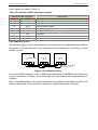
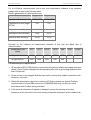
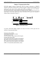
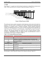
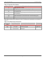
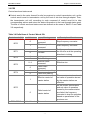
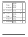
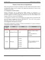
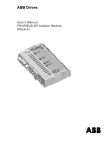
User Manual EPC-CM2 PROFIBUS-DP Industrial Site Bus Adapter EPC-CM2 Instruction Manual Preface Thanks for you to use EPC-CM2 (Profibus-DP) industrial site bus adapter manufactured by Jiangsu GTAKE Electric Co., Ltd. The User Manual introduces the contents in installation of wiring, precautions and applications etc. of EPC-CM2 adapter in details. Before its use, make sure to read the safety precautions of the manual carefully to ensure the safety of people and equipment in using the product. Readers Readers of the manual are the personnel in charge of debugging and the users of EPC-CM2 adapter module. The readers need to be qualified with basic electric knowledge, electric wiring experience and knowledge on operation of transmission unit. Preparations Before starting the installation of EPC-CM2 adapter, the transmission unit shall be installed and put into use. In addition to preparation of routine installation tools, the manual of transmission unit shall be prepared as well, for the manual includes a lot of important information without being contained in the user manual. So, it is necessary to read it in the installation process. Safety instructions Electric installation and maintenance of all transmission units shall be finished by qualified electric engineer. Transmission unit and its adjacent equipment must be connected to the ground correctly. Do not operate transmission device with power on. After cutting off the main power, wait for at least 5min and then operate frequency converter, motor or motor cable after the power of capacitance of the middle loop is discharged completely. In connecting the main power, the terminal of motor cable is at hazardous state no matter whether the motor is operated or not. Please do not touch it. Table of Contents Chapter 1 Overview ............................................................................................................................- 1 1.1 Profibus criteria ...........................................................................................................................- 1 1.2 Profibus-DP adapter ...................................................................................................................- 1 Chapter 2 Installation and Wiring .....................................................................................................- 2 2.1 Mechanical and electrical installation .........................................................................................- 2 2.2 DIP switch ...................................................................................................................................- 3 2.3 Bus interface ...............................................................................................................................- 3 2.4 Connection of bus .......................................................................................................................- 4 2.5 Instructions on applications ........................................................................................................- 5 Chapter 3 Communication Data........................................................................................................- 6 3.1 PKW ............................................................................................................................................- 7 3.2 PZD ...........................................................................................................................................- 11 Chapter 4 Instructions on Applications .........................................................................................- 15 4.1 Configuration of master station ................................................................................................- 15 4.2 Configuration of frequency converter .......................................................................................- 15 4.3 Transmission ratio ....................................................................................................................- 18 Appendix Status Indications ...........................................................................................................- 19 - EPC-CM2 User Manual Chapter 1 Overview Chapter 1 Overview 1.1 Profibus criteria Profibus is a kind of open serial communication standard, which can be adopted to realize mutual exchange of data among various types of automatic elements. Profibus is mainly divided into three types: Profibus-FMS (Fieldbus Message Specification), Profibus-DP (Decentralized Periphery) and Profibus-PA (Process Automation). The physical transmission media of bus is twisted-pair cable (conform to RS-485 standard). The max length of bus cable is controlled within the range of 100-1200m with its specific length determined by the selected rate of transmission. 31 nodes at most can be connected to the same Profibus network segment without the use of repeater. If the repeater is used, the number of nodes (including repeater and main station) connected to network can be increased to 127. In Profibus communication, it is the main station that selects the nodes to respond to command of the host, which can issue commands to numerous nodes in the form of broadcast; under such circumstance, it is not necessary for the nodes to send feedback signal to the host. 1.2 Profibus-DP adapter EPC-CM2 adapter module is an optional equipment of Jiangsu GTAKE Electric Co., Ltd. and it can be used to connect transmission unit with a Profibus network. On Profibus network, the transmission unit is considered as passive equipment. EPC-CM2 adapter can be used to: Send control command (such as operating, stop and inching control etc.) to transmission unit Send signal with given frequency to transmission unit Send process data to transmission unit Read status signal and actual value from transmission unit Change the parameter value of transmission unit Reset faults of transmission unit -1- Chapter 2 Installation and Wiring EPC-CM2 User Manual Chapter 2 Installation and Wiring 2.1 Mechanical and electrical installation Plug three nylon columns into corresponding holes of control panel (it is ok to select any of the two groups on the left or right of GK800) Cover insulated spacer to nylon column flatwise Plug EPC-CM2 card into corresponding slot (it is ok to select any of the two groups on the left or right of GK800), ensure the aligning of three installation holes at nylon columns and fix them with three self-tapping screws Plug bus connector of SIEMENS standard into CN1 of DB9 socket of EPC-CM2 and fix its tail screw Connect grounding terminal J1 of EPC-CM2 card with the shell of frequency converter. Figure 2.1 EPC-CM2 adapter -2- EPC-CM2 User Manual Chapter 2 Installation and Wiring 2.2 DIP switch The one indicated in Figure 2.2 is the DIP switch. DIP 1 and DIP 2 bits are correspondent with the terminal resistance of Profibus bus. When it is dialed to “ON”, the terminal resistance will be effective. The ones from DIP 3 to DIP 6 bits are correspondent with the options of MODBUS communication Baud rate, or 9600bps, 19200bps, 38400bps and 57600bps respectively. If the DIP switch of certain Baud rate is at “ON” state and the other three DIP are of “OFF” state, it means the selection of the Baud rate. If the ones from 3 to 6 cannot meet the requirement of above combination, the Baud rate of communication is defaulted to be 19200bps. Terminal resistance 终端电阻 9600bps 19200bps 38400bps 57600bps Figure 2.2 DIP switch 2.3 Bus interface EPC-CM2 adapter is qualified with two Profibus DP interfaces: “terminal” or “standard DB9 connector”; and users may select wiring method according to actual situations. Terminal is a 4-Pin socket and its pin signals’ correspondence relations are indicated in Table 2.1. Table 2.1 Terminal signals 4-Pin terminal Instructions 1 A Cathode of data line 2 B Anode of data line 3 GND 4 PE Communication data ground Protection ground The configuration of signals with standard DB9 connector shall meet Profibus standard as indicated in Figure 2.3. Figure 2.3 DB9 connector -3- Chapter 2 Installation and Wiring EPC-CM2 User Manual Its pin signals are listed in Table 3.2 Table 3.2 Contrast of DB9 connector’s signals Standard DB9 connector 1 NC 2 NC 3 B 4 RTS 5 GND 6 +5V 7 NC 8 A 9 NC Instructions Unused Unused Anode of data line Send request signal Isolator Isolated 5V DC voltage power supply Unused Cathode of data line Unused 2.4 Connection of bus The following figure is about the connection of terminal and the cable shield layer shall be connected to the ground; users may select the best grounding way according to actual situation on site. Master station Figure 2.4 Connection of bus For wiring of DB9 connector, refer to DB9 wiring instructions of SIEMENS. If the Baud rate of bus is more than 187.5kbps, carry out wiring in strict accordance with wiring standards of Profibus. Note: in Profibus network, the terminal resistance of the stations at the head and end of bus needs to be started, but the terminal resistance of middle station shall be closed. -4- EPC-CM2 User Manual Chapter 2 Installation and Wiring For the Profibus communication wire’s type and transmission distance to be adopted, please refer to data in the following table. Electric parameters of transmission wires Parameters A type wire B type wire Impedance/Ω 135~165 100~130 Capacitance of unit length /(PF/M) <30 <60 Loop resistance/(Ω/km) 110 - Diameter of wire core/mm 0.64 >0.53 Section of wire core/mm2 >0.34 >0.22 Contrast on the relations of transmission distance of bus with the Baud rate of communication. 9.6 19.2 93.75 187.5 500 1500 12000 Transmission rate (kbps) A type wire (m) 1200 1200 1200 1000 400 200 100 B type wire(m) 1200 1200 1200 600 200 - - 2.5 Instructions on applications 1. PE terminal of EPC-CM2 shall be connected to the ground reliably and copper core wire above 3.5mm2 shall be adopted as the grounding wire with its grounding resistance less than 10Ω as well; 2. Three screws on the adapter shall be fixed well to ensure their reliable connection with frequency converter; 3. When the transmission rate of bus reaches 187.5kbps, please use special Profibus communication line and DB9 connector of SIEMENS and carry out wiring in strict accordance with Profibus wiring standard; 4. If the terminal resistance of adapter is adopted, ensure the opening of terminal resistance at the two ends of bus and closing of terminal resistance at the middle node. -5- Chapter 3 Communication Data EPC-CM2 User Manual Chapter 3 Communication Data EPC-CM2 adapter supports Profibus-DP (DP-V0) protocol conforming to EN50170 standard. Profibus-DP communication visits the services of data link layer through service access point and each service access point (SAP) in Profibus has clear definition. Specifically, please refer to user manual of main site of related Profibus. In cyclic communication, Profibus-DP Protocol adopts the type of PPO (Parameter/Process Data Object) as the data transmission format and different PPO types are composed of different data as indicated in Figure 3.1. PKW PZD Figure 3.1 PPO Data Format At present, EPC-CM2 adapter supports the above five kinds of PPO types with the definition of data described below: Parameter district (PKW): ID- parameter identification number IND- parameters’ index VALUE- parameter value (4 bytes as the longest) Process data district (PZD): CW- Control word (from the master to the passive) SW- Status word (from the passive to the master) REF- Given value (from the master to the passive) ACT- Actual value (from the passive to the master) PZD3~10- Process data (determined by users) -6- EPC-CM2 User Manual Chapter 3 Communication Data 3.1 PKW From Figure 3.1, it can be seen that the data of parameters is transmitted in message types PPO1, PPO2 and PPO5 and it consists of 8 bytes as indicated in Figure 3.2. ID 15 14 13 12 11 10 9 8 IND 7 6 5 4 3 2 1 0 8位 VALUE 8位 16位 16位 Command number/response 命令号/响应号 number 请求信号(保留) Request signal (retained) High word of Profibus protocol Profibus协议参数号高位 parameter number 功能码组号 Group number of functional code 功能码组内索引 Inter-group index of functional codes 保留 Retained 功能码参数高字 High word of functional code parameters 功能码参数低字 Low word of functional code parameters Figure 3.2 Data Format of PKW ID includes two bytes, of which command number/response number ranks at the high four positions. The visit of PKW is divided into two types: Profibus protocol parameters and parameters of functional code of frequency converter. Profibus protocol’s parameter number is correspondent with the low 11 bits of ID and ID low bytes and IND high bytes are combined for visit to parameters of functional code. If the parameters of functional code are visited, the high bit of Profibus protocol parameter number (bits from ID8-10) must be 0; otherwise, the response package will report the error of illegal parameter number. According to PROFIDRIVE routine, the adapter selects command/response number to meet specific requirements as indicated in Table 3.1. Table 3.1 ID Command/Response Number Command number 0 1 2 Description of functions No task Request for reading the parameter data of functional code Request for changing the parameter data of functional code Request for modifying the parameter data of functional code and 14 store it to EEPROM Other Retained Response number Description of contents 0 No response Correct operation to parameters of functional code (reading or 1 modification) Impossible execution with wrong information returned at the middle 7 and low bytes in VALUE Other Retained In case of error occurring to operation of parameters, the code of error will be returned in the low bytes of VALUE and the contents of error code are defined in Table 3.2. -7- Chapter 3 Communication Data EPC-CM2 User Manual Table 3.2 Operation Error Number Error number 0 1 2 12 101 Description of contents Illegal parameter number Setting of parameters is not allowed (read only) The value of parameter exceeds the limit Wrong password Impossible modification to parameter data (impossible modification in its operation) 102 Communication fault 104 Failed modification to functional code or data exceeding limit 105 Illegal command number Other Reserved EPC-CM2 provides partial reading and visits of Profibus protocol parameters as indicated in Table 3.3. Table 3.3 Profibus Protocol Parameters Parameter number 918 929 963 Name of parameter Address of site PPO type Baud rate of communication Instructions Address of passive station Current PPO type Current Profibus communication Baud rate -8- Property Read only Read only Read only EPC-CM2 User Manual Chapter 3 Communication Data In visiting the functional code of frequency converter, the group number of corresponding functional code for low byte of ID and the relations between them are indicated in Table 3.4, and the high byte of IND is correspondent with the inter-group index one-to-one and low byte of IND is retained to be 0 all the time. Table 3.4 Correspondence relations of ID low byte with group number of functional code Low 8 bits of ID Group number of Low 8 bits of ID Group number of functional code functional code 0x00 A0 0x11 E0 0x01 A1 0x12 E1 0x02 b0 0x13 F0 0x03 b1 0x14 F1 0x04 b2 0x15 F2 0x05 C0 0x16 F3 0x06 C1 0x17 F4 0x07 C2 0x18 F5 0x08 C3 0x19 F6 0x09 C4 0x1A H0 0x0A d0 0x1B H1 0x0B d1 0x1C H2 0x0C d2 0x1D L0 0x0D d3 0x1E L1 0x0E d4 0x1F U0 0x0F d5 0x20 U1 0x10 d6 0x21 U2 Parameter value of functional code of frequency converter only occupies two bytes. So, the high bit in VALUE is retained and the parameter value is returned in low bytes. Examples of parameters’ data transmission Example 1: read the parameters of Profibus protocol In order to run the parameters of Profibus protocol, low 11 bits of ID are adopted for identification of parameter number. As the adapter only provides the reading operation for the ones with parameter number to be 918, 929 and 963 at present, the index value IND is 0 all the time. For example, for reading parameter 918, switch the parameter number into 396H in hexadecimal system with the returned parameter value to be 4, or the address of the station. The specific transmission of data is indicated as follows: -9- Chapter 3 Communication Data EPC-CM2 User Manual Command (read parameters) Parameter number(396H) Sub-index Command Response Parameter value Sub-index Parameter number Response (correct Example 2: rewrite the parameters of functional code The parameter of functional code will perform addressing in combining low byte of ID with high byte of IND; at this moment, the ones from ID8 to ID10 must be 0. For example, modify the upper frequency b0-09 of the system into 100.00HZ with corresponding parameter number to be 0209H and parameter value to be 2710H (10000) as well as command and response format indicated as follows: Command (rewrite parameters) Parameter number Sub-index Parameter value Command Response Parameter value Sub-index Parameter number Response (correct operation) If the parameter is set to exceed the limit, the following format will be returned. Sub-index Parameter value Response (correct operation) Response Error number - 10 - EPC-CM2 User Manual Chapter 3 Communication Data 3.2 PZD Control word and status word Control word is the main channel for site bus system to control transmission unit; as the control word is sent to transmission unit by the host of site bus through adapter. Then, the transmission unit will, according to code command of control word bit to take corresponding actions and return the status information to the host through status word. The bits of control word and status word are defined as the ones in Table 3.5 and Table 3.6 respectively. Table 3.6 Definitions of Control Words’ Bit Control word (bit) Value 1 Meaning Failed operation command Effective operation command Inversion 0 Forward 1 0 Inching Failed inching Effective reset command Failed reset command Effective free parking Failed free parking 0 BIT0 1 BIT1 BIT2 0→1 BIT3 0 BIT4 1 0 1 Effective control of master station 0 Failed control of master station BIT5 BIT6~BIT15 Undefined Reserved - 11 - Description of functions Stop frequency converter Start frequency converter Set the operation command to be effective and the operating direction in inching Effective rise The current control word and set value of operation issued by the master station are effective As the current control word and set value of operation issued by the master station are failed, the frequency converter is kept for operation based on parameters of the previous one. Chapter 3 Communication Data EPC-CM2 User Manual Table 3.6 Definition of Status Word Bits Status word (bit) Value 1 BIT0 0 1 0 Failed free parking 1 0 Inching operation Non-inching operation Faults of frequency converter No fault of frequency converter Faults of adapter Normal adapter Effective selection of communication with command source Failed selection of communication with command source Reserved BIT1 0 1 BIT3 BIT4 0 1 BIT5 0 BIT6 1 0 1 BIT7 0 BIT8~BIT15 Stopping of frequency converter Inversion of frequency converter Forward of frequency converter Reach the master setting Without reaching master setting Effective free parking 1 BIT2 Meaning Operation of frequency converter Undefined Description of functions Whether the frequency converter is at operating status; in inching, the bit is set as well. Status bit of operating direction Whether the command of free parking is effective. If it is effective, prohibit its operation Status bit of faults to frequency converter REF/ACT/PZDx In PPO1 and PPO3, PZD2 is defaulted to be given main frequency and feedback of operating frequency in the speed control model. In other PPO, PZD2-10 can be set to be specific functional code’ parameter, control parameter and status parameter according to the needs of users; and their correspondence relations can be set in functional codes of group H1 as indicated in Table 3.7. - 12 - EPC-CM2 User Manual Chapter 3 Communication Data Table 3.7 Selection of functional code for data transmission of PZD Functional code Name H1-02 PZD2_OUT(the master →the passive) H1-03 PZD3_OUT(the master →the passive) H1-04 PZD4_OUT(the master →the passive) H1-05 PZD5_OUT(the master →the passive) H1-06 PZD6_OUT(the master →the passive) H1-07 PZD7_OUT(the master →the passive) H1-08 PZD8_OUT(the master →the passive) H1-09 PZD9_OUT(the master →the passive) H1-10 PZD10_OUT(the master →the passive) H1-11 PZD2_IN(the passive →the master) H1-12 PZD3_IN(the passive →the master) Scope 0: none Its property as writable functional code 0x6200~0x6214 0: none Its property as writable functional code 0x6200~0x6214 0: none Its property as writable functional code 0x6200~0x6214 0: none Its property as writable functional code 0x6200~0x6214 0: none Its property as writable functional code 0x6200~0x6214 0: none Its property as writable functional code 0x6200~0x6214 0: none Its property as writable functional code 0x6200~0x6214 0: none Its property as writable functional code 0x6200~0x6214 0: none Its property as writable functional code 0x6200~0x6214 0: none A0-00~U2-xx 0x6200~0x6214 0x6300~0x6323 0: none A0-00~U2-xx - 13 - Ex-factory value Property 0 △ 0 △ 0 △ 0 △ 0 △ 0 △ 0 △ 0 △ 0 △ 0 △ 0 △ Chapter 3 Communication Data H1-13 PZD4_IN(the passive →the master) H1-14 PZD5_IN(the passive →the master) H1-15 PZD6_IN(the passive →the master) H1-16 PZD7_IN(the passive →the master) H1-17 PZD8_IN(the passive →the master) H1-18 PZD9_IN(the passive →the master) H1-19 PZD10_IN(the passive →the master) EPC-CM2 User Manual 0x6200~0x6214 0x6300~0x6323 0: none A0-00~U2-xx 0x6200~0x6214 0x6300~0x6323 0: none A0-00~U2-xx 0x6200~0x6214 0x6300~0x6323 0: none A0-00~U2-xx 0x6200~0x6214 0x6300~0x6323 0: none A0-00~U2-xx 0x6200~0x6214 0x6300~0x6323 0: none A0-00~U2-xx 0x6200~0x6214 0x6300~0x6323 0: none A0-00~U2-xx 0x6200~0x6214 0x6300~0x6323 0: none A0-00~U2-xx 0x6200~0x6214 0x6300~0x6323 - 14 - 0 △ 0 △ 0 △ 0 △ 0 △ 0 △ 0 △ EPC-CM2 User Manual Chapter4 Instructions on Applications Chapter 4 Instructions on Applications After correct wiring and connection of hardware, the master station and the passive station in Profibus-DP network must be configured with appropriate parameters to ensure normal operation of the system. 4.1 Configuration of master station Network configuration can be realized with STEP7 software. In configuration, it is necessary to provide corresponding GSD file. GSD file of EPC-CM2 adapter will be provided in delivery of product or users may download it from the official website of our company. GSD file is named as EPC0689.gsd. In configuration of hardware, firstly install GSD file and update directory so that EPC-CM2 device will appear in equipment directory “PROFIBUS DP”. Then, add it to the network. Specifically, refer to STEP7’s Use Instructions. 4.2 Configuration of frequency converter After finishing configuration of network, correctly set parameters of H1 group according to configuration situation of master station. Functional code H1-00 Name Address of the site Scope Instructions 0 is usually used as the address of class 2 master station 1~127 127 as the address of broadcast 0: Profibus failed 1: PPO1 2: PPO2 H1-01 PPO type 3: PPO3 PPO type shall be set to be one type of PPO1-5. 4: PPO4 5: PPO5 Note: H1-00 and H1-01 do not support online modification; after modification, it will be put into effect only with re-powering on. - 15 - Chapter 4 Instructions on Applications EPC-CM2 User Manual For realizing the communication control of master station, the following functional codes shall be set: Functional code b1-00 Name Value Instructions Given method of 2 Communication control operating command H0-00 Selection of 485 1 Make expansion card input port’s terminal resistance H0-02 Address of 485 port’s 5 The address of the computer is fixed to communication be 5. computer According to DIP switch of EPC-CM2, select appropriate Baud rate of local communication Functional code Name Scope Instructions The unit: the selection of Baud rate 1: 9600bps 2: 19200bps 3: 38400bps Communication 4: 57600bps Data format: 1-8-2-N, RTU; H0-01 configuration of The tens: format of Direct cable connection; Baud 485 port data rate: 9600~57600bps optional 0: 1-8-2-N format, RTU Hundreds: wiring method 0: direct cable connection If PPO1 or 3 is adopted as the transmission type, PZD2 is fixed with given main frequency so that it is applicable to speed control model. At this moment, set corresponding functional code as follows: Functional Name Value Instructions code b0-01 Main given 9 Communication input method of frequency In other PPO types, the correspondence relation of PDZ2-10 with the functional code, control parameter and status parameters can be set in H1-02~ H1-19; and it can be changed online. Please set it correctly. EPC-CM2 supports the test of bus faults, users may set the process mode of faulted frequency converter through H1-20 functional codes and corresponding fault or warning code (PFS) will be presented on the operating panel. - 16 - EPC-CM2 User Manual Functional code H1-20 Chapter4 Instructions on Applications Name Process mode to faults of bus Scope 0: fault with free parking 1: warning with continuous operation - 17 - Instructions The process mode to faults of bus is adopted to set the process mode of frequency converter in case of faults occurring to bus. Chapter 4 Instructions on Applications EPC-CM2 User Manual 4.3 Transmission ratio The value of functional code of frequency converter is equipped with five types of precision: 1, 0.1, 0.01, 0.001 and 0.0001; and the transmission ratio is the reciprocal of corresponding precision. For example, the main given number of frequency sets the precision of b0-02 to be 001; then, the transmission ratio will be 100; if it is set to be 50.00HZ, the transmission value of bus will be 5000 (1388H) If the precision of Ti1 d2-02 of ASR high-speed integral time; then, transmission ratio will be 1000; if it is set to be 0.500, the transmission value of bus will be 500 (1F4H). - 18 - Appendix Status Indications EPC-CM2 User Manual Appendix Status Indications EPC-CM2 adapter is set with three signal lamps: Run, Local and Network, whose status will indicate the current working situation of adapter with the specific ones indicated in Table 4.1. Table 4.1 Status Indications Status LED1 green (Run) LED2 green (Local) LED3 green (Network) Off Off Off On Twinkle Twinkle On Off On On On Twinkle On On Off Faults of bus On On On Normal - 19 - No power for Profibus card Abnormal test of RAM Local faults In establishing communication - 20 - JIANGSU GTAKE ELECTRIC CO., LTD. No.3058, Jintong Road, Nantong City, Jiangsu Province Tel: 86-0513-86392601 Fax: 86-0513-86221809 JIANGSU GTAKE ELECTRIC CO., LTD. SHENZHEN BRANCH Building 10, Zhong-yun-tai Industrial Park, Tangtou Road NO.1, Bao'an District, Shenzhen, Guangdong Province, China Tel: 86-0755-86392609 Fax: 86-0755-86392603 Http://www.gtake.com.cn Copyright ©2011 JIANGSU GTAKE ELECTRIC CO., LTD. All Rights Reserved Code: 34.01.0025 We reserve the right to change the information in this manual without prior notice. Version: A00