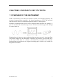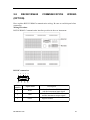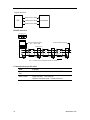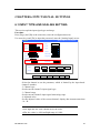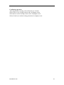
1
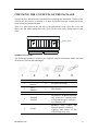
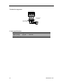
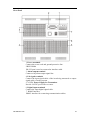
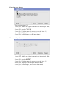
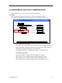
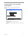
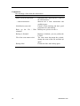
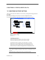
2.3 INPUT AND OUTPUT SIGNAL WIRING
Here will explain the measurement of input / output signal lines. Be sure to read this
section before connecting the input and output signal wiring.
Caution
If a strong tension is applied to the cable wired to the instrument, the
terminals of the instrument and the cable can be damaged. In order to
prevent tension from being applied directly on the terminals, fasten all
wiring cables to the rear of the mounting panel.
Precautions to be taken while wiring
Take the following precautions when wring the input signal cables.
It is recommended that crimp-on lugs (designed for 4 mm screws) with insulation
sleeves be used on the lead wire ends.
Take measures to prevent noise from entering the measure ment circuit.
●Move the measurement circuit away from the power cable (power circuit) and
ground cable.
●It is desirable that the item being measured does not generate noise. However, if this
is unavoidable, isolate the measurement circuit from the item. Also, ground the item
being measured.
●Shielded wires should be used to minimize noise caused by electrostatic induct ion.
Connect the shield to the ground terminal of the instrument as necessary (make sure
you are not grounding at two points).
●For the interference generated by electromagnetic induction, if splicing the
equidistant dense circuit wiring, it will be more effective.
●The resistance of ground terminal is lower.
When using the the rmocouple input, take measures to stabilize the temperature
at the input te rminal.
●Always use the input terminal cover.
●Do not use thick wires which may cause large heat dissipa tion (cross sectional area
0.5mm2 or less recommended).
●Make sure that the ambient temperature remains reasonably stable. Large
temperature fluctuations can occur if a nearby fan turns ON or OFF.
Connecting the input wires in parallel with other devices can affect measured value.
If you need to make a parallel connection, then
● Ground the instruments to the same point.
●Do not turn ON or OFF another instrument during operation. This can have adverse
effects on the other instruments.
●RTD cannot be wired in parallel.
●Current signal cannot be wired in parallel.
IM01B82R01-01E
17