1
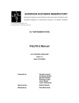
B. F. D.
RUN
STOP
O
N
P
O
W
E
R
FWD
MOM
REV
CON
OFF
BARTECH
F OCUS
DEVICE
POWER
IN
DATA
OUT
BarTech Focus Device
Owners Manual
Table of Contents
Introduction………..………………………………………………………………………………..2
Transmitter…………………………………………………………….…………………………..2
Transmitter Controls…..……………………………………………….…………………….…..3
Transmitter Indicators….………………………………….……………………………………...4
Transmitter Connectors………………….……………………………………………...………..4
Transmitter Battery……………………………………..………….....…………………………..4
Receiver/Amplifier…………………………………….………………..…………………………..4
Receiver/Amplifier Controls…..…………………………….………………………..…………..5
Calibration Procedure…..……………………………………..……….…………………………6
Receiver/Amplifier LED…… ……………………………………………….…………………….7
Receiver/Amplifier Connectors…..………………………………...…………………….……..7
Other Things to Know…………..…………………………………………………………………..8
Warranty………………………………..…………………………………………………………….8
Troubleshooting…..………………………….……………………………………………………9
Connector Pinout…..……………………………………………………………………………10
Specification…..……………………………………………………………………………...….11
Technical Support…….……………………………………..………………………………….11
Page 1
Introduction
Congratulations! You are now in possession of one of the most popular wireless follow
focus systems in the world. Since its introduction in 1999 the BarTech Focus Device, or
BFD , has been sold by the hundreds all over the world. We hope you will enjoy using it
as much as we enjoyed developing it. Please feel free to contact us if you have any
questions or comments.
The BFD Unit
A BFD unit consists of a hand-held Transmitter control, a Receiver/Amplifier motor
driver unit, and a power cable. To control a lens, a lens drive motor and motor cable
are required. To start and stop a camera a remote control, or “run/stop” cable is
required.
The Transmitter
The transmitter control unit, called just the ”Transmitter”, is a small, lightweight, handheld unit that enables the operator to remotely control one lens function, such as focus
or iris, and start or stop the camera. The Transmitter has one main lens control knob
(either a rotary knob or a slider) three toggle switches for power and setup, one rocker
switch for camera on/off, one rotary selector switch for channel selection, two LED’s,
two connectors and one 9V battery.
Page 2
Transmitter Controls
Control Knob: Each Transmitter has one main control knob, either a rotary knob or a
linear slider. Once the lens drive motor has been calibrated to the lens at
the Receiver/Amplifier, end-to-end travel of the knob moves the lens
through the range set during calibration. The travel can be set to be the
entire range of lens movement or between two intermediate points, as
desired by the operator. An important point to note is that the smaller the
range of travel of the motor, the more accurate the system becomes.
(This is the opposite of all other systems currently in use, which have
either a fixed accuracy or get less accurate as the range is reduced)
POWER Switch: The power switch turns power on and off to the Transmitter.
FWD/REV Switch: This switch reverses the direction of travel of the lens drive motor in
response to a movement of the control knob. The forward/reverse
designations are completely arbitrary, so simply choose whichever
matches the operator’s needs. The motor calibration does not need to
be redone when the direction is changed.
MOM/CONT Switch: This switch is used to select the desired operation of the camera
run/stop relay in the Receiver/Amplifier. Some cameras, such as an ARRI
16SR or 35-III require the external contact closure to be maintained
continuously for as long as the camera is running. Other cameras, such
as the Moviecam Compact, require a momentary contact closure to start
the camera and another momentary closure to stop the camera. This
switch is set to CONT for continuous operation cameras and MOM for
momentary operation cameras.
RUN/STOP Switch: This switch is used to activate the relay in the Receiver/Amplifier
that is used to put a film or video camera in the run or stop mode.
CHANNEL Select Switch: This switch is used to select one of the eight frequencies in
the 900 MHZ range for operation. The selector switch must be set to the
same channel on both the Transmitter and Receiver/Amplifier. As a
general rule, use the highest number that works in order to minimize
interference from video transmitters. If two BFD units are being used at
once, leave at least one unused channel between the two channels
being used, i.e. do not set the units on adjacent channels, such as 5
& 6! Also, do not use channels 3 & 7 simultaneously, as you may get
interference.
Page 3
Transmitter Indicators
POWER LED: The red/green power LED has four modes of operation:
Green: Unit on and transmitting, battery voltage OK.
Flashing Green: The unit has not been used for more than 15 minutes, so
the RF transmitter has been turned off to save power. Changing any
control or moving the knob turns the transmitter back on within 15 /1000 of
a second.
Red: The LED will turn red approximately 1 hour before the 9V battery
needs replacement.
Flashing Red: The LED will begin flashing red when the battery voltage
has gotten so low the transmitter can no longer function accurately. The
RF transmitter will be shutdown to prevent inaccurate operation.
RUN/STOP LED: The blue run/stop LED flashes when the camera run/stop switch is in
the run position.
Transmitter Connectors
POWER IN Connector: This 2-pin connector is provided to allow the BFD Transmitter
to be powered by an external battery. The Transmitter will operate on any
voltage from 7 to 15 VDC. It draws 30 milliamps of current. Pin 1 is
positive, pin 2 is negative.
DATA OUT Connector: This 3-pin connector is provided to allow direct connection of
the Transmitter and the Receiver/Amplifier unit. When connected, the RF
sections in both the transmitter and receiver are switched off and the serial
data is sent via a cable. Pin 1 is ground, pin 2 is the RF shutdown line
that must be connected to pin 1 in the cable, and pin 3 is the serial data
output line.
Transmitter Battery
The Transmitter is powered by a standard 9V battery that is inserted through the bottom
plate. An alkaline 9V battery will provide 18 hours of operation. The battery is inserted
with the negative contact near the power connector. Inserting the battery backwards
will have no effect, the unit simply will not operate.
The Receiver/Amplifier
The Receiver/Amplifier unit is a small, lightweight unit that is placed near the lens being
controlled. It receives the signal from the Transmitter and drives the lens drive motor
proportionally to the movement of the Control Knob. It also has a relay that can be used
to control the run/stop function of film & video cameras. The unit has a toggle switch for
power, a rotary switch for channel selection, a 3-position toggle switch and two barrelshaped thumb wheels for calibrating the lens drive motor’s range of travel to the desired
range of lens travel, one LED and six connectors.
Page 4
Receiver/Amplifier Controls
ON/OFF Switch: This switch controls power to the Receiver/Amplifier
CHANNEL Select Switch: This switch is used to select one of the eight frequencies in
the 900 MHZ range for operation. The selector switch must be set to the
same channel on both the Transmitter and Receiver/Amplifier. As a
general rule, use the highest number that works in order to minimize
interference from video transmitters. If two BFD units are being used at
once, leave at least one unused channel between the two channels
being used, i.e. do not set the units on adjacent channels, such as 5
& 6! Also, do not use channels 3 & 7 simultaneously, as you may get
interference.
Calibration Switch and Thumbwheels: These controls, located on the side or the
Receiver/Amplifier, are used to set the end points of travel of the lens
drive motor that correspond to the range of travel of the Control Knob on
the Transmitter. See following page for the calibration procedure.
Page 5
Page 6
Receiver/Amplifier LED
STATUS LED: This red/green has three modes of operation:
Red: The unit is on but not receiving a signal from the Transmitter
Green: The unit is on and receiving a signal from the Transmitter
Flashing Red/Green: In calibration mode (the toggle switch is not in the
center “operate” position).
Note: When the signal is being interfered with and reception is intermittent,
the LED may appear a yellow-orange color as it switches back and forth
rapidly between red and green.
Receiver/Amplifier Connectors
PWR Connectors: There is a 2-pin power input/output connector at each end of
the Receiver/Amplifier unit. Either one may be used for connection to an
external 11 to 17VDC power source. If two BFD’s are being used and
only one power source exists, plug the second Receiver/Amplifier’s cable
into the unused power connector on the first one. Pin 1 is positive, pin 2 is
negative.
DATA IN Connector: This 3-pin connector is provided to allow direct connection of the
Transmitter and the Receiver/Amplifier unit. When connected, the RF
sections in both the transmitter and receiver are switched off and the serial
data is sent via a cable. Pin 1 is ground, pin 2 is the RF shutdown line
that must be connected to pin 1 in the cable, and pin 3 is the serial data
input line.
MTR Connector: The 5-pin motor connector is used to connect the Receiver/Amplifier to
a lens drive motor. The pin assignments are 1-for-1 compatible with Seitz
and WRC-4 systems and Heden and Cinema Products motors.
POT Connector: This 4-pin connector is provided to allow direct connection of a 10K
control potentiometer to be used instead of the transmitter. This way, a
very small control knob may be placed anywhere convenient for the
operator. When used this way, the Receiver/Amplifier becomes a direct
analog servo control system (like a Preston “Micro Force”). The
calibration knobs still set the ends of lens travel, but the calibration is
slightly different. The calibration toggle switch has no effect and should be
set in the middle position. Simply move the remote pot control all the way
to one end of its travel. At this point, one of the calibration wheels will
have a large effect on its operation, and one will have little effect. Use the
one which has a large effect to set the end of motor travel point. Move the
remote pot to the other end of its travel and repeat with the other wheel.
Pins 2 & 4 are connected to the pot’s end points, and pin 3 to the pot
wiper.
Page 7
CAM Connector: This 4-pin camera run/stop connector is used to put film or video
cameras in the “run” mode and stop them. Special cables are required for
each camera. This connector is compatible with the Seitz system. Pin 2
is the normally open relay contact and pins 3 & 4 are the relay common.
Note: As a special order, this connector can be replaced by a 2-pin
connector for compatibility with WRC-4 and modified Seitz units. If the 2pin connector is used, Pin 1 is the normally open relay contact and pin 2 is
the relay common.
Other Things to Know
Interference from Video Transmitters: UHF video transmitters, such as the Modulus
2000 or 3000, tend to broadcast on other frequencies than the intended frequency. This
can block the signal from reaching the Receiver/Amplifier. There are several things you
can do to prevent this from being a problem:
1. Never use any channel above 50 UHF for transmission. The lower the channel
the lesser the chance of interference. Channels below 40 generally do not
interfere at all unless the video transmitter is inches away from the antenna on
Receiver/Amplifier.
2. Use the highest channel on the BFD that is interference free.
3. Keep as much metal (such as the camera body) between the Video transmitter
and the BFD Receiver/Amplifier.
4. Keep the video transmitter antenna and cables as far away from the BFD
antenna and cables as possible.
Motor Driver Shutdown: In order to save power, reduce heat generation and prevent
motor “jumping” due to stray RF interference, the Receiver/Amplifier turns off the motor
driver circuitry 1.5 seconds after the motor reaches its desired position. After 7 seconds
of trying unsuccessfully to reach the desired position, the motor will be turned off to
prevent damage to the motor or BFD unit. Changing the position of the control knob on
the transmitter reactivates the motor driver circuitry and resets the timer.
Battery Saver: When the Transmitter has not been used for more than 15 minutes the
RF transmitter is turned off to save power and the power LED blinks green. Changing
any control or moving the knob turns the transmitter back on within 15 /1000 of a
second. When in the lower power mode, a fully charged 9V battery will last over 60
hours.
Warranty
BarTech Engineering warranties the BFD for manufacturing defects or component
failure under normal operation for 1 year from the date of purchase. BarTech
Engineering will pay shipping UPS ground within the United States to return the unit
after repairs.
Page 8
Troubleshooting
I cannot get the receiver/amplifier to receive the signal from the transmitter
(receiver/amp LED stays red or flickers between red and green).
There are several possible causes for this:
• The calibration switch on the receiver is not in the operate (center) position. The
LED blinks red/green to indicate you are in calibration mode.
• Check that the transmitter and receiver/amplifier are set to the same channel.
• If you are using a video transmitter, turn it off and see if you get a good signal. If
so, try using a different channel on the video transmitter. If it is a Modulus, be
sure to set the lowest channel you can use.
• Check around for other sources of RF interference. Cell phones in use in the
immediate vicinity can also be a problem.
When I switch the calibrate switch towards one of the knobs or when I try to make
a fast move the motor moves in short jerks until it reaches position.
This is due to insufficient power being supplied to the BFD. When the BFD tries to
move the motor to position at full speed it can draw up to 3 amps of current. 12V
accessory outputs from cameras, such as an ARRI 435, are limited to less current.
When the BFD tries to move the motor the power shuts down to prevent burnout, which
causes the BFD to shut down. This in turn causes the power draw to drop off, which
allows the accessory power to rise back up and the cycle repeats itself.
When I switch the transmitter on the light on the receiver turns green but moving
the knob on the transmitter doesn’t make the motor move.
The most likely cause of this is that both calibration knobs are in the start position (rolled
all the way towards each other). This makes the range of motor travel nothing. Follow
the calibration procedure on page 6 first try moving the knob on the transmitter.
When I switch the camera to “RUN”, it moves a little and stops.
Set the “CON/MOM” switch to “CON”. See page 3 for a description of this switch’s
operation.
When I switch the camera to “RUN” it stops, and when I set it to “STOP” it runs.
This can occur when using a camera that has one pushbutton for both starting and
stopping the camera. When the switch on the BFD is set to “RUN” it momentarily
closes a relay to simulate the camera buttom being pushed. It does the same thing
when set back to “STOP”. If the camera was already running when the switch was set
to “RUN” it will cause the camera to stop and vice-versa. To get the camera and BFD
back into synchronization start (or stop) the camera one time by using the pushbutton
on the camera instead of the BFD.
When the signal is just barely getting through (LED flickering between red and
green) the motors will occasionally twitch or jump.
This can be fixed by upgrading your software. Contact us for more details.
Page 9
Connector Pinout
TRANSMITTER BOTTOM
POWER IN (p. 4)
1: +7 TO 15 VDC
2: GROUND
DATA OUT (p. 4)
1:GROUND
2: RF SHUTDOWN (SHORT TO GROUND)
3: DATA OUT
RECEIVER FRONT
DATA IN (p. 7)
PWR (p. 7)
1: +11 TO 17 VDC 1:GROUND
2: GROUND
2: RF SHUTDOWN (SHORT TO GROUND)
3: DATA IN
RECEIVER BACK
CAM(p. 8) PWR(p. 7)
1: N/C
1: +11 TO 17 VDC
2: N.O.
2: GROUND
3: COM
4: COM
POT(p. 7)
1: N/C
2: POT CCW (-) END
3: POT WIPER
4: POT CW (+) END
Page 10
MTR(p. 7)
1: MOTOR –
2: POT CCW (-) END
3: POT WIPER
4: POT CW (+) END
5: MOTOR +
Transmitter Specifications
Dimensions/Weight: approx. 7" by 3½” by 3” / approx. 1½ lbs.
Power Consumption: 30 Milliamps @ 7 to 15 VDC (9 milliamps in low power mode)
RF Transmission: 902-928 MHZ Single frequency, part 15 FCC compliant:
Channel Freq.. (MHZ).
0
903.37
1
906.37
2
907.87
3
909.37
4
912.37
5
915.37
6
919.87
7
921.37
Resolution: 10-bits (1024 steps), all steps always used.
Data Update Rate: 300 transmissions/second
Transmission Delay: 2.7 milliseconds
Receiver/Amplifier Specifications
Dimensions/Weight: approx. 4½" by 3½” by 1½” / approx. 11 oz.
Power Consumption: 50 milliamps @ 11-17VDC (Motor off) up to 3 amps max when
driving a motor
Power Output to Motor: 2 amps maximum @ 18 VDC (36 watts)
Lemo Connector Part Numbers
Connector
Power (Trans. & Rcvr/Amp)
Data In/Out (Trans. & Rcvr/Amp)
Pot Input (Rcvr/Amp)
Motor Output (Rcvr/Amp)
Camera Run/Stop (Rcvr/Amp)
Receptacle
ECG.0B.302.CLL
ECG.0B.303.CLL
ECG.0B.304.CLL
ECG.1B.305.CLL
ERD.0S.304.CLL
Plug
FGG.0B.302.CLAD42
FGG.0B.303.CLAD42
FGG.0B.304.CLAD42
FGG.1B.305.CLAD62
FFA.0S.304.CLAC42
An excellent source for Lemo compatible connectors is Custom Interface Technology in
Los Angeles, CA. Call 323-222-6401.
Technical Support
Address any technical question to:
BarTech Engineering
5285 East Appian Way
Long Beach, CA 90803
Tel: (562) 987-9159 (M-F 9:00 am/ 5:00 pm)
Fax: (815) 364-5240
e-mail: [email protected]
Page 11