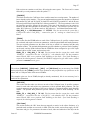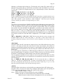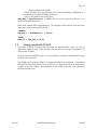
1
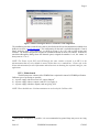
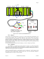
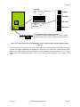
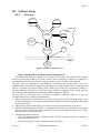
ELMB128 Documentation
"Everything you wanted to know about the ELMB128 but were afraid to ask"
J. R. Cook ([email protected]) & G. Thomas ([email protected])
February 2005
Page 1
CONTENTS
INDEX OF FIGURES .............................................................................................................................................2
INDEX OF TABLES ...............................................................................................................................................3
ORGANISATION OF THE MANUAL.................................................................................................................4
ORGANISATION OF THE MANUAL.................................................................................................................4
USEFUL LINKS ......................................................................................................................................................4
I.
INTRODUCTION AND QUICK START ....................................................................................................5
II.
HARDWARE SETUP ................................................................................................................................6
II.1.
OVERVIEW ................................................................................................................................................6
II.2.
HARDWARE INSTALLATION & CONFIGURATION ........................................................................................7
II.2.1.
National Instruments PCI-CAN-2 Interface ....................................................................................7
II.2.2.
Kvaser PCI CAN Card Interface .....................................................................................................7
II.2.3.
Motherboard....................................................................................................................................8
II.2.4.
Adapters...........................................................................................................................................9
II.2.5.
ELMB128.........................................................................................................................................9
III.
SOFTWARE SETUP................................................................................................................................11
III.1. OVERVIEW ..............................................................................................................................................11
III.1.1.
Introduction to CANBus and CANopen protocol...........................................................................11
III.2. SOFTWARE INSTALLATION & CONFIGURATION .......................................................................................12
III.2.1.
Files required. ...............................................................................................................................12
III.2.2.
CANopen OPC Server registration ...............................................................................................13
IV.
SETUP VERIFICATION ........................................................................................................................13
IV.1. DIAGNOSTIC TOOLS .................................................................................................................................18
IV.1.1.
NI Server Explorer.........................................................................................................................18
IV.1.2.
canhostplus ....................................................................................................................................18
IV.1.3.
CANalyser......................................................................................................................................25
V.
SOFTWARE APPLICATION DEVELOPMENT TOOLS & EXAMPLES...........................................26
V.1.
V.2.
CUSTOMIZING THE CANOPEN OPC SERVER ...........................................................................................26
GETTING STARTED WITH PVSS II ...........................................................................................................29
ANNEX A.
MOTHERBOARD SPECIFICATION ......................................................................................30
ANNEX B.
ELMB SPECIFICATION...........................................................................................................32
ANNEX C.
ADAPTERS SPECIFICATION .................................................................................................34
ANNEX D.
MOTHERBOARD CONNECTORS..........................................................................................37
REFERENCES: .....................................................................................................................................................41
Issue 4.3
ELMB128 Documentation
17/02/05
Page 2
Index of Figures
Figure 1: How to use this manual
5
Figure 2: Window showing the NI-CAN interface card configuration
7
Figure 3: Window showing the Kvaser CAN interface card configuration
8
Figure 4: Power connection of the ELMB Motherboard
9
Figure 5: Location and function of ELMB128 DIP-switches and the 10-pin Programmer/RS232 adapter
connector
10
Figure 6: Software Architecture View
11
Figure 7: Custom installation for installing the NICAN component
12
Figure 8: Address space of the OPC server using the NI Server Explorer
15
Figure 9: Example OPC configuration file as supplied with the CANopen OPC Server download
15
Figure 10: ELMB Node Guarding message using the CANalyzer
25
Figure 11: Nodes replying to a SYNC message with PDO-2 (ADC counts) in the CANalyzer
26
Figure 12: Back-side of the Motherboard showing the adapter connectors
30
Figure 13: Front-side of the Motherboard showing connectors
30
Figure 14: Implementation of the ELMB
33
Figure 15: Principle of the 3-wire resistance measurement
34
Figure 16: Plug-in adapter for 2 channels
34
Figure 17: Principle of the 2-wire measurements
35
Figure 18: Plug-in adapter for 4 channels
35
Figure 19: Principle of the differential attenuator
36
Figure 20: Plug-in adapter with differential attenuators
36
Figure 21: Plug-in adapter with resistor network
36
Issue 4.3
ELMB128 Documentation
17/02/05
Page 3
Index of tables
Table 1: Address space of OPC server when using the example OPC configuration file supplied in the
download, as shown in Figure 8
17
Table 2: ADC Input Connectors pin assignment
37
Table 3: PORT A pin assignment
37
Table 4: PORT C pin assignment
38
Table 5: PORT F pin assignment
38
Table 6: Microwire/SPI Interface pin assignment
39
Table 7: CANbus connector pin assignment
39
Table 8: Test Port pin assignment
40
Table 9: J29 pin assignment
40
Table 10: J30 pin assignment
40
Issue 4.3
ELMB128 Documentation
17/02/05
Page 4
Organisation of the Manual
Chapter I gives a brief overview of the equipment required for both software and hardware. A guide for
how to best use this manual is also given.
Chapter II supplies detailed information on how to set up the hardware for use with the ELMB128, its
powering and the associated interface cards.
Chapter III contains instructions for installing the required software and some background information
on the CANopen protocol and the CAN bus.
Chapter IV describes how to check that all required software and hardware has been installed correctly.
This does not test the application level of the installation, therefore allowing the same check to be
made, independent of the application software.
Chapter V explains how to customise the CANopen Server's configuration file for user defined
applications.
The Annexes contain detailed technical information for the motherboard, ELMB128 and adapters.
Useful Links
"CANopen High-level protocol for CANbus", H. Boterenbrood, April 1999,
http://www.nikhef.nl/pub/departments/ct/po/doc/CANopen20.pdf
Issue 4.3
ELMB128 Documentation
17/02/05
Page 5
I.
Introduction and quick start
Important Note for people who have been using older versions of the ELMB:
The ELMB128 has been loaded with firmware version 4.1 or later. This firmware sends the analog
input values as µV (microvolts) using the so-called TPDO3 CANopen message by default. Previous
versions of the firmware sent analog input values as ADC counts using the so-called TPDO2 CANopen
message. If you have already been using the older versions of the ELMB and have an OPC
configuration file for these messages, no data will be seen by an OPC client.
To solve this, you will either need to change the OPC configuration file (see the CANopen OPC Server
manual on how to do this) or to set the ELMB128 to send analog input values as ADC counts. This is
done by setting the Object Dictionary item with index 0x1802, sub-index 2 to the value 0xff (255). This
value can then be saved to EEPROM as the new default.
Figure 1 below gives a 'route map' for how to use this manual. Each chapter may be used
independently of the others, although some other chapters may be referenced for further information.
Introduction
&
How to get started
Chapter 1
Chapter 2
Hardware Setup
Overview &
Installation
Chapter 3
Software Setup
Overview and
Installation
Verify Setup
Chapter 4
No
OK?
Diagnostic
Tools
Yes
Write your
Application
(Development tools)
Chapter 5
Debug your
application
Figure 1: How to use this manual
Issue 4.3
ELMB128 Documentation
17/02/05
Page 6
What do you need to get started?
• Hardware
• PCI based computer
• NI-PCI-CAN/2 interface, Kvaser PCIcan-Q (4-ports) or Kvaser PCIcan-D (2-ports) (PCMCIA
format cards are required for laptop, available from both National Instruments and Kvaser)
• CAN CABLE
The choice on the type of cable depends on both the cable length and the number of nodes that
are going to be used for the application.
1. To be used in experimental area:
FOR SHORT DISTANCES
- For cable length <50 m and a few nodes a 0.25mm2 cable available at the CERN store
can be used.
FOR LONG DISTANCES
- For a length from 50 m to > 200m and over 16 nodes, it is recommended to use the
0.50mm2
2. For small laboratory test setup
- Use a flat cable 10C1.27mm AWG28 type.
• MOTHERBOARD v3
• ELMB128
• Cannon D-sub 9 pin male and female connectors.
• Two 120 Ω terminators (one for each end of the cable)
• A laboratory power supply with 2 or 3 outputs (with at least 9 Volts each, and 1Amp)
•
Software
• NI-CAN drivers Version 1.6 for NICAN card and/or Kvaser PCI CAN card drivers
• CANopen OPC Server (available from “ELMB Distribution Kit” [1])
• Configuration file: “OPCCanServer.cfg" (example supplied with CANopen OPC Server)
• Development application Tool. (BridgeVIEW, PVSS II, etc.)
Optional:
• NI Server Explorer Version 2.4.1 (available from www.ni.com)
• canhostplus.exe (included in installation of CANopen OPC Server)
• WINhost+.exe (included in installation of CANopen OPC Server)
II.
Hardware Setup
II.1.
Overview
The ATLAS DCS consists of two components, the Supervisory Control And Data Acquisition
(SCADA) system and the Front-End I/O (FEIO) system. The aim is to have an as homogeneous system
as possible for all subdetectors. On the SCADA side this is guaranteed by using the same commercial
software system throughout. The connection of the SCADA to the FEIO will be achieved by a limited
number of standards such as CAN fieldbus, OPC software etc. The FEIO is the responsibility of the
subdetector group, but a versatile general-purpose system, the Local Monitor Box (LMB) has been
designed and built and is now widely accepted by the subdetector groups.
After successful tests of the LMB and feedback from the subdetector groups a new version, the
Embedded Local Monitor Board (ELMB) has been designed. In 2002, the ELMB’s main
microprocessor was changed from an AVR ATmega103L to a newer, chip-compatible version, the
ATmega128L and so became the ELMB128. It has many more functions as compared to the LMB and
its packaging follows the subdetectors’ needs. The main differences are, that the ELMB128 comes in
the form factor of a credit card sized piggy board and that it has many digital I/O lines which can be
Issue 4.3
ELMB128 Documentation
17/02/05
Page 7
fully programmed by the (advanced) user. For standard application a library will be provided in order to
avoid for the normal user the need of programming knowledge of the micro-controller. As an option the
ELMB128 comprises a multiplexed 64-channel ADC with 16-bit resolution (and a 7-bit dynamic range,
from 25mV to 5V) that can be used from the SCADA system without dedicated programming. The
board can either be directly plugged onto the subdetector front-end electronics, or onto a generalpurpose motherboard, which adapts the I/O signals.
The environmental requirements are essentially unchanged. It should be usable in USA15 outside of the
calorimeter in the area of the MDTs and further out. This implies tolerance (with safety factors) to
radiation up to about 5 Gy and 3·1010 neutrons/cm2 for a period of 10 years and to a magnetic field up
to 1.5 T.
II.2.
Hardware installation & configuration
II.2.1. National Instruments PCI-CAN-2 Interface
Figure 2: Window showing the NI-CAN interface card configuration
The installation procedure of the PCI-CAN/2 card is described in the National Instruments
documentation delivered with the card. Figure 2 shows the dialog used to configure the names of each
of the CAN ports available, here PORT 1 is given the name ‘CAN0’. The National Instruments PCICAN/2 jumpers should be set such that the board is powered externally. This means that the power to
the card is taken from the CAN cable to which the ELMB128s are attached. It should be noted that the
ports are named ‘can0’, ‘can1’ etc. which is different to the Kvaser port naming (which only uses a
number, and does not have the ‘can’ prefix).
II.2.2. Kvaser PCI CAN Card Interface
The Kvaser CAN cards are available in either 4-port or 2-port format for PCI cards, and PCMCIA cards
of either 1-port or 2-ports are available for laptops.
Issue 4.3
ELMB128 Documentation
17/02/05
Page 8
Figure 3: Window showing the Kvaser CAN interface card configuration
The installation procedure for the Kvaser cards is described in the Kvaser documentation available from
theKvaser web site (www.kvaser.com). The configuration for the card is available through the ‘Control
Panel’ under the item ‘CAN Hardware’, as shown in Figure 3 for a PC with a single 4-port card
installed. The default configuration assigned on installation should not need to be altered. It should be
noted that although the dialog shows the channels (ports) assigned the numbers 1 to 4, the ‘names’ of
these ports are ‘0’ to ‘3’.
NOTE: The Kvaser 4-port PCI card (PCIcan-Q) has some switches (referred to as SW-2 in the
documentation) that are set by default to connect all four buses to a ‘common bus’. Please refer to the
Kvaser documentation for more information and instructions on obtaining the required setting for your
application.
II.2.3. Motherboard
The different power schemes of the ELMB128 are explained in Annex B, ELMB Specification.
Different types of powering are possible.
a) A power supply with at least one 10V output (200mA)1
b) A power supply with two outputs, each 10V (see Figure 4)
c) A power supply with three outputs (each one giving 10V)
NOTE: There should be one 120 ohm termination at each end of the CAN bus cable.
1
Although this configuration is possible, it is not recommended as ground loops may occur on a long
bus
Issue 4.3
ELMB128 Documentation
17/02/05
Page 9
C AN
bus
R eset
AD C Input
C h 48-63
A DC Input
C h 16-31
J10
J4
AD C Input
C h 32-47
Port C
Port F Port A
AD C Input
C h 0-15
J11
J3
SPI
Port
Pow er
Supply
Power C able
VAG
Analog
VA P
VD G
VD P
Digital
10V
+
-
10V
+
-
VAP VAG
VD P V D G
VCP VCG
A nalog
D igital
CAN
VC G
VCP
C AN
E xam ple showing
E LM B connections with
two power supplies
Figure 4: Power connection of the ELMB Motherboard
II.2.4. Adapters
On the backside of the motherboard there are spaces for 16 sockets for dual-in-line signal adapters, each
servicing 4 input channels. There are presently adapters for 4-wire Pt100 sensors, 2-wire resistive
sensors and differential voltage attenuators (1:100). The ADC voltage reference (+2.5V) and the analog
ground are available on each adapter. Different types of adapters may be mixed, however it is required
that the same ADC range should be used for all of them. In addition common resistor networks
(providing 1Kohm resisters in series) may be used in the sockets for the direct connections to the
onboard multiplexer and ADC.
For details and technical information about the adapters, see Annex C, Adapters specification.
II.2.5. ELMB128
The ELMB128 is a general-purpose plug-in board. It is based on an AVR microcontroller
ATmega128L. The CAN controller is based on a SAE81C91. A galvanic isolation to the CAN bus is
made with fast optocouplers between the CAN bus transceiver PCA82C251 and protocol chip. There is
a DIP-switch for the baud rate and the CAN identifier.
Using the onboard DIP-switches a node identifier must be set between 1 and 63 (unique on the
bus), using 6 of the 8 switches, and a CAN-bus bit rate of 50, 125, 250 or 500 kbit/s, using the 2
remaining switches. See Figure 5 below for details.
Issue 4.3
ELMB128 Documentation
17/02/05
Page 10
ELMB top side
Node-ID
(up=0, down=1; shown here = 17)
Bits: 5 4 3 2 1 0
50 kbit/s
125 kbit/s
ATmega
128
1234 5678
250 kbit/s
CAN
baudrate
500 kbit/s
Programmer/RS232 adapter connector
(to enable In-System-Programming-via-CAN the adapter
cable must be removed and 2 jumpers installed as shown)
Figure 5: Location and function of ELMB128 DIP-switches and the 10-pin Programmer/RS232 adapter
connector
Three low-drop power regulators are used as filters and with current limitation for the different voltages
needed. All of these components are mounted on a PCB of the size 50x66 mm. On the backside of this
PCB are two high-density connectors of SMD type and optionally a high-performance 16+7 bit deltasigma ADC with 64 differential inputs. There are also analog power regulators for the supply of the
ADC.
Issue 4.3
ELMB128 Documentation
17/02/05
Page 11
III. Software Setup
III.1.
Overview
OPC Client
OPC Client
Application
Bridge View
Server Explorer
PVSS II
CANopen
OPC Server
OPC Client
Canhost.exe
interactive control
tool
CAN card specific
COM component
CANalyzer
PC
CAN frames over CAN bus
ELMB128
ELMB128
Software
(ELMBio)
Figure 6: Software Architecture View
III.1.1. Introduction to CANBus and CANopen protocol
The ELMB application area consists of the control of I/O channels. The CANbus is the fieldbus
chosen to connect the ELMB to the system via the CAN card interface. CANopen is the high-level
communication protocol that was chosen, which can connect up to 127 nodes on the CAN-bus.
Any OPC client can communicate to the ELMB by connecting to the CANopen OPC server. The
ELMBio (node) controls the I/O channels by sending and receiving CANbus frames (Communication
Objects). It contains an Object Dictionary (OD), which keeps all the device parameters (number of
channels, addresses, data types, etc.) The CAN frames consist of a number of bytes of data, a header
and an integer number defined as Communication OBject Identifier (COB-ID).
For each type of CAN frame sent or received a COB-ID is allocated. There are 4 types of
communication objects, which are described below:
• PDO messages (Process Data Object) are used for real time data transfer with high priority. Each
node can send and receive messages with a different COB-ID where each message can contain data
from several sources.
• SDO messages (Service Data Object) are used to access the Object Dictionary of the device.
• NMT (Network Management COB-ID = 0) Administration Services are responsible for controlling
the state of the whole network and/or individual nodes. It has the highest priority as it is used to
start and stop the CANopen network.
• Additional pre-defined messages.
• SYNC (Synchronization object COB-ID = 0x80). The OPC sends this message to synchronize
data values from the nodes.
• NG (Node Guarding) is used to monitor the state of the nodes.
Issue 4.3
ELMB128 Documentation
17/02/05
Page 12
•
EMERGENCY messages to notify internal device errors.
When the OPC server is started, it reads a configuration file and implements its address space. This
address space can then be browsed by the client application to connect its device parameters to OPC
items. The client application can then control the I/O channels of the ELMB.
III.2.
Software installation & configuration
At this level it is assumed that the user has properly connected his hardware as described in Chapter
II.
III.2.1. Files required.
Make sure that the configuration file "OPCCanServer.cfg" is placed in the same directory as the
server - the file “canopen25+.exe” - that you can download from "Distribution kit for the test of
the ELMB Motherboard" [1].
When installing the OPC Server, the Kvaser component is installed by default with the
‘Typical’ installation. If you require the NICAN component, you need to select ‘Custom’
installation. You may then select the NICAN component from the list shown. NOTE: To select
an option to install, you must click to the left of the text of that item (where the ‘tick’ should
be) as shown in Figure 7. Selecting the text does not select the item for installation.
Figure 7: Custom installation for installing the NICAN component
The configuration file contains all the information about the CANopen network needed by the
OPC server to define its address space. The file is organized in different OPC items, which
belong to a group. At this level, only basic knowledge of OPC concepts is recommended. No
knowledge of CAN/CANopen is needed. The user can use the example configuration file
provided "OPCCanServer.cfg". For more details on the configuration file, see section V.1,
Customizing the CANopen OPC Server.
NOTE: Remember that the node ID of the ELMB must be the same as the node ID specified in
the OPC Server configuration file. By default, the ELMBs have node ID 3F (hex, which is 63
decimal) but if this has been changed, then the configuration file must also be changed.
Issue 4.3
ELMB128 Documentation
17/02/05
Page 13
III.2.2. CANopen OPC Server registration
To allow an OPC client to connect to the CANopen OPC server, it is necessary that the OPC
server is correctly installed and registered under Windows NT/2000/XP.
If you are installing the OPC Server that has it’s own ‘setup.exe’ installation program, this
manual registration is not necessary. However, this description has not been removed from this
document as older versions of the OPC Server are still available on request.
NOTE: Under Windows 2000 and Windows XP, OPC Servers are only available for use by the
user who first registered the server. To allow other users access to any OPC Server, you must
configure the DCOM security settings. Instructions for how to do this are available from the
internet. This is not a problem under Windows NT.
The server may be registered by running the server with the option /RegServer as in the
example below.
From ‘Start->Run…’ enter the text:
“<Path>\CanOpen.exe /RegServer”
where <Path> is the full folder name of the location of the OPC Server executable.
The server can be unregistered from your computer in the same way with the option
/UnRegServer.
To allow the OPC Server to work with both the NICAN and Kvaser interface cards, there are
two Dynamic Link Libraries (DLLs), one for each interface card type, which must also be
registered. To register the DLLs, follow the steps below.
From ‘Start->Run…’ enter the text
“regsvr32 <Path>\nicanbusplus.dll”
if you are using the NICAN card
“regsvr32 <Path>\kvaser+.dll”
if you are using the Kvaser card
where <Path> is the full folder name of the location of the DLL file.
NOTE: You may register both DLLs at the same time, even if you are NOT using both CAN
interface card types. However, the drivers for the respective card must have already been
installed, otherwise the registration of the component will fail.
The DLLs may be unregistered from you computer by adding the text /u before the full path
and name of the DLL. For example, to unregister the NICAN DLL, from ‘Start->Run…’ enter
the text
“regsvr32 /u <Path>\nicanbusplus.dll”
IV. Setup verification
You can use the diagnostic utility “Server Explorer“ provided by National Instruments to check that
your software and hardware installation was correctly performed. This tool verifies that your devices
are properly connected to the CANbus, it also allows you to verify that your configuration file of the
CAN resource, device and items connected to the node is correct. The tool is an OPC client and so may
be used whether you are using a NICAN or Kvaser interface card. If you have installed the diagnostic
tools with the OPC Server, you may also use ‘WINhost+’ to ensure the CAN bus and ELMB(s) have
been properly setup. This tool does not use OPC, and so verifies the setup from a ‘lower’ level. Using
WINhost+, you may start the ELMB(s) from the ‘Bus’ menu (Bus->Manage->Start) and then send a
Issue 4.3
ELMB128 Documentation
17/02/05
Page 14
SYNC message (Bus->Send SYNC). The ELMB(s) should then respond with the analog input channel
values. Once this has been verified, “Server Explorer” may then be used to verify the OPC Server
configuration.
To run the diagnostic utility, select “Server Explorer” under:
Start>Programs>National instruments>ServerExplorer.
When Server Explorer is started, the main panel shows a list with all OPC severs registered in the
machine. These servers can be installed either local or remotely. The following summarizes the steps to
establish a connection to the CANopen OPC server.
1)
2)
3)
4)
5)
Use the wizard to connect to the CANopen OPC Server (OPCxxCanOpen). To display the wizard,
right click on the required server and select "Wizard…" (where xx is the version of the OPC
Server).
Click the button labeled "Next >" to connect to the OPC Server.
In the following window, create an OPC Group and set its update rate, e.g. "MyGroup" and 1 s.
Click the button labeled "Next >".
Finally, include all the OPC items in the group created by clicking "Finish".
If the Server Explorer cannot connect to the OPC Server, you can check the file OPCCanServer.log
which is in the same folder as the executable (by default, this is C:\CANopenOPC). This may give an
indication as to what is wrong in the configuration file.
Figure 8 below shows the display of the Server Explorer after these steps when using the example OPC
configuration file as contained in the zip file download.
Issue 4.3
ELMB128 Documentation
17/02/05
Page 15
Figure 8: Address space of the OPC server using the NI Server Explorer
Figure 9 shows the contents of the example OPC configuration file contained in the zip file that is
downloaded for the CANopen OPC Server.
Figure 9: Example OPC configuration file as supplied with the CANopen OPC Server download
When an OPC client initiates a connection to the CANopen OPC server, the latter is started if this is not
yet running; it reads the configuration file and implements its address space containing the items
declared in it. The OPC Client can browse this address space and create different groups of items.
All OPC items follow the naming convention:
Issue 4.3
ELMB128 Documentation
17/02/05
Page 16
<busName>.<deviceName>.<item>
For example, CAN_BUS_1.ELMB_3F.<item> refers to an item of a particular device (ELMB_3F in
this case) while if the device is not specified, they affect the whole bus, i.e. all the nodes on the bus (if
more than one).
After powering up, the ELMB module enters the “Initialising" State. It is necessary to perform a
software reset by means of a Network Management (NMT) command.
The item "CAN_BUS_1.ELMB_3F.NMT" must be set to 129 (0x81) for this purpose. In order to write
the value to this OPC item, in the right hand pane of the Server Explorer window, right click on the
item and select "Properties…". Click on the tab "Read & Write AsyncIO", enter the value 129 into the
edit box labeled "Value:" and click on the button labeled "Write!". Click on "OK" or "Cancel" to return
to the main window.
The ELMB module then enters the “Pre-operational“ state where the processor is able to communicate
with the Bus Master only via SDO messages. This state is used to do the configuration of the module,
e.g. configuration of the ADC, number of channels, transmission type for the analogue and digital
inputs/outputs, etc.
The Read/Write access to the different parameters and their respective values are described in Table 1.
Once the configuration is finished the module can enter the “Operational“ state to allow actual
communication. This must be done by means of another NMT command. In this case the OPC item
"CAN_BUS_1.ELMB_3F.NMT" must be set to 1.
If the transmission type for the analogue channels has been set to synchronous, it is necessary to send a
SYNC command to the bus. A SYNC command may be sent to the bus by writing 1 to the OPC item
"CAN_BUS_1.SYNC". A periodic SYNC can be sent to the node by setting the OPC item
"CAN_BUS_1.SyncInterval" to a value different to 0. In this case, the SyncInterval defines the time in
milliseconds between successive SYNCs.
After every SYNC the ELMB transmits the values corresponding to the analogue and digital inputs (if
their transmission type is synchronous). These are the following OPC items:
CAN_BUS_1.ELMB_3F.ai_n (U32) n = 0..63
CAN_BUS_1.ELMB_3F.di_F_m (bool) m = 0..7 (PORTF of the ELMB)
Independently of the SYNC, the digital outputs can be set at any time by modifying the values of the
OPC items:
CAN_BUS_1.ELMB_3F.do_A_m (bool) m = 0..7 (PORTA of the ELMB)
CAN_BUS_1.ELMB_3F. do_C_m (bool) m = 0..7 (PORTC of the ELMB)
It is important to remember that in case of a soft reset or a power glitch, the ELMB will be in the
Preoperational state. All current device parameters are lost and the default values stored in the
EEPROM are used. The master enters back into the operational state only after a NMT Start command
is sent.
In order to keep the new parameters set in the ELMB after a power cycle, it is necessary to save them in
the onboard EEPROM of the ELMB by writing the value 1702257011 to the OPC item
“CAN_BUS_1.ELMB_3F.save”. (This value corresponds to the ASCII values for the string "save"
written in reverse).
Issue 4.3
ELMB128 Documentation
17/02/05
Page 17
Table 1 contains a description of the different OPC items available from the configuration file provided
in this distribution kit as well as their possible values.
For a detailed description of the mapping of the ELMB I/O pins, PDO messages, an overview of the
Object Dictionary and so on, please refer to the NIKHEF web site "ELMB Software Resource" [2].
OPC Item
Description
Access
CAN_BUS_1.NMT*
Network
management of
the bus
Synchronization
Periodical
synchronization
Node Guarding
Interval
Network
management
W
CAN_BUS_1.SYNC*
CAN_BUS_1.SyncInterval*
CAN_BUS_1.NodeGuardInterval*
CAN_BUS_1.ELMB_3F.NMT**
W
RW
RW
Y > 0 Time in ms for node guarding. (Aliveness test)
W
1: starts node ELMB_n3F_b1
2: stops node ELMB_n3F_b1
129: resets node ELMB_n3F_b1
0: 100 (Values in mV)
1: 55
2: 25
3: 1000
4: 5000
5: 2500
0: bipolar
1: unipolar
0: 15.0 (Values in Hz)
1: 30.0
2: 61.6
3: 84.5
4: 101.1
5: 1.88
6: 3.76
7: 7.51
0: if no error occurs in ELMB_n3F_b1
Write decimal value 1702257011
(ASCII values for the word "save" written in reverse)
CAN_BUS_1. ELMB_3F.range**
Value of the
ADC gain
RW
CAN_BUS_1. ELMB_3F.mode**
Type of
measurement
Value of the
ADC conversion
rate
RW
CAN_BUS_1. ELMB_3F.rate**
CAN_BUS_1. ELMB_3F.Error**
CAN_BUS_1. ELMB_3F.save**
CAN_BUS_1. ELMB_3F.load**
CAN_BUS_1. ELMB_3F.channelMax**
CAN_BUS_1. ELMB_3F.do_A_0 **
…
CAN_BUS_1. ELMB_3F.do_A_7**
CAN_BUS_1. ELMB_3F.do_C_0 **
…
CAN_BUS_1. ELMB_3F.do_C_7**
CAN_BUS_1. ELMB_3F.di_F_0 **
…
CAN_BUS_1. ELMB_3F.di_F_7**
CAN_BUS_1. ELMB_3F.ai_0 **
…
CAN_BUS_1. ELMB_3F.ai_63**
Error registry
Saves ADC
settings to
EEPROM
Loads ADC
settings from
EEPROM
Number of
analogue
channels
Digital output
lines in
PORTA
Digital output
lines
connected to
PORTC
Values and comments
1: Starts all nodes in the bus
2: Stops all nodes in the bus
129: Resets all nodes in the bus
1: Sends a SYNC message all nodes in the bus
X > 0 Time in ms between successive SYNC messages
RW
R
W
W
RW
W
W
Write decimal value 1684107116
(ASCII values for the word "load" written in reverse)
0 ≤ chNumber ≤ 64
Byte where each digital line is a bit value
0: OFF
1: ON
Byte where each digital line is a bit value
0: OFF
1: ON
Digital input
lines in
PORTF
R
Byte where each bit value is a digital line
0: OFF
1: ON
Analogue input
channels
R
Value in µV for each ADC channel
Table 1: Address space of OPC server when using the example OPC configuration file supplied in the
download, as shown in Figure 9
* CANopen command for the bus
**CANopen command for a particular node, ie. ELMB_3F
Issue 4.3
ELMB128 Documentation
17/02/05
Page 18
IV.1.
Diagnostic tools
IV.1.1. NI Server Explorer
The National Instruments Server Explorer may be used to give easy access to the OPC items specified
in the OPC configuration file that are also defined in the Object Dictionary. This tool is an OPC Client
and can therefore be used to ensure that the OPC Server is configured properly and that the OPC
configuration file is correct.
For a brief explanation on its usage, see section IV Setup verification. For an explanation of the OPC
configuration file, see section V.1 Customizing the CANopen OPC Server.
IV.1.2. canhostplus
Henk Boterenbrood (NIKHEF, [email protected]) had written a CANopen Interactive Control Tool called
OPENHOSTnn.EXE (where nn was the version number) and was run in an MS-DOS window. The
OPC Server has since been updated to use COM components to allow more than one interface card to
be used with the same server. Viatcheslav Filimonov updated the ‘openhost’ program to use the same
COM components and this program is called ‘canhostplus.exe’.
To use the tool, the DLLs must be registered (see section III.2.2 CANopen OPC Server registration)
and the interface card required must be installed in the PC and it’s drivers loaded. It is recommended to
increase the DOS windows size buffers to 200 lines.
The ELMB software documentation is available from "Software for the ELMB CANopen Module" [3].
The canhostplus program is included in the zip file containing the CANopen OPC server. To run the
program, open a DOS window and navigate to the folder containing the canhostplus executable (by
default, the path is C:\CANopenOPC\Tools). The program needs to be given some arguments to allow
the interface card, port and baud rate to be specified. The command to start the program is of the form:
canhostplus cardspecifier:portspecifier baudrate
where:
cardspecifier = NICANserver+ for the NICAN card or KVCANserver+ for the Kvaser card
portspecifier = can0, can1, etc. for the NICAN card or 0, 1, etc. for the Kvaser card
baudrate = the baud rate required for the bus (e.g. 125000 is 125 Kbaud)
Example, to run canhostplus using the NICAN card at 125 Kbaud on port 0, enter the command:
canhostplus NICANserver+:can0 125000
To run canhostplus using the Kvaser card at 125 Kbaud on port 1, enter the command:
canhostplus KVCANserver+:1 125000
The following window shows the start-up message if port can0 of the NICAN card is specified:
Initializing COM
Initializing CAN-interface nicanserver+:can0...
Bitrate = 125 kBit/s
...done
(this is normal start-up message when the NICAN interface is installed correctly)
Issue 4.3
ELMB128 Documentation
17/02/05
Page 19
===> MENU <===
-------------(use 'q<ret>' to abort input)
D (toggle 'show-outgoing-messages')
l (save data to a log file)
S (Stop saving data to the log file)
i (initialize the PC CAN-controller)
m (show this menu)
M (set 'MultiSend' for subsequent messages)
N (change node number used in subsequent messages)
q (quit this application)
R (set CAN-bus bitrate)
s (scan network for connected nodes)
0
1
2
3
4
5
6
7
8
9
a
b
c
-
(NMT...)
(SYNC)
(SDOclient...)
(NODEGUARD)
(Various OD items...)
(PDO1-Tx)
(PDO2-Tx)
(PDO3-Tx)
(PDO4-Tx)
(PDO1-Rx...)
(PDO2-Rx...)
(PDO3-Rx...)
(PDO4-Rx...)
If this message does not appear check that the CANbus interface card is probably installed and working.
4b) Switch on the power supplies for the ELMB. The following message should appear after a few
seconds:
(NodeID=16, #Received messages: 0; MultiSend=1)
=> Recvd msg# 0: COB=BOOTUP (700), NodeID=63, at 08:56:35:878
DLC=1, data(hex): 00 <-(This is the normal start-up message of the ELMB node-ID =63)
This is the normal reply from the ELMB node. This is a CANopen BOOTUP message with the
NodeID=63.
If this message does not appear check the power and CANbus connection between the CAN interface
card (all connectors) to the motherboard of the ELMB. The internal power supplies of the ELMB can be
measured on the TEST J6 connector shown in Annex D Motherboard connectors.
4c) Scanning of the CAN bus.
Give the keyboard command s:
This scans the CAN network and tells which are the CANopen nodes that are connected to the bus.
Start of node scan (SDO-read Object 1000)...
=> Recvd msg# 0: COB=SDOserver (580), NodeID=63, at 08:57:15:470
DLC=8, data(hex): 43 00 10 00 91 01 0f 00
SDO cmd-specifier: Init Upload (Expedited)
OD-index=1000 OD-subindex=0 #databytes 4: 91 01 0f 00 (000f0191)
Issue 4.3
ELMB128 Documentation
17/02/05
Page 20
End of node scan
(One node with the ID=63 has been detected)
4d) Default node
Give the keyboard command: N
This sets the default Node-ID for all commands that are directed to a specific Node.
Node number (0..255): 63
(Put node=63)
NodeID set to 63
(reply from canhostplus-program)
Warning: If this command is not done, most other commands will not work because when canhostplus
starts up it defaults to the NodeID=16.
4e) Identify module type and embedded software
In order to check which type of node has the node ID =63 it is possible to request from the module the
index 1008 subindex 0 with the following commands using the CANopen SDO command structure:
Give the keyboard command: 2
==> Selected Service: SDOclient (0x600), NodeID=63 (0x3f)
Options:
0 (read : SDO Upload Request)
1 (read : SDO Upload Segment)
2 (write: SDO Expedited Download 1 byte)
3 (write: SDO Expedited Download 2 bytes)
4 (write: SDO Expedited Download 4 bytes)
5 (write: SDO Initiate Download segmented+counter)
6 (write: SDO Download Segment 1 byte)
7 (write: SDO Download Segment 2 bytes)
8 (write: SDO Download Segment 4 bytes)
Select (0..8): 0
read : SDO Upload Request...
OD-index (0..ffff): 1008
OD-subindex (0..ff): 0
Reply from the module
=> Recvd msg#
0: COB=SDOserver (580), NodeID=63, at 11:08:29:141
DLC=8, data(hex): 43 08 10 00 45 4c 4d 42
SDO cmd-specifier: Init Upload (Expedited)
OD-index=1008 OD-subindex=0
#databytes 4: 45 4c 4d 42 ("ELMB")
The reply is "ELMB".
Next the embedded software version of the ELMB may be read via the index 100a and subindex 0:
Give the keyboard command: 2
==> Selected Service: SDOclient (0x600), NodeID=63 (0x3f)
Options:
0 (read : SDO Upload Request)
1 (read : SDO Upload Segment)
Issue 4.3
ELMB128 Documentation
17/02/05
Page 21
2 (write: SDO Expedited Download 1 byte)
3 (write: SDO Expedited Download 2 bytes)
4 (write: SDO Expedited Download 4 bytes)
5 (write: SDO Initiate Download segmented+counter)
6 (write: SDO Download Segment 1 byte)
7 (write: SDO Download Segment 2 bytes)
8 (write: SDO Download Segment 4 bytes)
Select (0..8): 0
read : SDO Upload Request...
OD-index (0..ffff): 100a
OD-subindex (0..ff): 0
Reply from the module
=> Recvd msg#
0: COB=SDOserver (580), NodeID=63, at 11:08:44:981
DLC=8, data(hex): 43 0a 10 00 4d 41 34 31
SDO cmd-specifier: Init Upload (Expedited)
OD-index=100a OD-subindex=0 #databytes 4: 4d 41 34 31 ("MA41")
The embedded software in this example is "MA41".
4f) Program the ADC
a) The number of channels to be read out.
The next commands program the 64 channel ADC via CANopen SDO commands. In this example
channel 0 to channel 3 has pt100 adapters connected. Only 4 channels are to be read-out. There is one
resistor with a 4-wire connection to simulate a pt100 sensor connected to channel 0 and channel 1.
Give the keyboard command: 2
==> Selected Service: SDOclient (0x600), NodeID=63 (0x3f)
Options:
0 (read : SDO Upload Request)
1 (read : SDO Upload Segment)
2 (write: SDO Expedited Download 1 byte)
3 (write: SDO Expedited Download 2 bytes)
4 (write: SDO Expedited Download 4 bytes)
5 (write: SDO Initiate Download segmented+counter)
6 (write: SDO Download Segment 1 byte)
7 (write: SDO Download Segment 2 bytes)
8 (write: SDO Download Segment 4 bytes)
Select (0..8): 2 (write the SDO to index= 2100, subindex=1 no channels=4)
write: SDO Expedited Download 1 byte...
OD-index (0..ffff): 2100
OD-subindex (0..ff): 1
OD-data (0..ff): 4
Reply from the ELMB module should be like this:
=> Recvd msg# 0: COB=SDOserver (580), NodeID=63, at 08:11:56:885
DLC=8, data(hex): 60 00 21 01 00 00 00 00
SDO cmd-specifier: Init Download
OD-index=2100 OD-subindex=1
(The ELMB node=63 replies that index=2100, subindex=1 has been written)
Issue 4.3
ELMB128 Documentation
17/02/05
Page 22
4g) ADC conversion rate
Next the ADC conversion rate should be defined: 15Hz = 0
Give the keyboard command: 2
==> Selected Service: SDOclient (0x600), NodeID=63 (0x3f)
Options:
0 (read : SDO Upload Request)
1 (read : SDO Upload Segment)
2 (write: SDO Expedited Download 1 byte)
3 (write: SDO Expedited Download 2 bytes)
4 (write: SDO Expedited Download 4 bytes)
5 (write: SDO Initiate Download segmented+counter)
6 (write: SDO Download Segment 1 byte)
7 (write: SDO Download Segment 2 bytes)
8 (write: SDO Download Segment 4 bytes)
Select (0..8): 2 (write the SDO to index= 2100, subindex=2, ADC rate 15Hz =0)
write: SDO Expedited Download 1 byte...
OD-index (0..ffff): 2100
OD-subindex (0..ff): 2
OD-data (0..ff): 0
Reply from the ELMB module should be like this:
=> Recvd msg# 4: COB=SDOserver (580), NodeID=63, at 08:12:13:243
DLC=8, data(hex): 60 00 21 02 00 00 00 00
SDO cmd-specifier: Init Download
OD-index=2100 OD-subindex=2
(The ELMB node=63 replies that index=2100, subindex=2 has been written)
4h) The ADC input voltage range
The ADC input range is programmed e.g. 100mV = 0
Give the keyboard command: 2
(write the SDO to index=2100, subindex=3, ADC range 100mV=0
==> Selected Service: SDOclient (0x600), NodeID=63 (0x3f)
Options:
0 (read : SDO Upload Request)
1 (read : SDO Upload Segment)
2 (write: SDO Expedited Download 1 byte)
3 (write: SDO Expedited Download 2 bytes)
4 (write: SDO Expedited Download 4 bytes)
5 (write: SDO Initiate Download segmented+counter)
6 (write: SDO Download Segment 1 byte)
7 (write: SDO Download Segment 2 bytes)
8 (write: SDO Download Segment 4 bytes)
Select (0..8): 2 (write the SDO to index= 2100, subindex=2, ADC range 100mV =0)
write: SDO Expedited Download 1 byte...
OD-index (0..ffff): 2100
OD-subindex (0..ff): 3
OD-data (0..ff): 0
Reply from the ELMB module should be like this:
Issue 4.3
ELMB128 Documentation
17/02/05
Page 23
=> Recvd msg# 4: COB=SDOserver (580), NodeID=63, at 08:12:13:243
DLC=8, data(hex): 60 00 21 03 00 00 00 00
SDO cmd-specifier: Init Download
OD-index=2100 OD-subindex=3
4i) The ADC polarity
Next the ADC input voltage polarity is given bipolar=0
Give the keyboard command 2:
(write the SDO to index=2100, subindex=4 bipolar=0)
==> Selected Service: SDOclient (0x600), NodeID=63 (0x3f)
Options:
0 (read : SDO Upload Request)
1 (read : SDO Upload Segment)
2 (write: SDO Expedited Download 1 byte)
3 (write: SDO Expedited Download 2 bytes)
4 (write: SDO Expedited Download 4 bytes)
5 (write: SDO Initiate Download segmented+counter)
6 (write: SDO Download Segment 1 byte)
7 (write: SDO Download Segment 2 bytes)
8 (write: SDO Download Segment 4 bytes)
Select (0..8): 2 (write the SDO to index= 2100, subindex=4, ADCbipolar= 0)
write: SDO Expedited Download 1 byte...
OD-index (0..ffff): 2100
OD-subindex (0..ff): 4
OD-data (0..ff): 0
Reply from the ELMB module should be like this:
=> Recvd msg# 5: COB=SDOserver (580), NodeID=63, at 08:12:26:072
DLC=8, data(hex): 60 00 21 04 00 00 00 00
SDO cmd-specifier: Init Download
OD-index=2100 OD-subindex=4
4j) Start the ELMB (put in operation)
The ELMB has to be started and put into active state. For this an NMT command must be sent to the
node.
Give the keyboard command: 0
From the menu select the option 0 to start the node:
==> Selected Service: NMT (0x0), NodeID=63 (0x3f)
Options:
0 (NMT Start_Remote_Node)
1 (NMT Stop_Remote_Node)
2 (NMT Enter_Preoperational_State)
3 (NMT Reset_Node)
4 (NMT Reset_Communication)
Select (0..4): 0 (NMT=0 puts the ELMB in operation)
NMT Start_Remote_Node...
Issue 4.3
ELMB128 Documentation
17/02/05
Page 24
4k) SYNC Readout of the ELMB
To trigger the ELMB ADC to send data (in this case for 4 ADC channels) a sync command is
necessary.
Give the keyboard command: 1
The text displayed should be like this:
==> Selected Service: SYNC (0x80), NodeID=63 (0x3f)
SYNC send...
4l) Data from the ELMB
The ELMB replies with two digital input bytes (the status of the F connector on the motherboard and
the A connector, which may be configured as digital input) and 4 ADC data messages each with 6
bytes. In this example, there is a 25.0025 ohms resistor with 4-wire connection connected to channel 0
and 1.
Reply from the ELMB module should be like this:
=> Recvd msg# 0: COB=PDO1-Tx (180),
DLC=2, data(hex): 00 00
=> Recvd msg# 0: COB=PDO3-Tx (380),
DLC=6, data(hex): 00 09 91 7a 00
=> Recvd msg# 0: COB=PDO3-Tx (380),
DLC=6, data(hex): 01 09 a3 1e 00
=> Recvd msg# 0: COB=PDO3-Tx (380),
DLC=6, data(hex): 02 09 40 4b 4c
=> Recvd msg# 0: COB=PDO3-Tx (380),
DLC=6, data(hex): 03 89 40 4b 4c
NodeID=63, at 08:12:36:779
NodeID=63,
00
NodeID=63,
00
NodeID=63,
00
NodeID=63,
00
at 08:12:36:886
at 08:12:36:973
at 08:12:37:060
at 08:12:37:147
Data (hex): byte 0 = ch, byte 1 = status, byte 2-5 = µV value data from ADC in hex
Msg# 7: channel 0, status = (ok, ADC= 15Hz, 5V) data is hex 7a91 = dec 31377
Msg# 8: channel 1, status = (ok, ADC= 15Hz, 5V) data is hex 1ea3 = dec 7843
Msg# 9: channel 2, status = (ok, ADC= 15Hz, 5V) data is hex 4c4b40 = dec 5000000 (full range)
Msg# 10: channel 3, status = (bad, ADC= 15Hz, 5V) data is not valid
The Pt100 resistance is calculated as 100*ch1/ch0 = 100*7843/31377 = 24.996 ohms (true value
25.0025)
4m) Additional messages.
After one minute of not seeing a single message on the CAN-bus the ELMB sends an emergency
message, as shown below. This is a result of a CANopen process called 'Lifeguarding' in which the
ELMB reinitializes its CAN-interface after a certain period of non-activity on the CAN-bus to protect
itself against possible corrupted CAN-interface settings.
=> Recvd msg# 11: COB=EMERGENCY ( 80), NodeID=63, at 08:13:36:094
DLC=8, data(hex): 30 81 10 00 00 00 00 00
=> Recvd msg# 12: COB=EMERGENCY ( 80), NodeID=63, at 08:14:36:002
DLC=8, data(hex): 30 81 10 00 00 00 00 00
Issue 4.3
ELMB128 Documentation
17/02/05
Page 25
canhostplus may be used to access any object within the data dictionary for a node. The advantage of
using canhostplus is that it is a low-level interface to the CAN bus that does not use the OPC Server.
Therefore it can be used to test connections.
IV.1.3. CANalyser
The CANalyzer software package from Vector informatik GmbH is an universal development tool for
CAN bus systems, which can assist in observing, analysing and supplementing data traffic on the bus. It
can work either at byte level with bus-like raw data or at the application level with the logical/physical
data representation. It can be installed in a portable using a PCMCIA interface card and its price is
about 5000 SFR.
The usage of this tool requires knowledge of the CAN/CANopen protocols.
From the CANalyzer it is possible to send or visualise any CAN/CANopen frame occurring in the bus
as well as to access to the whole list of objects in the Object Dictionary of a CANopen device.
In the work with the ELMB, this tool allows to check whether the modules are present in the bus. For
instance, after a hardware reset of the module, the ELMB sends a guard message with COB-ID 0x700 +
NodeId as shown in Figure 10 where three nodes with identifiers 0x3D, 0x3E and 0x3F are replying. It
also permits to perform the configuration of the module (ADC settings, number of channels, etc.),
management of the bus (start/stop/reset of nodes), and sending of SYNC messages.
Figure 10: ELMB Node Guarding message using the CANalyzer
Figure 11, shows the CANopen frames transmitted by three ELMBs connected to the bus as reply to a
SYNC (COB-ID 0x80) sent from the analyser.
Issue 4.3
ELMB128 Documentation
17/02/05
Page 26
It is possible to program the CANalyzer to convert the data bytes to physical quantities, plot them or store
the CAN frame into a file.
Figure 11: Nodes replying to a SYNC message with PDO-2 (ADC counts) in the CANalyzer
For more information, please visit the Vector Web-site [4].
V.
Software application development tools & examples
V.1.
Customizing the CANopen OPC Server
The CANopen OPC server imports all information needed to define its address space (i.e. the
named data available to the OPC clients) from the configuration file called
"OPCCanServer.cfg". This must be placed in the same directory as the binary executable. This
file contains a title up to six sections, as explained below:
[CANBUS] – Describes all CANopen buses in the system. This section is mandatory
[ELMB] – Contains records about ELMB nodes in the system (giving many default items)
[DEVICE] – Contains records about any other nodes in the system (may be used for ELMBs,
but all items need to be specified using this section, and the three following sections)
[SDOItem] – Lists all OPC items that are mapped to entries in the object dictionary and hence
accessed via SDO.
[PDO] – Defines all PDO messages for real time data transmission.
[PDOItem] – Lists all OPC items that are mapped to bytes transmitted in the different PDO
defined in the previous section.
[INIT] – Defines any values for OPC items that are to be initialised.
Issue 4.3
ELMB128 Documentation
17/02/05
Page 27
Each section can contain several lines, all having the same syntax. The first word is a name
followed by several parameters after the symbol “=”.
[CANBUS]
This block describes the CAN buses where each bus must have a unique name. The number of
buses depends on the interface. The present implementation supports the interfaces of National
Instruments NI-CAN and NI-CAN2 for both PCI and PCMCIA (portable PC) and the Kvaser
PCIcan-Q and PCIcan-D and PCMCIA LAPcan (portable PC). The first parameter is the CAN
card interface specifier, followed by the name of the port of the interface used to connect to
hardware and the third parameter is the baud rate of the bus. The interface specifier may be
either ‘KVCANserver+’ for Kvaser cards or ‘NICANserver+’ for National Instruments cards.
CAN_BUS_1 = KVCANserver+ 0 125000 This line means that the system has a
CANopen bus called “CAN_BUS_1” connected to port “0” working at a baud rate of 125
kbits/s
[ELMB]
This section lists the ELMB nodes on each of the CANopen buses. It specifies a unique name
for each node and requires at least two parameters, with an optional third and fourth parameter.
The two required parameters are the name of the bus to which it is connected and the node
identifier number. The optional third parameter specifies whether to perform “Node Guarding”
on the node, and the fourth indicates that the ELMB has been configured to give ADC input
channel values as ADC counts, and not micro-volts.
ELMB_3F = CAN_BUS_1 3F NG This line means that the system has a node called
“ELMB_3F”, connected to the bus “CAN_BUS_1” with identifier 0x3F. The last parameter
means that the OPC server performs Node Guarding on this node. If no Node Guarding is
required, the third argument is omitted. If the ELMB is configured to give ADC counts, a fourth
parameter counts must be given.
Note:
The sections [DEVICE], [SDOItem] , [PDO] and [PDOItem] are not necessary if an ELMB
has been declared in the [ELMB] section. These sections are only required for very specific use or for
other CAN or CANopen nodes which are not ELMBs.
The examples given are for an ELMB, though (as already mentioned), this is not necessary, but is
useful for the explanation.
[DEVICE]
This section lists the nodes (or devices) on each of the CANopen buses. It specifies a unique
name for each node and requires two parameters, with an optional third parameter. The two
required parameters are the name of the bus to which it is connected and the node identifier
number. The optional third parameter specifies whether to perform “Node Guarding” on the
node.
ELMB_3F = CAN_BUS_1 3F NG This line means that the system has a node called
“ELMB_3F”, connected to the bus “CAN_BUS_1” with identifier 0x3F. The last parameter
means that the OPC server performs Node Guarding on this node. If no Node Guarding is
required, the third argument is omitted.
[SDOItem]
This section defines the OPC items that are mapped to entries in the object dictionary of a
particular node and that are accessed via SDO. Each line in this section must supply an OPC
item name and give five parameters: the name of node, index and subindex of the object in the
Issue 4.3
ELMB128 Documentation
17/02/05
Page 28
dictionary, its direction and the data type. The direction can be input (IN), output (OUT) or
both (IO). The possible data type and its name are defined in OPC specification e.g. VT_UI1,
VT_UI2, and VT_BOOL for unsigned integer (1 byte), unsigned integer (2 bytes), and boolean
respectively.
rate = ELMB_3F 2100 2 IO VT_UI1
range = ELMB_3F 2100 3 IO VT_UI1
mode = ELMB_3F 2100 4 IO VT_UI1
In these examples the first word is the itemID of the OPC item that is accessible from the server
address space. The parameters of the first line mean that this item is mapped to the object with
index 2100, subindex 2 of the node/device called “ELMB_3F”. This item can be read and
written to and the type of data is an unsigned integer of 1 byte.
[PDO]
This section is used to define the COB-ID of the PDO for the different buses in the system. The
number of parameters depends on the Device Specification Profile (DSP) that the PDO belongs
to. The first parameter is the name of the bus and the second the DSP. This server supports
three profiles: 401, 404 and LMB. The LMB DSP is essentially the 404 with the order of the
bytes reversed, which is used for the LMB. The third parameter defines the direction of the
PDO: IN or OUT. In the case of DSP-404 profile and DSP-LMB, there are two additional
parameters: the first one defines the zero based index of the multiplexer byte (e.g. ADC channel
0-63) and the second, how often this PDO is multiplexed (i.e. the number of channels to be
read).
3BF = CAN_BUS_1 404 IN 0 64 This line means that the system a message with
COB-ID 0x3BF on the bus called "CAN_BUS_1". The DSP is "404" and the data is an
incoming, multiplexed message (with 64 entries) with the multiplexer byte being in the first
byte.
[PDOItem]
This block defines the OPC items that are mapped to bytes in the PDO defined in the previous
section i.e. the actual real time data values for the sensors and actuators. The number of
parameters in the definition depends on the profile. A name identifier for the OPC item must be
specified, with the first parameter for this item being the COB-ID of the PDO and the next is
the data type.
For an item mapped to information in a PDO belonging to DSP-404 it is necessary to indicate
also the channel number. It is possible to write ALL. In this case the server will create items for
all channels, concatenating the channel number to the item name starting with index 1.
The next parameter describes the byte number for the start position of the data in the PDO
message. If individual bits have to be unpacked, the next parameter(s) describes the position of
the bit in this byte.
ai_ = ELMB_3F 3BF VT_UI4 ALL 2 This line means that there is a PDO item
called "ai_" that has the COB-ID 0x3BF. The data is an unsigned integer of size four bytes.
The data is multiplexed and therefore the actual items will be called "ai_0", "ai_1" etc. The
data starts from the third byte in the CANopen message (index 2).
[INIT]
This block defines values that are used to initialise any output items in the OPC address space.
All values will be sent to the can nodes after creating the OPC address space and opening the
CANbus port in the order they are written. The syntax for this section is:
<BUS><NODE><ITEM> = <value>
where - <BUS> is the name of bus described in the section [CANBUS}
<NODE> the name of a node described in the section [DEVICE] or [ELMB]
Note: this name is omitted for items belonging to the bus (e.g. SyncInterval,
Issue 4.3
ELMB128 Documentation
17/02/05
Page 29
NodeGuardInterval and NMT)
<ITEM> the name of an Item described in the sections [SDOItem] or [PDOItem] or a
default item given with the ELMB specification
<value> is any suitable value for this item
CAN_BUS_1.SyncInterval = 1000 This line means that the Sync interval is set to
one second (1000 milliseconds).
Below is the example OPC configuration file. The CANopen system consists of one bus with a
single node on the bus using a Kvaser card.
[CANBUS]
CAN_BUS_1 = KVCANserver+ 0 125000
[ELMB]
ELMB_3F = CAN_BUS_1 3F NG
V.2.
Getting started with PVSS II
The CERN Technical Training Service now runs the Standard PVSS Course. As such all
applications should be made via the Technical Training Service web page "PVSS Basics" [5]
with payment via EDH.
Users are advised to attend the course, as it is not feasible to explain the concepts and full usage
of PVSS in this document.
The ELMB may be used with PVSS as a component of the JCOP Framework. To download
and install the framework, please visit the JCOP web site. Documentation on the framework is
available at the same address. Documentation for the ELMB component of the framework
should be available soon.
Issue 4.3
ELMB128 Documentation
17/02/05
Page 30
Annex A.
Motherboard Specification
In order to test the ELMB a motherboard is available. It contains on the backside two 100-pin SMD
connectors for the ELMB and sockets for adapters for the 64 channel ADC, see Figure 12.
J23
Ch. 56-59
J21
Ch. 60-63
J24
Ch. 48-51
J22
Ch. 52-55
J27
Ch. 24-27
J25
Ch. 28-31
J28
Ch. 16-19
J20
Ch. 32-35
J18
Ch. 36-39
J17
Ch. 40-43
J26
Ch. 20-23
J14
Ch. 0-3
J19
Ch. 44-47
J16
Ch. 4-7
J13
Ch. 8-11
J15
Ch. 12-15
Figure 12: Back-side of the Motherboard showing the adapter connectors
The motherboard may be mounted in DIN rail housing of the size 80x180 mm. On the front side there
are connectors for the ADC inputs, digital ports, a SPI interface, CAN interface and power connectors,
see Figure 13.
ADC input
ch 0 - 15
ADC input
ch 32 - 47
Port F
SPI
Port A
Port C
ADC input
ch 16 - 31
ADC input
ch 48 - 63
Power cable
J3
J11
CAN bus
Reset
J4
J10
Figure 13: Front-side of the Motherboard showing connectors
Issue 4.3
ELMB128 Documentation
17/02/05
Page 31
I/O ports available
• Four differential 16 channel ADC inputs (connectors 34 pin type 3M 3431) each input can be
personalized with 4 plug-in DIL socket.
• One 8 bit bi-directional digital I/O (PORT A) capable of sinking 20mA (from an external
power source) on a 10 pin 2.54mm header connector.
• One 8 bit digital output port (PORT C) capable of sinking 20mA (from an external power
source) on a 10 pin 2.54mm header connector.
• One 8 bit input digital input port (PORT F). This port also serves as analog input for the
ATmega128 ADC (8 channel, 10 bit). The connector is 20 pins 2.54mm header connector.
• One Serial Peripheral Interface (SPI) connector with SCLK, DIN, DUT and 10 CS lines. There
are also +5V and -5V power supplies available. This port is compatible with the LMB
ADC/Pt100 modules from the previous series production.
• SPI-interface compatible with the LMB CAN module.
• Power connections with screw terminals.
• Optional test connector for the internal power supply of the ELMB for use in a test box.
Issue 4.3
ELMB128 Documentation
17/02/05
Page 32
Annex B.
ELMB Specification
The ATmega128 runs at a 4 MHz clock speed. It has RISC architecture with 121 mostly single
clock instructions. The main features of the LMB board are:
AVR RISC architecture ATMEL Atmega128
• 128 Kbytes of on-chip flash memory,
• 4 Kbytes of SRAM,
• 4 Kbytes of EEPROM,
• In-System Programming via CAN bus
Peripheral Features
• Full CAN controller interface with PCA82C250
• 6 bit CAN identifier and 4 baud rates supported
• 3-wire SPI interface
• Real Time Counter with a separate 32 kHz crystal
• Timers
• 8-channel 10-bit ADC
I/O lines available2
• 6 external interrupt inputs
• Port A 8 digital bi-directional I/O lines (can alternatively be used for external SRAM).
• Port C 8 digital output lines (can alternatively be used for external SRAM).
• Port D 5 digital bi-directional I/O lines
• Port E 5 digital bi-directional I/O lines
• Port F 8 digital input lines or 8 analog inputs for the ADC
• Strobe and enable lines for external SRAM
Power regulators
• Separate regulator for the CAN bus transceiver and optocouplers
• Regulator for the microcontrollers
• Voltage converter 3.3V to 5.4V
Optional Delta-sigma ADC CRYSTAL CS5523 with 64 channel multiplexer
• 6 bipolar or unipolar input ranges from 25mV to 5V
• 100 pA input current on 25mV, 55mV and 100mV
• 10nA on 1V, 2.5V and 5V ranges
• 8 conversion rates from 2 Hz to 100Hz
• 64 channel multiplexer
• +5V and -5V on board power regulators
Mechanical dimensions
• The size of the printed circuit board is 50x67mm.
• The board is equipped with two connectors with 100 pins.
2
The use of the I/O-lines is subject to the embedded software. Therefore for an optimum performance
please contact Henk Boterenbrood
Issue 4.3
ELMB128 Documentation
17/02/05
Page 33
Top side
Bottom side
50x67mm
Optional ADC on the back side
Figure 14: Implementation of the ELMB
Issue 4.3
ELMB128 Documentation
17/02/05
Page 34
Annex C.
Adapters specification
High performance Pt100 adapter
Four-wire connection to the sensor eliminates the voltage drop in the wires, see Figure 15. Two
channels of the ADC are used. The sensor resistance is given by the ratio of the ADC readings for ch1
and ch0 times value of the RS resistor. Therefore the performance is essentially given by the quality of
the resistor RS. A high stability type is recommend. Typical values are for 3.9KΩ for RC and 100Ω
(0.1%) for RS. The resistor RC determines the current through the sensor. It should be scaled such that
the full-scale range of the ADC for the full temperature range required is below 100mV and that the
input current of the ADC can be neglected (~100pA). Calibration has to be done by exchanging the
sensor with a known stable high-precision resistor. The motherboard has place for four adapters of the
type shown in Figure 16 per 16 channel inputs.
Figure 15: Principle of the 3-wire resistance
measurement
Figure 16: Plug-in adapter for 2 channels
The equation to be used for the sensor comes from the equation below:
R (t ) = R0 (1 + at + bt 2 )
This can be solved to give the value for the temperature, t, from the equation:
t=
− a + a 2 − 4b(1 − R (t ) / R0 )
2b
The values of a and b are given by the manufacturer of the sensor. Typical values for these
constants are a = 3.9083x10⁻³ and b = -5.775x10⁻⁷.
R0 is the value of the resistor at 0oC (for a Pt100, this is 100).
R(t) is the resistance of the sensor at the temperature being measured.
The equation for R(t) is given by:
R(t ) =
ch1 × Rs
ch0
where ch1 is the value read by channel 1 (as shown in Figure 15)
ch0 is the value read by channel 0 (as shown in Figure 15)
For the 4-wire sensors, it is not important whether the values read are in µV or in ADC counts, as
the ratio of the two channels is taken.
Resistance Temperature Detector (RTD) sensors
RTD sensors (for example NTC 10k or Pt10000) but also other sensors like strain gauges and
position sensors where the resistance changes as function of the parameter can be measured with
this adapter. The principle of 2-wire measurements of resistive sensors is shown in Figure 17. The
Issue 4.3
ELMB128 Documentation
17/02/05
Page 35
resistance of the connection wire will influence the accuracy of the measurements but this effect
can be reduced by calibration. The input current of the ADC has also to be taken into account.
The circuit should be calibrated by replacing the sensor with a known precision resistor. About
10mA per input connector (16 channels) is available from the Vref in Figure 17. The Vref is
generated with the help of a stable precision operational amplifier from the same reference
voltage as is used by the ADC. The adapter is shown in Figure 18. The value of the resistors in
Figure 18 for 10 kohms@25° C NTC resistors is chosen to be 1 MΩ. This permits measurements
of temperatures in the range from -5° C to >100° C at a constant ADC input voltage range of 100
mV.
Figure 17: Principle of the 2-wire
measurements
Figure 18: Plug-in adapter for 4 channels
The equation for the 2-wire Pt sensor is the same as for the 4-wire sensor. However, the calculation for
the resistance R(t) is different and is given by:
R (t ) =
ch0 × R A
(2.5 − ch0)
where ch0 is the voltage measured by the channel
RA is the value of the resistor on the adapter
If the ELMB has been set to give ADC counts (and not µV) or is an older ELMB that does not have the
ability to send values in µV then the value from the channel reading must be converted to volts by the
following formula:
ch0 volts =
ch0 counts × Rangevolts
65535
where ch0volts is the result value in volts
ch0counts is the ADC count as returned by the ELMB for the channel
Rangevolts is the currently set voltage range for the ELMB’s ADC (e.g. for 100mV, this is 0.1)
For an NTC sensor, the equation is given below:
T=
1
A + B (ln( R (t ))) + C (ln( R (t ))) 3
The values of A, B and C are given by the manufacturer of the sensor. Typical values for these constants
are A = 9.577x10⁻⁴, B = 2.404x10⁻⁴ and C = 2.341x10⁻⁷.
R(t) is the resistance of the sensor at the temperature being measured as calculated above for the 2-wire
Pt sensor.
Differential attenuator
The Crystal Semiconductor ADC CS5523 used in the ELMB with the input multiplexer can measure
voltages up to the range from -2V to 5V. The common mode range is -0.15 V to 0.95V on the three
lowest voltage ranges and -2V to 5V in the other ranges. With the help of a differential attenuator the
input ranges of the ADC can be extended see Figure 19. The ratios of R1 to R2 and R3 to R4 should be
Issue 4.3
ELMB128 Documentation
17/02/05
Page 36
matched to the wanted range. The value of the resistors should be chosen so that ground loop currents
can be neglected (>100 kohms). The adapter is shown in Figure 20. Typical values are 100KΩ and
1KΩ for a 1:100 divider.
Figure 19: Principle of the differential
attenuator
Figure 20: Plug-in adapter with differential
attenuators
Resistor network
A standard 16-pin dual-in -line resistor network can be used, see Figure 21. This connects the
external connector directly to the analog multiplexers of the ADC. It should be noted that the
input voltage range must be limited (between –2V and 5V) because the input at the ELMB is not
protected against over voltages! Also the common mode range is limited depending on the ADC
range used. To ensure that the bias/leakage currents of the input multiplexer and ADC do not
influence the measurements, resistors of value less than 1KΩ should be used. The typical adapter
supplied with the ELMB motherboard consists of 1KΩ resistors.
Figure 21: Plug-in adapter with resistor network
Extraction Tool
To remove the adapters from the motherboard, we recommend using the Integrated Circuit
Extraction Tool from CERN stores, reference 34.95.05.310.7
Issue 4.3
ELMB128 Documentation
17/02/05
Page 37
Annex D.
Motherboard connectors
ADC Input Connectors (J3, J4, J10, J11)
There are four connectors for the 64 ADC channels on the ELMB (each connector being for 16
channels). Below is the pin assignment for the connectors.
NOTE: J3 is for channels 0-15
J4 is for channels 16-31
J10 is for channels 48-63
J11 is for channels 32-47
Top View of
the ADC
Input
Connectors
J3,J4,J10,J11
Motherboard of ELMB HW rev 1.1
Pin Assignment of the Connectors J3,J4,J10,J11
Updated 26.05 2000 for ELMB motherboard
Signal Name
PIN
PIN
VREF (2.5V)
Negative Input Channel 15
Negative Input Channel 14
Negative Input Channel 13
Negative Input Channel 12
Negative Input Channel 11
Negative Input Channel 10
Negative Input Channel 9
Negative Input Channel 8
Negative Input Channel 7
Negative Input Channel 6
Negative Input Channel 5
Negative Input Channel 4
Negative Input Channel 3
Negative Input Channel 2
Negative Input Channel 1
Negative Input Channel 0
34
32
30
28
26
24
22
20
18
16
14
12
10
8
6
4
2
33
31
29
27
25
23
21
19
17
15
13
11
9
7
5
3
1
Signal Name
AGND
Positive Input Channel 15
Positive Input Channel 14
Positive Input Channel 13
Positive Input Channel 12
Positive Input Channel 11
Positive Input Channel 10
Positive Input Channel 9
Positive Input Channel 8
Positive Input Channel 7
Positive Input Channel 6
Positive Input Channel 5
Positive Input Channel 4
Positive Input Channel 3
Positive Input Channel 2
Positive Input Channel 1
Positive Input Channel 0
Table 2: ADC Input Connectors pin assignment
Port A Connector (J5)
Port A is a bi-directional digital port with eight data lines. The configuration for whether the pins
are input or output is made via SDO. Below is the pin assignment for Port A.
Top View of the
Connector J5
Motherboard of ELMB HW rev 1.1
Pin Assignment of the Connector J5
Bidirectional I/O
PORT A
Updated 26.5 2000 for ELMB motherboard
Signal Name
PIN
PIN
Signal Name
GND
PORT A -Bit 7
PORT A -Bit 5
PORT A -Bit 3
PORT A -Bit 1
10
8
6
4
2
9
7
5
3
1
GND
Bit 6 -PORT A
Bit 4 -PORT A
Bit 2 -PORT A
Bit 0 -PORT A
Table 3: PORT A pin assignment
Issue 4.3
ELMB128 Documentation
17/02/05
Page 38
Port C Connector (J9)
Port C is a digital output port with eight data lines. Below is the pin assignment for Port C.
Top View of the
Connector J9
Motherboard of ELMB HW rev 1.1
Pin Assignment of the Connector J9
Output (only)
PORT C
Updated 25.5 2000 for ELMB motherboard
Signal Name
PIN
PIN
Signal Name
GND
PORT C -Bit 7
PORT C -Bit 5
PORT C -Bit 3
PORT C -Bit 1
10
8
6
4
2
9
7
5
3
1
GND
Bit 6 -PORT C
Bit 4 -PORT C
Bit 2 -PORT C
Bit 0 -PORT C
Table 4: PORT C pin assignment
Port F Connector (J7)
Port F is a digital input port with eight data lines. Below is the pin assignment for Port F.
Top View of the
Connector J7
Motherboard of ELMB HW rev 1.1
Digital INPUTS
PORT F
Pin Assignment of the Connector J7
Updated 26.5 2000 for ELMB motherboard
Signal Name
PIN
PIN
Not connected
GND
GND
GND
GND
GND
GND
GND
GND
GND
20
18
16
14
12
10
8
6
4
2
19
17
15
13
11
9
7
5
3
1
Signal Name
Not connected
GND
Bit 7 -PORT F
Bit 6 -PORT F
Bit 5 -PORT F
Bit 4 -PORT F
Bit 3 -PORT F
Bit 2 -PORT F
Bit 1 -PORT F
Bit 0 -PORT F
Table 5: PORT F pin assignment
Issue 4.3
ELMB128 Documentation
17/02/05
Page 39
Microwire/Serial Port Interface (SPI) Connector (J8)
Below is the pin assignment for the Microwire/SPI interface connector.
Top View of the
Motherboard of ELMB HW rev 1.1
Connector J8
Microwire/SPI interface connector
Pin Assignment of the Connector J8
Updated 21.8 2000 for ELMB motherboard
Signal Name
PIN
PIN
Signal Name
CS8 / Bit 6 - Port E
SCLK / Bit 1 - Port B
20
18
19
17
CS9 / Bit 7 - Port E
CS7 / Bit 5 - Port E
SDIN / Bit 2 - Port B
16
15
SDOUT / Bit 3 - Port B
CS4 / Bit 6 - Port D
CS2 / Bit 4 - Port D
Not used
DGND
+5VAnalog
AGND
14
12
10
8
6
4
2
13
11
9
7
5
3
1
CS6 / Bit 4 - Port E also used
by the ADC on the ELMB
CS5 / Bit 7 Port D
CS3 / Bit 5 Port D
CS1 / Bit 3 Port D
DGND
+5VDigital
-5VAnalog
AGND
Table 6: Microwire/SPI Interface pin assignment
CANbus connector (J12)
The CAN bus connector is shown below.
CANNON DSub 9 pin Pin
CiA
Top VIEW
1
Reserved
2
CAN_L
3
CAN_GND
4
Reserved
5
CAN_SHLD
6
GND
7
CAN_H
8
Reserved
9
CAN_V+
Motherboard LMB
RESET
CAN_L
CAN_GND
VDG
Not used reserved for CAN_SHLD
VCG
CAN_H
VDP (6 to 16V)
VCP (6 to 16V)
Table 7: CANbus connector pin assignment
Issue 4.3
ELMB128 Documentation
17/02/05
Page 40
Test Port Connector (J6)
This connector is used for the testing of the power supply regulators on the ELMB printed circuit
board.
TEST
Pin
Description
1
P5V digital +3.3 V supply
2
VDG digital supply ground
3
Reserved
4
Reserved
5
P5VEXT CAN transceiver +5V supply
6
VCG CAN transceiver ground
7
P5VA Analog +5V supply
8
VAG Analog supply ground
10 pin header
9
M5VA Analog -5V supply
10
VAG Analog supply ground
Table 8: Test Port pin assignment
Typical test voltages:
Voltage between P5V and VDG (pin 1 to pin 2) = 3.3V (3.2V to 3.4V)
Voltage between P5VEXT and VCG (pin 4 to pin 6) = 5V (4.75V to 5.25V)
Voltage between P5VA and VAG (pin 7 to pin 8) = 5V (4.75V to 5.25V)
Voltage between MP5A and VAG (pin 9 to pin 10) = -5V (-4.75V to -5.25V)
J29 Connector
This connector is used for jumpers. Jumpers connect IC40 shutdown and digital ground, IC40
output and digital power, analog and digital GND, analog and digital power.
J29
Pin
Description
1
VXS IC40 shutdown
2
VDG Digital ground
3
VDP Digital power
4
VXO +5.4V supply (from IC40)
5
VDG Analog ground
6
VDG Digital ground
7
VAP Analog power
10 pin header
8
VDP Digital power
Table 9: J29 pin assignment
Normally all connections should be open
J30 Connector
Jumper for connection of reset line to CAN reset line.
J30
Pin
Description
1
RESET signal from CAN connector pin 1
2
MRD
signal to Atmel processors
2 pin header
Table 10: J30 pin assignment
Normally all connections should be open
Issue 4.3
ELMB128 Documentation
17/02/05
Page 41
References:
[1] Distribution kit for test of the ELMB with Motherboard
http://atlas.web.cern.ch/ATLAS/GROUPS/DAQTRIG/DCS/ELMB/DIST/ELMBdoc.html
[2] "ELMB Software Resource", NIKHEF
http://www.nikhef.nl/pub/departments/ct/po/html/ELMB/ELMBresources.html
[3] "Software for the ELMB CANopen Module", H. Boterenbrood, July 2001
http://www.nikhef.nl/pub/departments/ct/po/html/ELMB/ELMB17.pdf
[4] Vector Web-site
http://www.vector-informatik.de
[5] PVSS Basics
http://humanresources.web.cern.ch/HumanResources/external/training/tech/ENSTEC/P2002/Software/basicpvss_e.asp
Issue 4.3
ELMB128 Documentation
17/02/05