1
v2.7 19-Aug-2011
MDT-DCS CANopen module
MDT-DCS
CANopen Module
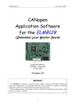
user manual & reference
v2.7, 19 August 2011
Henk Boterenbrood
NIKHEF, Amsterdam, NL
ABSTRACT
Each ATLAS MDT muon chamber is equipped with an MDT-DCS module. The module has
been designed to monitor the chamber's environmental parameters, i.e. temperature (NTC
sensors), magnetic field (B-field sensors) and front-end electronics parameters (CSM and
Mezzanine Board voltages and temperatures), as well as to initialize and configure the MDT
chamber’s front-end electronics on the CSM and Mezzanines Boards. The heart of the module
is the general-purpose ELMB plug-on microcontroller board with CAN interface for communication. This document gives a detailed description of the MDT-DCS module and its ELMB
application firmware including the CANopen communication protocol and CANopen Object
Dictionary.
1
v2.7 19-Aug-2011
MDT-DCS CANopen module
Table of Contents
1
INTRODUCTION AND OVERVIEW............................................................................. 4
2
HARDWARE...................................................................................................................... 6
2.1
2.2
CONNECTORS AND INTERFACES ................................................................................................ 6
ELMB / MDT-DCS INTERFACE AND ELMB JUMPERS ........................................................... 10
3
INITIALISATION ........................................................................................................... 12
4
NODE GUARDING AND LIFE GUARDING.............................................................. 13
5
MDT ON-CHAMBER SENSORS MONITORING...................................................... 15
5.1 DATA READ-OUT ..................................................................................................................... 15
5.2 T-SENSOR READ-OUT .............................................................................................................. 16
5.2.1
T-sensor Data................................................................................................................... 16
5.2.2
ADC Data Conversion ..................................................................................................... 18
5.2.3
ADC Raw Data................................................................................................................. 19
5.2.4
Readout-on-Change ......................................................................................................... 19
5.3 B-SENSOR READ-OUT .............................................................................................................. 21
5.3.1
B-sensor Data................................................................................................................... 21
5.3.2
ADC Data Conversion ..................................................................................................... 22
5.3.3
B-sensor Serial Number ................................................................................................... 23
6
CSM FRONT-END ELECTRONICS MONITORING AND CONTROL................. 25
6.1 ANALOG INPUTS ...................................................................................................................... 25
6.1.1
Readout-on-Change ......................................................................................................... 26
6.2 CONFIGURATION AND CONTROL ............................................................................................. 27
6.2.1
JTAG ................................................................................................................................ 27
6.2.1.1
6.2.1.2
6.2.1.3
6.2.1.4
6.2.1.5
6.2.1.6
6.2.2
7
Implementation Overview.......................................................................................................................... 27
JTAG-action Storage.................................................................................................................................. 29
Examples of MDT-DCS JTAG Operations................................................................................................ 29
JTAG TAP States....................................................................................................................................... 36
JTAG Signal Timing .................................................................................................................................. 36
Additional JTAG Functionality.................................................................................................................. 37
Digital I/O ........................................................................................................................ 37
CONFIGURATION STORAGE .................................................................................... 39
7.1
7.2
7.3
STORING PARAMETERS AND SETTINGS ................................................................................... 39
AUTO-CONFIGURE ................................................................................................................... 40
EEPROM MEMORY MAP ........................................................................................................ 41
8
UPGRADING THE FIRMWARE.................................................................................. 43
9
MDT-DCS OBJECT DICTIONARY ............................................................................. 44
10 EMERGENCY OBJECTS .............................................................................................. 64
11 BUILT-IN BOARD TEST ............................................................................................... 66
REFERENCES........................................................................................................................ 69
APPENDIX A.
MDT-DCS MOTHERBOARD SCHEMATIC ....................................... 70
APPENDIX B.
NTC TEMPERATURE SENSOR DATA ............................................... 71
2
v2.7 19-Aug-2011
MDT-DCS CANopen module
Version History
Version Date
Comments
2.7
19 Aug 2011
• Describes firmware version "MD25", minor version "0000".
• Added subindex 22 to Object 2201h, ADC-config CSM:
mezzanine mask.
• Added ‘during latch’ item to ADC conversion time-out Emergency.
• Two additions to Object 2500h, B-sensor ADC configuration.
2.6
8 Mar 2008
• Some minor modifications to the text.
2.5
21 Aug 2007
2.4
22 Jun 2006
2.3
3 Aug 2005
2.2
27 May 2004
2.1
16 Jan 2004
2.0
17 Nov 2003
1.0
30 May 2002
Table 1.
• Describes firmware version "MD24", minor version "0001".
• PDOs for JTAG can have any number of bytes between 2 and 8 (instead of previously exactly 5).
• Added Objects 4831h and 4832h, for setting the JTAG state after a
SHIFT_IR or SHIFT_DR operation.
• Describes firmware version "MD24", minor version "0000".
• Added info on CSM+Mezz temperature sensors.
• Created separate sections for T and B data conversion.
• MDT-DCS module schematics added.
• Various minor changes, corrections and additions.
• Added Objects 480Ch, 480Dh, 49XCh, 49XDh and 49XEh.
• Describes firmware version "MD24", minor version "0000".
• Added description and objects for JTAG string uploading and
downloading by means of the Segmented SDO protocol.
• Added description of ‘autoconfigure’ capability.
• Added pictures of production acceptance test setup.
• Corrected wrong values for the reference T-sensors 30 and 31.
• Various minor changes to text.
• Describes firmware version "MD23".
• JTAG action storage, actions and sequences implemented.
• 'Readout-on-delta-change' feature added for T-sensors and
CSM analog inputs.
• Support for remotely configurable Node-ID added.
• Presence of B-sensor modules now controlled by a mask.
• PDO event timers now in seconds (instead of ms) and active for all
transmission types.
• Digital Out power-up setting now on individual bit basis.
• Another update of the section on board testing.
• Up-to-date pictures of frontpanels ('Barrel' as well as 'EndCap').
• Describes firmware version "MD22".
• Support for up to 4 B-sensor modules, instead of 2, as before.
• Support for 'raw' T-sensor data readout.
• JTAG TDI and TDO signals swapped.
• Does not yet support JTAG-action strings storage.
• Update of the section on board testing.
• Describes firmware version "MD21".
• Does not yet support JTAG-action strings storage.
• Added this document change record.
Describes firmware version "MD14" (and older),
for the MDT-DCS module prototype equipped with ELMB103 modules.
Document change record.
3
v2.7 19-Aug-2011
MDT-DCS CANopen module
1 Introduction and Overview
The MDT-DCS module is the local monitor-and-control platform for the ATLAS MDT
muon chambers. It is based on the ELMB 1 module, which is a general-purpose plug-on board
which was developed by the ATLAS collaboration to serve various detector control tasks in
and around the ATLAS detector. The ELMB is also used in several applications outside the
ATLAS environment, in other LHC experiments and at CERN. The ELMB features an insystem-programmable microcontroller, a CAN-bus controller and interface for communication with a host system and/or the central SCADA system, and a number of analog inputs and
digital in- and outputs. It is in-system-programmable, including remotely, via the CAN-bus.
The latter combined with the ELMB’s low cost and the availability of a low cost development
environment for programming in C, have all contributed to its success. For its application in
ATLAS the fact that its radiation tolerance/sensitivity has been extensively tested and quantified is very important.
In the MDT muon subdetector of ATLAS the MDT-DCS module monitors MDT chamber
environmental parameters, i.e. temperature and magnetic field in and around the chamber, and
MDT front-end electronics voltages and temperatures. The MDT front-end electronics consist
of the so-called CSM (Chamber Service Module) plus connected Mezzanine Boards.
The MDT-DCS module has a JTAG interface, that connects to the CSM, for configuration of
the MDT front-end electronics. In addition there are a number (7) of Digital I/Os for control
output to the CSM and error status input from the CSM.
The CAN bus is the chosen fieldbus by the ATLAS Detector Control System (DCS) for interconnecting distributed I/O within the detector. The CANopen protocol [2] [3] has been
adopted as the communication protocol standard to be used on the CAN-bus.
The application firmware running on the ELMB inside the MDT-DCS module complies
where possible with the CANopen DS-401 Device Profile for I/O-modules [4], but it has a
range of additional 'manufacturer-specific' Object Dictionary entries and configuration options. The complete Object Dictionary (OD) of the MDT-DCS CANopen node can be found in
section 9.
The MDT-DCS firmware development is based on a framework provided by the so-called
ELMBio application firmware described in [1].
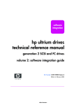
A simplified block diagram of an MDT-DCS module mounted on an MDT muon chamber,
and its connections to sensors and front-end electronics is shown in Figure 1. There are connections to the on-chamber T- (temperature) and B-sensors (magnetic field), and (multiple)
connections to the MDT front-end electronics.
The T-sensors are NTC resistors (for Barrel MDT chambers) integrated in special cables and
mounted on various locations on the MDT chamber.
Each B-sensor module measures the magnetic field along 3 orthogonal axes (Bx, By and Bz)
and the temperature (T) of the environment in the immediate vicinity of the 3 Hall-effect
transducers, which are mounted on the B-sensor module PCB. By using special cables the
number of connected B-sensor modules may be increased from 2 to 4 per MDT-DCS module.
1
see http://elmb.web.cern.ch/
4
v2.7 19-Aug-2011
MDT-DCS CANopen module
Figure 1. Block diagram of the MDT-DCS module with ELMB, its connections to the
MDT front-end electronics and the external sensors (for temperature and Bfield), mounted on an MDT chamber. Although originally intended to support two Magnetic Field Sensor modules, this number may be increased to
four per MDT-DCS module using special cables (see section 5.3).
5
v2.7 19-Aug-2011
MDT-DCS CANopen module
2 Hardware
2.1
Connectors and Interfaces
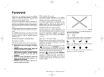
Figure 2 shows the front panel of the MDT-DCS module with its external interfaces. There
are 2 types of MDT-DCS modules, a 'Barrel' type and an 'Endcap' type, which visibly only
differ by their labels as shown in Figure 2. The 'Endcap' type is equipped for voltage-based Tsensors (such as PT1000), and the 'Barrel' type for resistance-type T-sensors (NTC); the firmware has been preconfigured accordingly.
JTAG interface
(for CSM configuration)
+ 4x Digital I/O
connectors for
NTC temperature
sensors
NTC #14
connector
GND
CAN
connectors
CAN Node Identifier
(address) of this module
+5V
MDT-DCS
module
Serial
Number
NTC #29
connector
B-sensor
pin 1
B-sensor
connectors
Label with ATLAS number/barcode
on the side of the MDT-DCS box
SPI interface
to ADC on CSM
+ 3x Digital I/O
spare digital interface
(e.g. for SPI or JTAG, to be
implemented in software)
MDT-DCS module 'EndCap' type
indicated by:
• a yellow label
• serial number is
followed by an 'e'
(on label only)
Figure 2. MDT-DCS module front panel connectors and labels.
6
v2.7 19-Aug-2011
MDT-DCS CANopen module
Table 2 to Table 6 detail the pin layout of the MDT-DCS module's JTAG, SPI-AUX, CSMADC and CAN frontpanel connectors.
20
2
Table 2.
20
2
Table 3.
19
1
function
pin
pin
function
comment
GND
20
19
GND
GND
18
17
Dig I/O 4 (PA7)
Reprogram_FPGA*
GND
16
15
Dig I/O 3 (PA6)
Reset_FPGA
+3.3V
14
13
Dig I/O 2 (PA5)
Sel_SW_TDO*
+3.3V
12
11
Dig I/O 1 (PA4)
Sel_HW_TDO*
+3.3V
10
9
TDI
(PA3, in)
JTAG interface
+3.3V
8
7
TMS
(PA2, out)
JTAG interface
GND
6
5
TCK
(PA1, out)
JTAG interface
GND
4
3
TDO
(PA0, out)
JTAG interface
GND
2
1
GND
Layout of the JTAG connector pins: 8 general-purpose digital in- and outputs. In brackets the ELMB microcontroller pin name is shown, in italics the
CSM's name for the signal function.
19
1
function
pin
pin
function
GND
20
19
GND
GND
18
17
not connected
GND
16
15
not connected
+3.3V
14
13
not connected
+3.3V
12
11
Aux I/O
(PC5)
+3.3V
10
9
Aux I/O
(PC4)
+3.3V
8
7
Aux I/O
(PF6)
GND
6
5
Aux I/O
(PC6)
GND
4
3
Aux I/O
(PC7)
GND
2
1
GND
Layout of the SPI-AUX connector pins: 5 general-purpose Digital I/Os, sufficient and suitable for implementing a serial interface like SPI, I2C or JTAG
for instance (to be implemented in the MDT-DCS/ELMB firmware). In
brackets the ELMB microcontroller pin name is shown.
7
v2.7 19-Aug-2011
MDT-DCS CANopen module
20
2
Table 4.
19
1
function
pin
pin
function
GND
20
19
GND
GND
18
17
Dig I/O 7 (PF4)
GOL | TTC
Not Ready
GND
16
15
Dig I/O 6 (PF3)
I2C Error
+3.3V
14
13
Dig I/O 5 (PF2)
CSM Error
+3.3V
12
11
MUX
(PE7, out)
for ADC
+3.3V
10
9
CS
(PC3, out)
for ADC
+3.3V
8
7
SDO
(PE6, in)
for ADC
GND
6
5
SDI
(PE5, out)
for ADC
GND
4
3
SCLK
(PE4, out)
for ADC
GND
2
1
GND
Layout of the CSM-ADC connector pins: SPI serial interface (SCLK, SDI
and SDO) with Chip-Select (CS) and ADC-multiplexer latch signal (MUX) go
to the ADC on the CSM (which has a copy of the ELMB’s on-board ADC circuitry). In addition there are 3 general-purpose Digital I/Os. In brackets the
ELMB/microcontroller pin name is shown, in italics the CSM's description
for the signal function.
function
Table 5.
comment
pin
pin
function
1
not connected
CAN-GND
6
2
CAN-L
CAN-H
7
3
CAN-GND
+VAP (6-12V)
8
4
AGND
CAN-POWER (8-12V)
9
5
CAN-SHIELD
Layout of the CAN connectors pins; there are 2 connectors on each MDTDCS module for easy daisy-chaining multiple modules on one CAN-bus. All 9
pins of both connectors are 1-to-1 connected. CAN-POWER powers the CANdriver part of the ELMB. +VAP powers both digital and analog parts of the
ELMB. CAN-SHIELD is not connected to the MDT-DCS module internally.
Pins 3 and 5 (CAN-GND) are connected internally; if only one pin is connected externally in the cable it must be pin 3 (CANopen cable definition).
The MDT-DCS module's serial number can be read out remotely (actually it is the serial
number of the ELMB module inside; this means the ELMB inside should not be exchanged!).
The module's CAN node identifier is stored in ELMB EEPROM (so not set by means of the
ELMB's dip-switches) and can be changed remotely, if necessary.
8
v2.7 19-Aug-2011
MDT-DCS CANopen module
pin 1
Pin
Function
1
2
3
4
5
6
7
8
9
10
SCLK
GND
SDI
GND
SDO
GND
CS
ID
–
V+
Table 6.
3x Hall sensor
10
Comment
SPI Serial Clock (to ADC)
SPI Serial Data In (to ADC)
SPI Serial Data Out (from ADC)
Chip Select (to ADC)
1-Wire interface (to ID-chip)
from CAN-connector (pin 8)
Layout of the B-sensor module connector pins.
NTC thermistor
ADC
NTC thermistor inside
ID-chip
pin 1
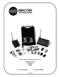
Figure 3. Left:
MDT-DCS B-sensor module and cable.
Right: T-sensor cable with integrated NTC thermistor.
Figure 3 shows some images with details of the B-sensor module and temperature sensor.
9
v2.7 19-Aug-2011
MDT-DCS CANopen module
The module has 2 CAN-bus connectors to enable easy daisy chaining of multiple modules
on one CAN-bus. The last module on the bus must be equipped with a termination resistor
(120 Ω, or 180 Ω in the Y-shaped bus layout used for MDT CAN-buses), using a special cable-less connector with the terminator installed inside the connector housing, which is then
plugged into the empty CAN-connector of the last module on the bus.
2.2
ELMB / MDT-DCS Interface and ELMB Jumpers
This section describes how the ELMB board inside the MDT-DCS module interfaces hardware-wise to the rest of the system, and explains the function of the jumpers and switches present on the ELMB. It is given here for reference only.
Table 7 shows the mapping of I/O-pin-to-function of the ATmega128 microcontroller on the
ELMB inside the MDT-DCS module:
•
•
•
•
•
ADC_xxx is the SPI interface for the ELMB on-board ADC with monitors up to 64
channels of MDT-chamber T-sensors (NTCs).
AUX_IO is the spare interface with 5 digital I/O lines (function to be defined; not
yet under control of the firmware); present on module connector labelled
SPI-AUX.
B_xxx
is the SPI interface including two chip-select lines (B_CSx) and 2 lines
carrying the 1-Wire protocol for the Identification-chips (B_IDx), for up
to 2 B-sensor modules on the MDT-chamber; present on module connectors labelled B-sensor 0 and B-sensor 1.
CSM_xxx is the SPI interface to the CSM front-end electronics ELMB-ADC which
monitors up to 64 parameters; present on module connector labelled
CSM-ADC.
DIGIOx are digital in- and outputs from/to the CSM front-end electronics (exact
function still to be defined; the firmware assumes a default configuration
of inputs and outputs, but this can be changed; see Object Dictionary);
present on module connectors labelled JTAG and CSM-ADC.
10
v2.7 19-Aug-2011
MDT-DCS CANopen module
I/O PORT:
Function:
pin 0
pin 1
pin 2
pin 3
pin 4
pin 5
pin 6
pin 7
A
B
C
D
E
F
In/Out
TDI
TCK
TMS
TDO
DIGIO1
DIGIO2
DIGIO3
DIGIO4
In/Out
x
SCLK
SDI
SDO
x
x
x
x
In/Out
B_CS0
B_CS1
In/Out
x
x
x
B_SDI
ADC_SCLK
ADC_SDI
ADC_SDO
ADC_MUX
In/Out
x
x
x
B_SCLK
CSM_SCLK
CSM_SDI
CSM_SDO
CSM_MUX
I/O/ADC
B_ID0
B_ID1
DIGIO5
DIGIO6
DIGIO7
CSM_CS
AUX_IO1
AUX_IO2
AUX_IO3
AUX_IO4
AUX_IO5
B_SDO
Table 7. I/O-pin functions of the ELMB microcontroller (ATmega128) on the MDT-DCS module:
x
= NOT available externally (used internally by ELMB).
SCLK/SDI/SDO = lines carrying SPI-protocol for the on-board CAN-controller.
(see text above for explanation of other signals).
Greyed out pin identifiers are not implemented in the MDT-DCS ELMB firmware (yet).
Using the ELMB's onboard DIP-switches a node identifier can be set between 1 and 63 (has
to be unique on the CAN-bus the board is connected to), using 6 of the 8 switches, and a
CAN-bus baud rate of 50, 125, 250 or 500 kbit/s, using the 2 remaining switches. See Figure 4
below for details. A label on the front panel shows the node identifier of the MDT-DCS module. Default the baud rate is set to 125 kbit/s.
ELMB top side
Node-ID
(up=0, down=1; shown here = 17)
Bits: 5 4 3 2 1 0
50 kbit/s
125 kbit/s
ATmega
128
1234 5678
250 kbit/s
CAN
baudrate
500 kbit/s
Programmer/RS232 adapter connector
Figure 4. Location and function of ELMB DIP-switches and jumpers.
Note that, starting with MDT-DCS firmware version 2.3, it is possible to configure the node
identifier remotely, i.e. using standard CANopen messages; see objects 3300h and 3301h in
the MDT-DCS Object Dictionary for more details.
Once the Node-ID has been changed through CAN, the DIP-switch setting for the Node-ID
is ignored, and the Node-ID is read from a fixed location in the ELMB's EEPROM. The baud
rate setting is not affected.
NB: this feature should only be used if the ELMB's Bootloader firmware is version 1.3 or later!
11
v2.7 19-Aug-2011
MDT-DCS CANopen module
3 Initialisation
When the MDT-DCS ELMB firmware initialises, all hardware devices are reset and configured (CAN-controller, ADC for the NTCs, ADC on the CSM, the ADCs on the B-sensor
modules, JTAG interface, etc.) and error counters and registers are reset. Digital outputs are
initialised on the occurrence of a hard reset, but not on a soft reset (see below).
After power-up, watchdog reset, manual reset or a CANopen initiated reset action (i.e. by an
NMT Reset-Node message, see below) a CANopen node sends a so-called Boot-up message
(as defined by the CANopen standard) as soon as it has finished initializing (hardware, software); this is a CAN-message with the following syntax:
MDT-DCS module (NMT-Slave)
COB-ID
700h + NodeID
→
Host (NMT-Master)
Data Byte 0
0
NodeID is the CAN node identifier (initially) set by means of the ELMB onboard DIPswitches to a value between 1 and 63, as shown earlier in Figure 4. NodeID must be in the
range between 1 and 127.
To start the MDT-DCS application in the CANopen sense of the word, the following
CANopen NMT message must be sent:
Host (NMT-Master) → MDT-DCS module (NMT-Slave)
COB-ID
000h
Data Byte 0
01h
(Start_Remote_Node)
There is no reply to this message.
Data Byte 1
NodeID or 0
(0: all nodes on the bus)
Now the MDT-DCS module is Operational, meaning that it monitors I/O channels (depending on configuration) and can send and receive (and processes) CANopen PDO messages,
which carry the application data (see next sections).
Optionally a feature called auto-start may be enabled, so that the MDT-DCS module automatically goes to Operational state after power-up or reset. The auto-start feature can be configured in OD index 3200h, subindex 2.
To generate a soft reset the following CANopen NMT message must be sent:
Host (NMT-Master) → MDT-DCS module (NMT-Slave)
COB-ID
000h
Data Byte 0
81h
(Reset_Node)
Again, there is no reply to this message.
Data Byte 1
NodeID or 0
(0: all nodes on the bus)
12
v2.7 19-Aug-2011
MDT-DCS CANopen module
Note that at power-up it is the Bootloader application firmware that becomes active first and
is in control of the MDT-DCS module; the Bootloader reports its presence by sending the following Emergency message (see also section 8):
Bootloader
COB-ID
080h +
NodeID
→
Host
Byte 0-1
Emergency
Error Code
(00h 50h)
Byte 2
Error Register
(Object 1001h)
(80h)
Byte 3-7
Manufacturer specific error field
(FEh 01h 28h ZZh 00h)
(ZZh = MCUCSR)
(MCUCSR = MCU Control and Status Register; for details see section 10 or the ATmega128
datasheet).
Having the Bootloader activate at power-up guarantees that it is always possible to upload
new application software to the ELMB, even when the application currently programmed in
the ELMB is faulty or corrupted.
After about 4 s the Bootloader automatically jumps to the application. Alternatively, the
Bootloader starts the application immediately, if it receives an NMT Reset-Node message –as
shown above- within this period.
4 Node Guarding and Life Guarding
Node Guarding in CANopen is a mechanism whereby an NMT-master checks the state of
other nodes on the bus, at regular intervals. It can do this in one of two different ways:
1. The master sends a Remote Transmission Request (RTR) for the Node Guard message,
to each node on the bus, in turn; a node that receives the RTR, sends the Node Guard
message, which contains one data byte indicating the (CANopen) state of the node, as
well as a toggle bit. If a node does not reply the master should signal this to the higherlevel software and/or take appropriate action.
The RTR for the Node Guard message looks like this (a Remote Frame, so the CANmessage has no data bytes):
Host (NMT-Master)
→
MDT-DCS module (NMT-Slave)
COB-ID
700h + NodeID
The reply Node Guard message from a node looks like this:
MDT-DCS module (NMT-Slave)
COB-ID
700h + NodeID
→
Host (NMT-Master)
DataByte 0
bit 7: toggle bit,
bit 6-0: state
2. Each node on the bus sends a Heartbeat message at regular intervals; typically, the
NMT-master monitors these messages and keeps a time-out period for each node. The
master detects nodes that stop sending their Heartbeat messages and should signal this
to the higher-level software and/or take appropriate action.
13
v2.7 19-Aug-2011
MDT-DCS CANopen module
A Heartbeat message looks like this:
MDT-DCS module (Heartbeat producer)
COB-ID
700h + NodeID
→
Consumer(s) (e.g. NMT-Master)
DataByte 0
state
State is one of these CANopen states: 0 (Initializing), 4 (Stopped), 5 (Operational) or 127
(Pre-operational). Note that this makes the Boot-up message the first Heartbeat message after
a node reset (see previous section).
According to the CANopen standard, a node is not allowed to support both Node Guarding
and Heartbeat protocols at the same time. The MDT-DCS module supports both methods of
Node Guarding (but indeed not at the same time), i.e. it can send the Node Guard message or
it can send the Heartbeat message with an interval, which is configurable in OD index 1017h.
Life Guarding in CANopen is a mechanism whereby a node checks the aliveness of the host
or master, by applying a time-out on messages received. CANopen defines that the message to
time-out is the RTR for the Node Guard message, sent by the NMT-master; however, the
MDT-DCS module resets its Life Guarding timer at each properly received message addressed to it.
Life Guarding is controlled through OD objects 100Ch and 100Dh. In the MDT-DCS module the Life Guarding time-out can be set between 1 and 255 seconds, by setting OD index
100Dh to the corresponding value, or can be switched off, by setting OD index 100Dh to zero.
If a Life Guarding time-out occurs, the node should take whatever appropriate action. The
MDT-DCS module resets and reinitializes the CAN-controller, and (tries to) resume(s) normal
operation, after sending an Emergency message (see section 10).
14
v2.7 19-Aug-2011
MDT-DCS CANopen module
5 MDT On-Chamber Sensors Monitoring
5.1
Data Read-out
Each data object in the MDT-DCS module can be accessed through the CANopen Object
Dictionary (OD). The CANopen SDO (Service Data Object) confirmed message mechanism
is used to read from and write to data objects in the OD.
A complete overview of the Object Dictionary of the MDT-DCS module can be found in
section 9.
A more efficient method of read-out of data from the MDT-DCS module is offered by the
CANopen mechanism of PDO (Process Data Object) messages. This is an unconfirmed message mechanism without protocol overhead, and thus much more suitable for regular monitoring of the process data of the MDT-DCS module, such as the T- and B-sensor data. The sending of this type of messages may be triggered by a host system or autonomously by the MDTDCS module firmware.
From the point of view of the MDT-DCS module data are transmitted by a PDO message,
called a Transmit-PDO (or TPDO), and data are received in a PDO message, called a Receive-PDO (or RPDO). In CANopen the CAN-identifier, message content and transmission
type of PDO messages may be configurable (configure by writing to the appropriate objects in
the Object Dictionary using the SDO mechanism).
However, the CANopen standard defines a predefined set of CAN-identifiers (the so-called
Predefined Connection Set), defining which CAN-identifier to use for which kind of
CANopen message, without the need for the node to support configuration. The MDT-DCS
module uses this set of identifiers. Also the PDO message content is fixed in the MDT-DCS
module and cannot be changed. The content of PDO messages can be found and read from the
OD from objects called PDO mapping objects (stored at fixed entries in the OD).
A feature that is configurable on the MDT-DCS module is the so-called transmission type
of the TPDOs, which controls what triggers it to send its 'process' data, e.g. periodically, on
request or on-change. For each of the monitored subsystems (T, B, front-end) this is described
in the sections following.
Serious problems occurring during read-out, e.g. with the ADC hardware, are reported in socalled CANopen Emergency messages. A list of Emergency messages the MDT-DCS module
can generate can be found in section 10, including a description of the problem.
15
v2.7 19-Aug-2011
MDT-DCS CANopen module
5.2
T-sensor Read-out
5.2.1 T-sensor Data
T-sensor data is produced by the MDT-DCS module in the form of temperature readings in
millidegrees centigrade of the NTC sensors (optionally as resistance values in Ohms). Evennumbered ADC channels measure the voltage across an NTC and odd-numbered channels the
voltage resulting from the corresponding current through a precision resistor. A division results in the NTC resistance value, which is then converted to a temperature (see end of this
section for the conversion formula used) and sent in a CAN-message by the module.
The MDT-DCS module sends one PDO message containing 4 bytes for every T-sensor. The
CAN-identifier used for this PDO is the so-called 2nd-transmit-PDO (TPDO2) of the
CANopen Predefined Connection Set.
The number of T-sensors read out can be set by configuring the number of analog channels
to any value up to 64 by writing to OD index 2100h, subindex 1. The number of T-sensors
read out is this number divided by 2 (due to the two-analog-inputs measurement per sensor).
“T-sensor” number 30 and 31 are in fact onboard reference resistors (of 16369 Ω and
341.6 Ω, representing temperatures of 0.0°C and 100.0°C, respectively) whose values may be
read out to check the proper functioning of module and ADC.
The setting of OD index 4400h determines whether the readings in the PDO messages are in
Ohms or in millidegrees centigrade. The default setting is degrees.
The MDT-DCS module produces a 4-databyte TPDO2 per T-sensor formatted either (when
OD index 4400h is set to 1) as:
MDT-DCS module
COB-ID
280h + NodeID
with:
Temperature:
NTC number:
→
Host
Data Byte 0
NTC number
Data Byte 1-3
Temperature [m°C]
24-bits temperature reading in millidegrees centigrade, LSB in byte 1,
MSB in byte 3; invalid readings and ADC errors result in a temperature value of FFFFFFh (16777215).
Number between 0 and 29.
or formatted (when OD index 4400h is set to 0) as:
MDT-DCS module → Host
COB-ID
Data Byte 0
Data Byte 1
Data Byte 2-3
280h + NodeID
NTC number
Status + ADC-config
Resistance [Ω]
with:
Resistance:
16-bits NTC resistance value in Ω, LSB in byte 2, MSB in byte 3.
NTC number:
Number between 0 and 29.
Status+ADC-config: bit 7: Conversion status: 1=ERROR (overflow or oscillation occurred
during at least one of the two ADC conversions), 0=OKAY.
bits 6-0: ADC configuration: conversion word rate (bits W0, W1 and
16
v2.7 19-Aug-2011
MDT-DCS CANopen module
W2), gain range (bits G0, G1 and G2) and unipolar or bipolar (bit U/B);
see below. For definitions see OD index 2100h, sub 2, 3 and 4.
BIT
Meaning
7
Error
6
W2
5
W1
4
W0
3
G2
2
G1
1
G0
0
U/B
The method by which all 30 (or less) T-sensors is read out depends on the transmission-type
of TPDO2, which can be set by the user to the required value by writing to OD index 1801h,
subindex 2 of the MDT-DCS module. The value may be stored in onboard EEPROM permanently, so that it will be the default transmission type after every subsequent reset or powerup. The default value before configuration can be found in the OD listing in section 9.
The following modes of TPDO2 transmission are supported (see OD index 1801h, subindex
2 and 5:
•
PDO transmission type 1:
after every so-called SYNC message issued on the CAN-bus the MDT-DCS module
starts an analog input channel scan and sends (up to) 32 TPDO2 messages, one message
for every T-sensor. Two A/D conversions have to be done for every T-sensor so it can
take up to about 30 seconds before all TPDO2s have been sent, depending on how the
ADC has been configured (the ADC conversion rate can be as low as 1.88 Hz).
The SYNC message is a CAN-message with a fixed COB-ID and no data bytes:
Host
→
all (SYNC-)slave nodes
COB-ID
080h
Note that all nodes that have PDOs configured to respond to a SYNC message will respond to the SYNC, which is a broadcast message.
•
PDO transmission type 255:
after every so-called Remote Transmission Request (RTR) for TPDO2 the MDT-DCS
module starts an analog input channel scan and sends (up to) 32 TPDO2 messages, one
message per T-sensor. The Remote Frame CAN-message that constitutes this RTR has
no data bytes and looks like this:
Host
→
MDT-DCS module
COB-ID
280h+NodeID
Note that an RTR is sent to and received/processed by only one particular node.
•
Event Timer > 0:
If TPDO2’s event timer (OD index 1801h, sub 5) is set to a value unequal to zero (event
timer is expressed in units of 1 s and must be <=255) the MDT-DCS module automatically starts an analog input channel scan (resulting in up to 32 TPDO2 messages, one
message per T-sensor) periodically, triggered by a timer (in this mode an RTR or SYNC
message also triggers an input scan, depending on the transmission mode as shown
above). Also see section 5.2.4.
17
v2.7 19-Aug-2011
MDT-DCS CANopen module
Optionally a reset and calibration sequence can be done before each ADC channel scan. This
feature can be enabled via OD index 2300h (useful perhaps for increasing radiation tolerance).
Individual T-sensors resistance values can be read out using CANopen SDO messages by
reading from OD index 4000h.
Individual T-sensors temperature values can be read out using CANopen SDO messages by
reading from OD index 4010h.
Individual analog inputs (as used in the T-sensor readout) can be read out using CANopen
SDO messages by reading from OD index 6404h (in ADC counts) or from OD index 4300h
(in microvolts). Note that the data in objects 6404h and 4300h contain a 'flags' byte (generated
by the ADC), which is formatted as follows:
BIT
Value
7
1
6
1
5
1
4
0
3
CI1
2
CI0
1
OD
0
OF
with CIn = Channel Indicator bits, indicating which CS5523 ADC physical channel (1 to 4,
coded as 00, 01, 10 and 11, respectively) is used, OD = Oscillation Detect Flag bit and OF =
Over-range Flag bit.
5.2.2 ADC Data Conversion
The MDT-DCS T-sensor is an NTC, Thermometrics type number DC95F502W, with a
nominal resistance of 5 kΩ. See Appendix B for datasheet and temperature data of the NTC.
Voltage UV across the NTC on ADC-channel 2*n is measured, then the current through the
NTC is measured by measuring voltage UI which the current generates across a 10 kΩ resistor
(± 1%) on ADC-channel 2*n+1. With the ADC set to 2.5V unipolar range, the conversion
from raw ADC counts A2n and A2n+1 to resistance value RNTC of T-sensor n is done by:
RNTC = UV/(UI/104) = 104((2.5*A2n)/0xFFFF)/((2.5*A2n+1)/0xFFFF)) = 104A2n /A2n+1
To calculate temperature T (in ºC, in the range from 0 to 100 ºC) of the NTC from NTC resistance value RNTC (in Ω), the following approximation equation (see Appendix B) is used:
T = ( 1.0 / (a + b ln(r) + c ( ln(r) )2 + d ( ln(r) )3 ) ) - 273.15
with r = RNTC/5000,
and a = 3.3540154E-03
b = 2.5627725E-04
c = 2.0829210E-06
d = 7.3003206E-08
when 3.274 >= r > 0.36036
(i.e. when 0º C <= T < 50º C),
or
a = 3.3539264E-03
b = 2.5609446E-04
c = 1.9621987E-06
d = 4.6045930E-08
when 0.36036 >= r >= 0.06831 (i.e. when 50º C <= T <= 100º C).
The conversion functions above are applied by the MDT-DCS firmware to the ADC readings when temperature read-out is set to millidegrees centigrade, which is the default.
18
v2.7 19-Aug-2011
MDT-DCS CANopen module
5.2.3 ADC Raw Data
Starting with MDT-DCS firmware version 2.2, it is possible to configure the TPDO2 containing the T-sensor ADC data, as described in the previous section, such that each PDO message contains an individual analog input conversion value (in ADC counts), i.e. the PDO message contains an object from OD index 6404h.
Note:
− this mode is the default mode of read-out of the socalled EndCap-type of MDT-DCS
modules, where the NTCs have been replaced by voltage-based T-sensors (plus additional circuitry); the host system does the conversion to temperature units.
− read-out in this mode results in calibrated values, because the ELMBs have calibration constants stored onboard for every possible voltage-range; the constants are applied by the firmware, so the conversion from ADC-counts to voltage –by the host
system– is straightforward (for example: in 2.5V unipolar mode, an ADC conversion
count of 65535 corresponds indeed to 2.5V).
When OD index 4401h is set to 1, the MDT-DCS module produces a 4-databyte TPDO2
formatted as follows:
MDT-DCS module → Host
COB-ID
Data Byte 0
Data Byte 1
Data Byte 2-3
280h + NodeID
Channel number Status + ADC-config
ADC count
with:
ADC count:
16-bits ADC count, LSB in byte 2, MSB in byte 3.
Channel number:
Number between 0 and 63 (ADC input channel number).
Status+ADC-config: bit 7: Conversion status: 1=ERROR (overflow or oscillation), 0=OKAY.
bits 6-0: ADC configuration: conversion word rate (bits W0, W1 and
W2), gain range (bits G0, G1 and G2) and unipolar or bipolar (bit U/B);
see above. For definitions see OD index 2100h, sub 2, 3 and 4.
5.2.4 Readout-on-Change
Starting with MDT-DCS firmware version 2.3.1 a so-called 'readout-on-change' feature was
added. It means that the MDT-DCS module automatically and periodically scans the T-sensor
channels and sends a message (a TPDO2) only for a T-sensor that changed its value with a
preset minimum value (the 'delta'). This delta value is one of the ADC's configuration parameters, and can be set to any value. There is one delta that applies to all T-sensor channels.
To enable this feature for the T-sensors:
• set the TPDO2 event timer (Object 1801h, sub 5) to a value > 0: this will be the period (in seconds) between two consecutive T-sensor channel scans,
• set the T-sensor ADC delta value (Object 2100h, sub 22) to a value > 0,
• set the MDT-DCS module to Operational.
19
v2.7 19-Aug-2011
MDT-DCS CANopen module
The first scan cycle does not produce any output, but the T-sensors are read out, and the
readings are used as reference values to detect a 'delta' change in any of the values in subsequent channel scans. As soon as this occurs the value is sent and taken as the new reference
for the channel that changed.
At any time a host system may request a read-out of all T-sensors by sending a SYNC or
RTR message to the MDT-DCS module; it does not influence the 'scan-for-change' feature,
although an ongoing T-sensor channel scan is aborted; current T-sensor reference values are
not changed by this action. A next channel scan is automatically started when the timer expires again.
If the TPDO2 event timer is set to a value > 0, but delta is set to 0, the 'normal' procedure of
read-out takes place: every n seconds all T-sensors are read out and their values sent in messages, as described in section 5.2.1.
Note that TPDO event timer triggered readout takes place only when the node is in Operational state.
Note that the delta value is always taken to be in the units in which read-out currently takes
place, i.e. millidegrees, Ohms or raw ADC-counts. So if you change your unit of read-out, the
delta value itself does not change, but its unit does !
20
v2.7 19-Aug-2011
MDT-DCS CANopen module
5.3
B-sensor Read-out
By writing to OD index 2800h, none, or up to four B-sensor modules can be selected, in the
form of a bit mask, i.e. if OD index 2800h has value Fh, all four B-sensor modules are present). The default is: no B-sensor module present, OD index 2800h has value 0 (zero).
The MDT-DCS module has originally been designed to read out up to two B-sensor modules
only. In case three or four B-sensor modules are connected to one MDT-DCS module, they
must be connected to a cable in pairs, as illustrated in Figure 5. The module numbering is
fixed and is as shown in Figure 5.
MDT-DCS
B-sensor 1
B-sensor 0
B-sensor #0
B-sensor #2
B-sensor #1
B-sensor #3
pin 7 and 8 wires to be swapped
on the connector of the second
B-sensor module on the cable
Figure 5. Connecting more than two B-sensor modules to one MDT-DCS module.
(Note: the cable shown in the picture is of a type not approved for ATLAS !)
5.3.1 B-sensor Data
The MDT-DCS module sends one PDO message containing 5 bytes for each B-sensor input
and per B-sensor module 4 inputs are read: Hall sensors H1, H2 and H3 and the temperature
sensor. The CAN-identifier used for this PDO is the so-called 4th-transmit-PDO (TPDO4) of
the CANopen Predefined Connection Set.
The MDT-DCS module produces the following 5-databyte TPDO4:
MDT-DCS module
COB-ID
480h + NodeID
with:
ADC value:
Channel number:
→
Host
Data Byte 0
Channel number
Data Byte 1
ADC-config
Data Byte 2-4
24-bit ADC value
Signed/unsigned 24-bits ADC value, LSB in byte 2, MSB in byte 4.
Note: Hall sensors: 24-bit signed value; T-sensor: 24-bit unsigned value
(either an ADC count or a temperature in millidegrees centigrade depending on the setting of OD index 4400h),
Number between 0 and 15.
Chan 0-3: Hall sensor H1, H2, H3 and T-sensor resp. of B-sensor #0,
21
v2.7 19-Aug-2011
MDT-DCS CANopen module
ADC-config:
BIT
Meaning
Chan 4-7: Hall sensor H1, H2, H3 and T-sensor resp. of B-sensor #1.
Chan 8-11: Hall sensor H1, H2, H3 and T-sensor resp. of B-sensor #2.
Chan 12-15: Hall sensor H1, H2, H3 and T-sensor resp. of B-sensor #3.
bit 7: not used.
bits 6-0: ADC configuration: conversion word rate (bits W0, W1 and W2),
gain range (bits G0, G1 and G2) and unipolar or bipolar (bit U/B); see below. For definitions see OD index 2500h/2501h, sub 2,3,4,5,6 and 7.
7
-
6
W2
5
W1
4
W0
3
G2
2
G1
1
G0
0
U/B
The method by which the B-sensor module inputs are read out depends on the transmissiontype of TPDO4, which can be set in OD index 1803h, subindex 2 of the MDT-DCS module.
The method options are identical to what has been described for the read-out of the T-sensors
in section 5.2.
Optionally a reset and calibration sequence can be done before each B-sensor ADC channel
scan. This feature can be enabled via OD index 2700h (useful perhaps for increasing radiation
tolerance).
Individual B-sensor module channels (there are actually 7 per module) can be read out using
CANopen SDO messages by reading from OD index 4200h to 4203h (see OD tables for a description of each individual channel).
5.3.2 ADC Data Conversion
The interpretation of the Hall sensor ADC values and conversion to physical values will be
done offline using a set of calibration tables accompanying each individual B-sensor module.
Until these tables are available the user himself must interpret the data.
The B-sensor module's T-sensor is an NTC, Thermometrics type number DC95F502W, with
a nominal resistance of 5 kΩ. See Appendix B for datasheet and temperature data of the NTC.
Table 8 shows a list of resistance values RNTC for this NTC at different temperatures, and
the resulting B-sensor module ADC input voltage. In the shaded part of the table (between 0º
and 70º C) the precision is ±0.2º C.
The ADC input voltage VNTC can be expressed as:
VNTC = Vref - VccRNTC / (RNTC + Rref)
which can be rewritten as:
RNTC = Rref (Vref - VNTC) / (VNTC + Vcc - Vref)
With Rref = 23.2 kΩ, Vcc = 5 V and Vref = 2.5 V this results in:
RNTC = 23200 (2.5 - VNTC) / (VNTC + 2.5)
22
v2.7 19-Aug-2011
MDT-DCS CANopen module
VNTC is the voltage value calculated from the 24-bit ADC value A.
The ADC input has been calibrated to give A=0 (000000h) at 0 ºC (i.e. at 0.4315 V) and
A=16777215 (0xFFFFFF) at 100 ºC (i.e. at 2.4275 V), so that VNTC can be expressed as:
VNTC = 0.4315 + (2.4275 - 0.4315)A/FFFFFFh = 0.4315 + 1.996A/FFFFFFh
So RNTC can be calculated directly from ADC value A as follows:
RNTC = 23200 (2.0685 - a) / (2.9315 + a)
with a = 1.996 A / 16777215.
With RNTC known, the temperature (in ºC) can now be calculated using the equation(s) for T
from the previous section.
The conversion equations described above are applied by the MDT-DCS firmware when
temperature read-out is set to millidegrees centigrade, which is the default setting.
5.3.3 B-sensor Serial Number
Each B-sensor module comes equipped with a unique serial number, which is factorylasered in the on-board Dallas DS2401 device.
The 64-bit (8-byte) serial number is used to uniquely identify each module, for instance, to
match each module with its calibration data, which are stored off-line.
The serial numbers of the four B-sensor modules can be read from OD Objects 2900h,
2901h, 2902h or 2903h. The least significant 4 bytes are read from subindex 1 and the most
significant 4 bytes from subindex 2. Starting with MDT-DCS firmware version 2.4.0 the leastor most-significant sets of 4 bytes can be read in any order.
The layout of the 64-bit serial number is as shown below:
8-bit CRC Code
MSB
LSB
byte 7
48-bit Serial Number
MSB
8-bit Family Code (01h)
LSB
byte 6-4
byte 3-1
↓
↓
OD index 290Xh, subindex 2
MSB
LSB
byte 0
↓
↓
OD index 290Xh, subindex 1
Figure 6. B-sensor 64-bit Serial Number and its mapping to Object Dictionary (OD)
objects (with X=0 to 3).
The MDT-DCS module checks the correctness of the serial number CRC when OD Object
2900h to 2903h is read, so a valid reply implies the CRC was correct: it is not necessary for
the host to recalculate the serial number CRC.
23
v2.7 19-Aug-2011
MDT-DCS CANopen module
[C]
-50
Normalized
Resistance
Ohm
68.60
-45
Temperature
Resistance
AIN4
(ADC)
Volt
Ohm
343000.00
-2.1832
48.16
240800.00
-2.0606
-40
34.23
171150.00
-1.9031
-35
24.62
123100.00
-1.7071
-30
17.91
89550.00
-1.4712
-25
13.17
65850.00
-1.1974
-20
9.782
48910.00
-0.8913
-15
7.339
36695.00
-0.5633
-10
5.558
27790.00
-0.2250
-5
4.247
21235.00
0.1106
0
3.274
16370.00
0.4315
5
2.544
12720.00
0.7294
10
1.992
9960.00
0.9982
15
1.572
7860.00
1.2347
20
1.250
6250.00
1.4389
25
1.000
5000.00
1.6135
30
0.8056
4028.00
1.7603
35
0.6530
3265.00
1.8831
40
0.5326
2663.00
1.9852
45
0.4369
2184.50
2.0697
50
0.3604
1802.00
2.1396
55
0.2989
1494.50
2.1974
60
0.2491
1245.50
2.2452
65
0.2087
1043.50
2.2848
70
0.1756
878.00
2.3177
75
0.1485
742.50
2.3449
80
0.1261
630.50
2.3677
85
0.1075
537.50
2.3868
90
0.09209
460.45
2.4027
95
0.07916
395.80
2.4161
100
0.06831
341.55
2.4275
105
0.05916
295.80
2.4371
Table 8. NTC resistance/temperature table, and resulting B-sensor ADC input voltage
(Normalized resistance table taken from datasheets in Appendix B).
24
v2.7 19-Aug-2011
MDT-DCS CANopen module
6 CSM Front-end Electronics Monitoring and Control
6.1
Analog Inputs
The CSM-SPI connector provides the interface to an ADC, identical to the ADC on the
ELMB (which is used for the NTC temperature sensors on the MDT chamber), integrated in
the CSM front-end electronics, capable of monitoring up to 64 analog input channels on the
CSM. The analog values monitored include:
• Mezzanine analog voltage
• Mezzanine digital voltage
• Mezzanine temperature
• Motherboard 4.5V
• CSM +5Vcc, -5VEE, 3.3V, 2.5V, 1.8V and 1.5V
• CSM temperature
A list of ADC channels and what parameter they represent, is shown in Table 9 below.
ADC ch
0
1
2
3
4
5
6
7
8
9
10
11
12
13
14
15
Table 9.
Source
Mezz 16 Temp
Mezz 16 Analog
Mezz 16 Digital
CSM 2.5V
Mezz 15 Temp
Mezz 15 Analog
Mezz 15 Digital
CSM 1.5V
Mezz 17 Temp
Mezz 17 Analog
Mezz 17 Digital
CSM 2.5V Ref
Half CSM +5VCC
CSM Temp
Half CSM -5VEE
CSM 2.5V Ref
ADC ch
16
17
18
19
20
21
22
23
24
25
26
27
28
29
30
31
Source
ADC ch
32
33
34
35
36
37
38
39
40
41
42
43
44
45
46
47
Mezz 6 Temp
Mezz 6 Analog
Mezz 6 Digital
CSM 3.3V
Mezz 5 Temp
Mezz 5 Analog
Mezz 5 Digital
Mezz 7 Temp
Mezz 8 Temp
Mezz 8 Analog
Mezz 8 Digital
Mezz 7 Analog
Mezz 9 Temp
Mezz 9 Analog
Mezz 9 Digital
Mezz 7 Digital
Source
Mezz 10 Temp
Mezz 10 Analog
Mezz 10 Digital
CSM 1.8V
Mezz 12 Temp
Mezz 12 Analog
Mezz 12 Digital
Mezz 11 Temp
Mezz 14 Temp
Mezz 14 Analog
Mezz 14 Digital
Mezz 11 Analog
Mezz 13 Temp
Mezz 13 Analog
Mezz 13 Digital
Mezz 11 Digital
ADC ch
48
49
50
51
52
53
54
55
56
57
58
59
60
61
62
63
Source
Mezz 0 Temp
Mezz 0 Analog
Mezz 0 Digital
CSM VCC
Mezz 2 Temp
Mezz 2 Analog
Mezz 2 Digital
Mezz 1 Temp
Mezz 4 Temp
Mezz 4 Analog
Mezz 4 Digital
Mezz 1 Analog
Mezz 3 Temp
Mezz 3 Analog
Mezz 3 Digital
Mezz 1 Digital
Mapping of CSM FE-electronics voltages/temperatures to CSM-ADC channels.
A 2.5V reference connected to one of the 64 analog input channels is used to calibrate the
ADC's 5V input range (at each power-up and reset). The input channel number where the
2.5V reference is connected can be selected in OD index 2101h, subindex 19. The default setting is ADC channel 11. When a value > 63 is set, an ADC-internal calibration is done; in that
case only the ADC's 2.5V voltage range would give accurate readings.
The temperature sensor device used on the CSM and Mezzanine cards is the Analog Devices
TMP36 (offset 0.5V, 10 mV/°C, i.e. output = 0.75V @ 25°C, range -40°C to +125°C, accuracy ±2°C). With the ADC set to 5V bipolar range, the conversion from raw ADC count A to
degrees Celcius can be done using:
0.5+0.01*Celcius = Volts or Celcius = 100*Volts-50,
with Volts = 5.0*A/0x7FFF = 5.0*A/32767.0,
this leads to Celcius = 0.01526*A – 50.
25
v2.7 19-Aug-2011
MDT-DCS CANopen module
The MDT-DCS module sends one PDO message containing 4 bytes for every ADC input.
The CAN-identifier used for this PDO is the so-called 3rd-transmit-PDO (TPDO3) of the
CANopen Predefined Connection Set.
The number of analog inputs read out can be set by configuring it to any value up to 64 by
writing to OD index 2101h, subindex 1.
In addition, using subindex 22, which mezzanines’ ADC data actually gets sent in TPDO3
messages can selectively be set: the data from mezzanines not present in the mask are not sent
to the CAN bus (although the conversions of the ADC channels in question still take place), in
order to limit the sending of meaningless data (MDT-DCS firmware version 2.5.0 and later).
The MDT-DCS module produces the following 4-databyte TPDO3:
MDT-DCS module
COB-ID
380h + NodeID
with:
ADC count:
→
Host
Data Byte 0
Channel number
Data Byte 1
Status + ADC-config
Data Byte 2-3
ADC count
16-bits value, LSB in byte 2, MSB in byte 3. Using the default ADC
configuration setttings: value 7FFFh corresponds to +5.0V, value
0000h to 0.0V, and value 8000h to -5.0V (signed 16-bits value).
Channel number:
number between 0 and 63.
Status+ADC-config: bit 7: Conversion status: 1=ERROR (overflow or oscillation), 0=OKAY.
bits 6-0: ADC configuration: conversion word rate (bits W0, W1 and
W2), gain range (bits G0, G1 and G2) and unipolar or bipolar (bit U/B);
see below. For definitions see OD index 2101h, sub 2, 3 and 4.
BIT
Meaning
7
Error
6
W2
5
W1
4
W0
3
G2
2
G1
1
G0
0
U/B
The method by which all (64 or less) analog inputs are read out depends on the transmissiontype of TPDO3, which can be set in OD index 1802h, subindex 2 of the MDT-DCS module.
The options for the transmission-type are the same as described for the read-out of the Tsensors in section 5.2.
Optionally a reset and calibration sequence can be done before each ADC channel scan. This
feature can be enabled via OD index 2301h (useful perhaps for increasing radiation tolerance).
Individual analog inputs can be read out using CANopen SDO messages by reading from
OD index 4100h. Note that the data in objects 4100h contains a 'flags' byte (generated by the
ADC), which is described in section 5.2.1.
6.1.1 Readout-on-Change
Starting with MDT-DCS firmware version 2.3.1 a so-called 'readout-on-change' feature was
added. It means that the MDT-DCS module automatically and periodically scans the CSM
analog channels and sends a message (a TPDO3) only for a channel that changed its value
with a preset minimum value (the 'delta'). This delta value is one of the ADC's configuration
parameters, and can be set to any value. There is one delta that applies to all CSM channels.
26
v2.7 19-Aug-2011
MDT-DCS CANopen module
To enable this feature for the CSM analog inputs, do the following:
• set the TPDO3 event timer (Object 1802h, sub 5) to a value > 0: this will be the period (in seconds) between two consecutive CSM channel scans,
• set the CSM ADC delta value (Object 2101h, sub 21) to a value > 0,
• set the MDT-DCS module to Operational.
For further details see section 5.2.4.
6.2
Configuration and Control
The CSM-ADC, JTAG and SPI-AUX connectors provide interfaces for additional configuration and control of the CSM front-end electronics.
The CSM-ADC connector provides, in addition to the serial interface to an ADC on the CSM
as described in section 6.1, three general-purpose I/Os, which are available as bits 4-6 through
the CANopen mechanism for Digital I/O (see section 6.2.2).
The JTAG connector implements a JTAG host interface and is used to configure the CSM
electronics. In addition, this connector provides four general-purpose I/Os, which are available
as bits 0-3 through the CANopen mechanisms for Digital I/O (see section 6.2.2).
The MDT-DCS firmware does not have any support for the interface provided by the SPIAUX connector. It is spare and may be used to implement extra Digital I/Os or to drive a serial
interface. Appropriate additions to the module's firmware and Object Dictionary would have
to be made and possibly additional PDOs defined, to satisfy the requirements of the task foreseen.
6.2.1 JTAG
6.2.1.1 Implementation Overview
The MDT-DCS module supports 2 methods of uploading a JTAG bit string to the CSM electronics:
1. Relay method: the host system sends the JTAG bit string to the ELMB, in chunks; MDTDCS shifts out each bit string chunk, immediately upon reception, into the JTAG chain.
This method enables upload of arbitrary JTAG bit strings to the CSM.
2. Storage method: the host system sends a single message to trigger the upload of one (actually a pair) from a number of JTAG bit strings permanently stored in the MDT-DCS
module's memory. This method enables fast (compared to the relay method) upload of
any selection in any order of previously stored bit strings to the CSM.
A JTAG bit string contains always either data bits (upload takes place in TAP state ShiftDR), or instruction bits (upload takes place in TAP state Shift-IR).
Usually an instruction bit string is shifted into a JTAG chain, followed by a data bit string;
the combination of such an instruction and data bit string is called here: a JTAG-action.
Upload method 1 supports both instruction and data bit string upload, in chunks of 32 bits
(in principle up to any bit string length), or, in a socalled ‘segmented transfer’ (MDT-DCS
27
v2.7 19-Aug-2011
MDT-DCS CANopen module
firmware version 2.4 and newer) up to 1024*8 bits; the host system controls the order of uploading. If required, the host system may retrieve return bits for inspection. In case the 32-bit
chunk upload method is used, the host must retrieve return bits after every (32-bit) chunk upload (a new chunk overwrites the previous return bits). In case of a segmented transfer a host
must finish the segmented upload, and then can download all the return bits from the MDTDCS module, in one go, also by means of a segmented transfer.
The MDT-DCS Object Dictionary provides objects for instruction bit string upload (OD index 4800h, 4801h and 480Ah) and data bit string upload (OD index 4803h, 4804h and
480Bh), which are accessed using standard SDO messages. See example 1 in the next section.
For efficient individual MDT-DCS and CAN-bus-wide broadcast-style bit string uploading,
four RPDOs have been defined:
• with COB-ID 300h+NodeID and 400h+NodeID for instruction and data bit strings respectively, for upload to individual MDT-DCS modules,
• with COB-ID 500h and 580h for instruction and data bit strings respectively, for
broadcast to all MDT-DCS modules on the CAN-bus.
NB: return bits are not available for read-back when using RPDOs for uploading!
See examples 2 and 3 in the next section.
Upload method 2 triggers the execution of a JTAG-action: an instruction bit string upload is
followed by a data bit string upload into the JTAG chain; both bit strings were previously
stored in the onboard non-volatile memory (EEPROM) of the MDT-DCS module and both
strings have to be present and valid for the JTAG-action to be successfully executed.
With each stored JTAG-action it is possible to save (and check against a reference string) up
to 32 consecutive bits of the return data bit string (not so for the instruction bit string). The
start bit, a reference bit string and a mask are stored in the MDT-DCS module’s non-volatile
memory. The return status bits and/or return status error word (as one 32-bit item) of the last
executed JTAG-action can be inspected (OD index 49F0h, sub 2 and 3). The MDT-DCS
module can be configured to automatically send the status error word after completion of each
JTAG-action (OD index 49F1h). See example 4 in the next section.
For efficient individual MDT-DCS and CAN-bus-wide broadcast requests to execute one or
more of the stored JTAG-actions, two RPDOs have been defined. Due to the limited number
of CAN-message buffers in the ELMB hardware the RPDO with COB-ID 400h+NodeID and
COB-ID 580h (already used for data bit string upload) are reused for this purpose. An upload
sequence of up to 7 JTAG-actions may be triggered in this way, with just one message. See
examples 5 and 6 in the next section.
Note that the MDT-DCS module receives and sends PDO messages only when in
(CANopen) state Operational.
28
v2.7 19-Aug-2011
MDT-DCS CANopen module
6.2.1.2 JTAG-action Storage
NOTE: the JTAG-action storage features are supported starting from MDT-DCS firmware
version 2.3. Versions 2.1 and 2.2 support all JTAG features, except JTAG-actions. Versions
1.x do not have any support for JTAG operations. Versions 2.4 and newer also support JTAG
string transfer using the CANopen Segmented SDO protocol.
The MDT-DCS module has storage space for a total of 13 JTAG-actions, each with up to
128 instruction bits, ten of them with up to 512 data bits and three of them with up to 6272
data bits. A 16-bit CRC is stored with each bit string and checked before every upload into the
JTAG chain. Measurements have shown that the MDT-DCS module can shift stored strings
into the JTAG chain at a rate of about 1000 bits per 25 ms, or 40 kbits/s.
A host system sends bit strings for storage in MDT-DCS module memory in basically the
same way as it sends bit strings using upload method 1; it only takes (much) more time for
each chunk (of 32 bits) to be stored onboard permanently (ca.30 ms) than to be shifted into the
JTAG-chain (ca.0.4 ms), in other words: to store a string of 6272 bits may take up to 8 s !
Note that writing bit strings to storage can only be done with SDO messages (both Expedited
or Segmented Transfer), not with PDOs. A series of objects in the MDT-DCS Object Dictionary for each of the 13 JTAG-action storage spaces (OD indices 491Xh to 49DXh), provide
access to the storage spaces and operations on the bit strings, as well as the parameters for a
return bits check. See examples 7 and 8 in the next section.
6.2.1.3 Examples of MDT-DCS JTAG Operations
Examples of JTAG operations and the CANopen messages required are shown in the tables
below.
In case of SDO messages they only show the messages that carry the data read from or written to the Object Dictionary. So the message with data is either generated by the host (the
SDO client) or by the MDT-DCS module (the SDO server), but in all cases an SDO 'message
exchange' is always initiated by the host (being the client), either writing to or reading from
the Object Dictionary of the MDT-DCS module (being the server of the request).
For receiving and sending PDO messages the MDT-DCS module must be in state Operational. PDO messages are not confirmed (by a reply) by the receiver(s).
1. Sending a JTAG data bit string and loading it into one CSM, using SDO messages.
Assume the bit string contains 68 bits and can be written as a number (hexadecimal) as:
AFEDCBA9876543210, with the least significant bit of this number to be shifted out into
the JTAG chain first. Note that each host SDO message results in an SDO reply from the
MDT-DCS module, not shown in the table below, and also note that here the data is received by one and only one MDT-DCS module or CSM (according to the NodeID set in
the SDO CAN-message sent by the host). The following sequence of messages performs
the upload operation (messages in rows):
29
v2.7 19-Aug-2011
MDT-DCS CANopen module
Source
host
host
host
SDO
Write OD 4803h, 0
Write OD 4803h, 0
Write OD 4804h, 4
Byte 4
10h
98h
0Ah
Byte 5
32h
BAh
00h
Byte 6
54h
DCh
00h
Byte 7
76h
FEh
00h
Note that the final SDO message writes to Object 4804h, sub 4 in order to shift exactly 4
bits, being the final bits of the uploaded bit string. Non-significant bits in the last message
must be zero.
If the host wants to check the JTAG return bits, it has to request the MDT-DCS module to
send the return bits after each bit string chunk written:
Source SDO
Byte 4
Byte 5
host
Write OD 4803h, 0
10h
32h
MDT
Read OD 4803h, 0
XXh
XXh
host
Write OD 4803h, 0
98h
BAh
MDT
Read OD 4803h, 0
XXh
XXh
host
Write OD 4804h, 4
0Ah
00h
MDT
Read OD 4804h, 4
0Xh
00h
(Note: the final read of OD 4804h can be read from any
read of OD 4803h; they return the same data).
Byte 6
Byte 7
54h
76h
XXh
XXh
DCh
FEh
XXh
XXh
00h
00h
00h
00h
of the subindices, and also by a
Starting with MDT-DCS firmware version 2.4, objects have been added to the Object Dictionary enabling JTAG bit string up- and download by means of Segmented-SDO, the
standard CANopen protocol for transferring data items larger than 4 bytes.
The upload/download operation shown above is done with the following sequence of messages (messages in rows):
Source
host
host
host
MDT
MDT
MDT
Segmented-SDO
Bt 0
Write OD 480Bh, 0, ini
Write OD 480Bh, 0
Write OD 480Bh, 0, last
Read OD 480Bh, 0, ini
Read OD 480Bh, 0
Read OD 480Bh, 0, last
p’col
p’col
p’col
p’col
p’col
p’col
Bt 1 Bt 2 Bt 3 Bt 4
0Bh 48h 00h 0Bh
44h 00h 10h 32h
BAh DCh FEh 0Ah
0Bh 48h 00h 0Bh
44h 00h XXh XXh
XXh XXh XXh 0Xh
Bt 5
00h
54h
00h
00h
XXh
00h
Bt 6
00h
76h
00h
00h
XXh
00h
Bt 7
00h
98h
00h
00h
XXh
00h
Notes on the message sequence shown above:
• The first SDO message contains the object index (0Bh, 48h) and subindex (00h),
as well as the number of bytes to be sent in this Segmented SDO, i.e 11 bytes
(0Bh); this message is part of the Segmented-SDO protocol and carries no JTAG
bit string data.
• The second SDO message contains in its first 2 bytes the length of the JTAG bit
string to be sent in this Segmented-SDO, i.e. 68 bits (44h), part of the JTAG bit
string upload protocol; bytes 4 to 7 contain the first 32 bits of the bit string to upload. (Reading a bit string by Segmented-SDO similarly results in a byte-array returned in which the first 2 bytes contain the number of bits in the contained bit
string; see 5th message from top in the table above).
• Data byte 0 –not shown in the table above– contains the SDO protocol byte, not
further explained in detail here.
30
v2.7 19-Aug-2011
MDT-DCS CANopen module
•
A JTAG bit string upload by Segmented-SDO must be completed before the return
bits can be read/downloaded (by Segmented-SDO); this implies that all return bits
must be stored by the MDT-DCS module; the maximum number of return bits
stored is therefor limited to 1024*8, so this is also the allowed maximum length of
a JTAG bit string upload by Segmented-SDO.
2. Sending a JTAG data bit string and loading it into one CSM, using PDO messages.
The bit string from example 1 is written to the same (single) MDT-DCS module:
Source
host
host
PDO(COB-ID)
400h + NodeID
400h + NodeID
Byte 0
Byte 1
Byte 2
Byte 3
Byte 4
Byte 5
Byte 6
Byte 7
00h
0Ch
10h
FEh
32h
0Ah
54h
76h
98h
BAh DCh
Note that byte 0 signifies whether the last bits are to be uploaded (being unequal to zero).
A single such PDO message can have any number of bytes >= 2. There are no replies to
these messages. If required the host may inspect OD index 4805h to make sure all bits have
been received. Non-significant bits in the last message must be set to zero.
3. Sending a JTAG data bit string and loading it into all CSMs connected to the CANbus, using PDO messages.
The bit string from example 1 and 2 is written to all MDT-DCS modules:
Source
host
host
PDO(COB-ID)
580h
580h
Byte 0
Byte 1
Byte 2
Byte 3
Byte 4
Byte 5
Byte 6
Byte 7
00h
0Ch
10h
FEh
32h
0Ah
54h
76h
98h
BAh DCh
There are no replies to these messages. If required the host may inspect OD index 4805h on
each MDT-DCS module to make sure all bits have been received on each module.
See also example 5 where PDO 580h is used for its other purpose: triggering a JTAGaction execution. Non-significant bits in the last message must be set to zero.
An error in the PDO syntax (example 2 and 3) would result in the MDT-DCS module sending the following Emergency message (see section 10):
with XX = TAP state, YY = number of bits in shift, ZZ = 1 (final shift) or 0 (not final shift).
Source
MDT
Emergency (COB-ID) Byte 0-1
080h + NodeID
Emergency
Error Code
(00h 81h)
Byte 2
Error Register
(Object 1001h)
Byte 3-7
Manufacturer specific
error field
(71h XX YY ZZ 00h)
4. Loading JTAG instruction and data bit strings from JTAG-action #2 storage to one
CSM (i.e. executing JTAG-action #2), using an SDO message.
The host sends the following message:
Source
host
SDO
Write OD 4927h, 0
Byte 4
55h
31
Byte 5
–
Byte 6
–
Byte 7
–
v2.7 19-Aug-2011
MDT-DCS CANopen module
Note that the data is received by one and only one MDT-DCS module or CSM (according
to the NodeID set in the SDO CAN-message sent by the host).
If both the JTAG-action's stored bit strings are present and valid, and after the bit strings
have been sent to the CSM, MDT-DCS sends the standard SDO reply.
If the global enable of reporting the JTAG-action status error has been set (OD index
49F1h set to 1), and the MDT-DCS module is in state Operational, the completion of a
JTAG-action also results in the MDT-DCS module sending its Digital Input PDO message
with bit 7 of databyte 0 acting as a toggle bit (at each JTAG-action completion the bit is
toggled) and databytes 1 to 4 containing the status error word (OD index 4920h, sub 3):
Source
MDT
PDO (COB-ID)
180h + NodeID
Byte 0
00h
+DigIn
Byte 1
00h
Byte 2
00h
Byte 3
00h
Byte 4
00h
If the JTAG-action #2 storage is empty or another JTAG-action is in progress (being
shifted into JTAG), the MDT-DCS module sends the following SDO Abort Transfer reply:
Source
MDT
SDO
Abort OD 4927h, 0
Byte 4
00h
Byte 5
00h
Byte 6
1 (code):
Access
Byte 7
6 (class):
Access
as well as the following Emergency message (see section 10):
Source
MDT
Emergency (COB-ID) Byte 0-1
080h + NodeID
Emergency
Error Code
(00h 50h)
Byte 2
Error Register
(Object 1001h)
Byte 3-7
Manufacturer specific
error field
(81h 02h 00h 00h 00h)
If the stored JTAG-action is invalid (i.e. a CRC does not match the corresponding stored
bit string) the MDT-DCS module sends the following SDO Abort Transfer reply:
Source
MDT
SDO
Abort OD 4927h, 0
Byte 4
00h
Byte 5
00h
Byte 6
6 (code):
Hardware
Byte 7
6 (class):
Access
as well as the following Emergency message (see section 10):
Source
MDT
Emergency (COB-ID) Byte 0-1
080h + NodeID
Emergency
Error Code
(00h 50h)
Byte 2
Error Register
(Object 1001h)
Byte 3-7
Manufacturer specific
error field
(82h 02h 01h 00h 00h)
5. Loading JTAG instruction and data bit strings from JTAG-action #2 storage, followed by JTAG-action #8 and #6 to one CSM, using (a) PDO message(s).
The host sends the following message:
Source
host
PDO (COB-ID)
400h + NodeID
Byte 0
FEh
32
Byte 1
02h
Byte 2
08h
Byte 3
06h
v2.7 19-Aug-2011
MDT-DCS CANopen module
Value FEh in byte 0 of the PDO signifies to the MDT-DCS module that the numbers following are the indices of JTAG-actions to execute in the order they appear in the message.
(Compare to example 2 where PDO 400h+NodeID is used for its other purpose: data bit
string upload).
The PDO, when used for triggering JTAG-action uploads, may be any length (from 2 up to
8 bytes), which means up to 7 JTAG actions may be executed in sequence, triggered by
one such PDO message. (In future versions this number may be extended to 14 JTAGactions, if just 4 bits per JTAG-action number are assigned). Any number of bytes may be
present in the PDO, even more than the number of JTAG-action to execute, but then the
last JTAG-action number to be executed must be followed by a zero. The following PDO
does exactly the same as the one above:
Source
host
PDO (COB-ID)
400h + NodeID
Byte 0
FEh
Byte 1
02h
Byte 2
08h
Byte 3
06h
Byte 4
00h
Note that there is no direct reply to the PDO message from the host.
However, if the global enable of reporting the JTAG-action status error has been set (OD
index 49F1h set to 1), and the MDT-DCS module is in state Operational, the completion of
each JTAG-action will result in the MDT-DCS module sending its Digital Input PDO message, in which there are 4 bytes containing the status error word (OD index 49F0h, sub 3).
In this PDO message bit 7 of byte 0 is a toggle bit that is toggled after every JTAG-action
completion, and byte 1 to 4 contains the status error word resulting from the JTAG-action.
When all returned status error words are zero the sequence of JTAG-actions was successfully executed.
The resulting message sequence would look like this:
Source
host
MDT
PDO (COB-ID)
400h + NodeID
180h + NodeID
MDT
180h + NodeID
MDT
180h + NodeID
Byte 0
FEh
00h
+DigIn
80h
+DigIn
00h
+DigIn
Byte 1
02h
00h
Byte 2
08h
00h
Byte 3
06h
00h
Byte 4
00h
00h
00h
00h
00h
00h
00h
00h
00h
Now if the host would like to wait for each JTAG-action to complete it would trigger the
upload of only one JTAG-action at a time and wait for the Digital Input PDO message,
with the toggle bit toggled! In that case the message sequence might look like this, with alternating host and MDT-DCS messages:
Source PDO (COB-ID)
Byte 0 Byte 1 Byte 2 Byte 3 Byte 4
host
400h + NodeID
FEh
02h
MDT
180h + NodeID
00h
00h
00h
00h
00h
+DigIn
host
400h + NodeID
FEh
06h
MDT
180h + NodeID
80h
00h
00h
00h
00h
+DigIn
host
400h + NodeID
FEh
08h
MDT
180h + NodeID
00h
00h
00h
00h
00h
+DigIn
33
v2.7 19-Aug-2011
MDT-DCS CANopen module
As mentioned before, the PDO sent by the host may be any length from 2 up to 8 bytes, but
in this case bytes 2 to 7 (if present) should be zero. A new sequence can only be started if
the previous one has finished; if a sequence is in progress, the PDO sent by the host is simply ignored, with one exception: to abort an ongoing sequence, the host may sent the PDO
containing only byte 0 (with value FEh).
Note that if the status mask of a JTAG-action is set to 0 (OD index 49X8h, sub 2), there is
actually no 'return status bits check' taking place. In that case the PDO message sent by the
MDT-DCS module just serves to signify completion of that JTAG-action and the status error word returned is always 0.
Any problems detected with the JTAG-action's stored bit strings are reported by Emergency messages as shown in example 4.
6. Loading JTAG instruction and data bit strings from JTAG-action #2 storage, followed by JTAG-action #8 and #6 to all CSMs connected to the CAN-bus using (a)
PDO message(s).
The host sends the following message:
Source
host
PDO (COB-ID)
580h
Byte 0
FEh
Byte 1
02h
Byte 2
08h
Byte 3
06h
The same options for getting a PDO reply from the MDT-DCS modules and controlling the
JTAG-actions sequence as described in the previous example are valid here, but take into
account that now each MDT-DCS module on the CAN-bus may send a reply !
7. Writing/replacing a JTAG data bit string in JTAG-action #2 storage, using SDO messages.
The bit string from example 1 is written:
Source
host
host
host
host
SDO
Write OD 4926h, 0
Write OD 4923h, 0
Write OD 4923h, 0
Write OD 4924h, 4
Byte 4
00h
10h
98h
0Ah
Byte 5
–
32h
BAh
00h
Byte 6
–
54h
DCh
00h
Byte 7
–
76h
FEh
00h
Note that basically the only difference with the direct JTAG bit string upload in example 1
is a write access to OD index 4926, to make sure the next bit string write operation starts at
the first bit of storage. The first write to storage immediately invalidates any previously
stored bit string. Non-significant bits in the last message must be set to zero.
It is the responsibility of the host to make sure instruction and data bit string form a valid
JTAG-action from the CSM's point of view. Note that the data is received by one and only
one MDT-DCS module (according to the NodeID set in the SDO CAN-message sent by the
host).
34
v2.7 19-Aug-2011
MDT-DCS CANopen module
If the JTAG-action #2 storage is full, the MDT-DCS module sends the following SDO
Abort Transfer reply:
Source
MDT
SDO
Abort OD 4923/4h, 0
Byte 4
00h
Byte 5
00h
Byte 6
1 (code):
Access
Byte 7
6 (class):
Access
If an error occurs during writing of the JTAG-action #2 storage, the MDT-DCS module
sends the following SDO Abort Transfer reply:
Source
MDT
SDO
Abort OD 4923/4h, 0
Byte 4
00h
Byte 5
00h
Byte 6
6 (code):
Hardware
Byte 7
6 (class):
Access
8. Reading the JTAG data bit string from JTAG-action #2 storage, using SDO messages.
Source
host
MDT
MDT
MDT
SDO
Write OD 4926h, 0
Read OD 4923h, 0
Read OD 4923h, 0
Read OD 4923h, 0
Byte 4
00h
10h
98h
0Ah
Byte 5
–
32h
BAh
00h
Byte 6
–
54h
DCh
00h
Byte 7
–
76h
Feh
00h
The MDT-DCS module's SDO replies in the above table are in response to SDO read messages from the host system, which are not shown here. Note that the data is received by one
and only one MDT-DCS module (according to the NodeID set in the SDO CAN-messages
sent by the host).
Since all bits of the string have been read after the 3rd SDO read operation, any subsequent
SDO read request by the host will result in an SDO Abort Transfer reply, as follows:
Source
MDT
SDO
Abort OD 4923h, 0
Byte 4
00h
Byte 5
00h
Byte 6
1 (code):
Access
Byte 7
6 (class):
Access
If the #2 storage is empty the same SDO Abort Transfer reply results at the first read operation attempted.
If the #2 storage has a CRC error the MDT-DCS module sends the following SDO Abort
Transfer reply:
Source
MDT
SDO
Abort OD 4923h, 0
Byte 4
00h
35
Byte 5
00h
Byte 6
6 (code):
Hardware
Byte 7
6 (class):
Access
v2.7 19-Aug-2011
MDT-DCS CANopen module
6.2.1.4 JTAG TAP States
The JTAG TAP states are defined in the MDT-DCS module by an identifier value, as listed
in Table 10; the JTAG state transition diagram with TAP states is shown next to the table on
the right. The TAP state can be read from or -if required- set by a host application through OD
index 4830h. By writing to OD index 4840h a JTAG TAP reset and subsequent transition to
state Run-Test/Idle may be triggered.
TAP State
SELECT_DR_SCAN
CAPTURE_DR
SHIFT_DR
EXIT1_DR
PAUSE_DR
EXIT2_DR
UPDATE_DR
TEST_LOGIC_RESET
RUN_TEST_IDLE
SELECT_IR_SCAN
CAPTURE_IR
SHIFT_IR
EXIT1_IR
PAUSE_IR
EXIT2_IR
UPDATE_IR
Identifier
0
1
2
3
4
5
6
7
8
9
10
11
12
13
14
15
Table 10. JTAG TAP State identifiers in the MDT-DCS module and the JTAG state
transition diagram (right) with '0' and '1' indicating the value of TMS during
the TCK-controlled state transition.
6.2.1.5 JTAG Signal Timing
OD index 4860h can be used to control the period of the JTAG TCK clock signal, or actually
the time the TCK signal is high, and the minimum time TCK is low (low time is much longer
due to software overhead; for instance: shifting out 32 bits, and reading 32 return bits at the
same time, in total roughly takes about 400 μs for OD index 4860h equal to 0, and about
500 μs for OD index 4860h equal to 3).
OD index 4860h
setting
0
1
2
3
TCK high
[μs]
1.5
2.0
2.5
3.0
Table 11. JTAG TCK cycle period options.
36
v2.7 19-Aug-2011
MDT-DCS CANopen module
6.2.1.6 Additional JTAG Functionality
By writing number n to OD index 4850h, n cycles of TCK are generated with the TAP state
remaining unchanged. This is only possible with the TAP in one of the states Test-LogicReset, Run-Test/Idle, Shift-IR, Shift-DR, Pause-IR or Pause-DR. If required, the TAPs can be
set to the required state as described in section 6.2.1.4. The TAP state after string uploads and
JTAG actions is Run-Test/Idle.
Reading OD index 4850h provides the number of cycles still to be generated. Cycles are
generated in bursts of 32 (in between MDT-DCS performs other tasks). Any write access to a
JTAG object aborts an ongoing TCK cycle sequence.
By reading OD index 4870h the number of TAPs in the JTAG chain are counted. This is achieved by loading
the BYPASS instruction in all instruction registers. This feature may be useful for testing JTAG chain integrity.
6.2.2 Digital I/O
The MDT-DCS module has a total of 7 Digital I/Os, numbered from 1 to 7, of which number
1 to 4 are to be found on the JTAG connector and numbers 5 to 7 on the CSM-ADC connector.
See Table 2 and Table 4 in section 2.1 for the mapping of connector pin to Digital I/O number.
Digital inputs can be read out using the PDO mechanism. The CAN-identifier used for this
PDO is the 1st-Transmit-PDO (see OD index 1800h and 1A00h for configuration and mapping
resp.). In this application the PDO message contains 1 data byte containing the state of up to 8
digital inputs (7 bits significant). The message also carries the JTAG-action status error information:
MDT-DCS module
COB-ID
180h + NodeID
→
Host
Data Byte 0
8-bit Digital Input
Data Byte 1-4
JTAG-action status error
Note that the 8-bit digital port is shared between digital inputs and outputs. Whether an I/Oline is used as input or output is set through OD index 6208h, subindex 1. An I/O-line defined
as output shows up as a zero in a digital input read operation.
On the MDT-DCS module bits 1-4 are defined as outputs and bits 5-7 as inputs, by default.
The following modes of TPDO1 transmission are supported (see OD index 1800h, subindex
2 and 5):
•
•
PDO transmission type = 1:
after every socalled SYNC message issued on the CAN-bus the MDT-DCS module
sends the PDO message as well as on change.
PDO transmission type = 255:
the MDT-DCS module sends the PDO message on change.
37
v2.7 19-Aug-2011
MDT-DCS CANopen module
•
Event Timer > 0:
if the PDO’s event timer (OD index 1804h, subindex 5) is set to a value unequal to zero
(event timer is expressed in units of 1 s, <255 s) the MDT-DCS module automatically
sends the PDO message periodically, triggered by a timer, as well as on change.
The transmission of the PDO on change only occurs if this feature has been enabled globally
(OD index 6005h; default is not enabled) and per digital input (OD index 6006h; default is
enabled). Once the MDT-DCS module is put into state Operational, it continuously monitors
the state of the digital inputs and immediately sends the PDO message if it detects a level
change of any of the inputs. A kind of debounce time-out is in effect and can be set (also to
zero) by writing to OD index 2200h.
The digital inputs can of course also be read out using CANopen SDO messages by reading
from OD index 6000h.
Digital outputs can be set using the PDO mechanism. The CAN-identifier used for this PDO
is the 1st-Receive-PDO (OD index 1400h and 1600h for configuration and mapping resp.). In
this application the PDO message contains 1 or 2 data bytes containing the setting for one set
of 8 digital outputs (7 bits significant) or a single bit (in case of the 2-byte PDO):
Host
→
Host
→
MDT-DCS module
COB-ID
Data Byte 0
200h + NodeID
8-bit Digital Output
or
MDT-DCS module
COB-ID
Data Byte 0
200h + NodeID
Dig Out Number (1-7)
Data Byte 1
0 or 1
Note that the digital port is shared between digital inputs and outputs. Whether an I/O-line is
used as input or output is set by OD index 6208h, subindex 1. In the default setting only Digital Out 1, 2, 3 and 4 are available.
Digital outputs can of course also be set using SDO messages by writing to OD index 6200h
(all digital outputs in one 8-bit parameter) or to OD index 6220h (digital outputs individually).
At power-up a digital output is initialized to either low or high, which can be configured for
each bit individually in OD index 2F00h.
38
v2.7 19-Aug-2011
MDT-DCS CANopen module
7 Configuration Storage
7.1
Storing Parameters and Settings
Parameters and settings can be stored permanently onboard in non-volatile memory
(EEPROM) by writing string "save" to OD index 1010h. The SDO mechanism is used to accomplish this, shown here:
Host
→
MDT-DCS module
Data Byte
COB-ID
0
1
2
600h +
0x23
0x10
0x10
NodeID
3
subindex
4
73h
('s')
5
61h
('a')
6
76h
('v')
7
65h
('e')
with OD index 1010h in byte 1+2 and subindex in byte 3 with subindex:
= 1: store all parameters (as listed for subindex 2 and 3).
= 2: store communication parameters (concerning CAN, PDOs and Node- and Life Guarding).
= 3: store application parameters (concerning ADCs, Digital I/O and JTAG).
= 4: see next section.
If the store-operation succeeded the MDT-DCS module sends the following reply:
MDT-DCS module → Host
Data Byte
COB-ID
0
1
580h +
0x60
0x10
NodeID
2
0x10
3
subindex
4
–
5
–
6-7
–
If the store-operation did not succeed the MDT-DCS module sends the following reply
(SDO Abort Domain Transfer, error reason: ‘hardware fault’ (for more details see [2])):
MDT-DCS module → Host
Data Byte
COB-ID
0
1
2
580h +
80h
10h
10h
NodeID
3
subindex
4
0
5
0
6
6
(Error Code)
7
6
(Error Class)
Parameters can be reset to their default values (by invalidating the corresponding contents of
the EEPROM) by writing to OD index 1011h, using this time the string "load" (6Ch, 6Fh,
61h, 64h) in bytes 4 to 7 of the SDO. Note that the default values take effect only after a subsequent reset of the node. The default parameter values are listed in the OD tables in section 9.
The Object Dictionary tables in section 9 show which settings can be stored in EEPROM:
these are marked by an asterisk (*) in the first column
(Note that storage of ADC calibration constants, the ELMB Serial Number and JTAG strings
for MDT front-end electronics configuration are handled separately).
39
v2.7 19-Aug-2011
MDT-DCS CANopen module
7.2
Auto-configure
Starting with MDT-DCS firmware version 2.4.0, a so-called autoconfigure capability was
added. What it does is that the MDT-DCS module determines itself how and how many Bsensor modules are connected to it (see section 5.3), and also if there is a connection to an
ADC on the CSM (for frontend monitoring, see section 6.1). The configuration found is stored
in EEPROM and used after subsequent power-up and resets.
An autoconfigure sequence is initiated by writing string "save" to OD index 1010h, subindex 4, using an SDO message, as described in the previous section.
40
v2.7 19-Aug-2011
MDT-DCS CANopen module
7.3
EEPROM Memory Map
Table 12 and Table 13 below detail the layout of the ELMB’s EEPROM usage by the MDTDCS application firmware.
EEPROM
not used
ADDR
0000h
0001h
MDT-DCS
configuration
parameters
00A0h
00A1h
Rad-tolerant
working copy
of global
settings and
parameters
not used
ELMB
Serial
Number
Node-ID (opt)
00FEh
00FFh
0100h
0106h
0107h
not used
011F
0120h
ELMB
Analog-in
calib consts
01CFh
01E0h
DESCRIPTION
Holds permanently saved application configuration and settings, stored in up to 8 blocks of
up to 16 bytes each; includes a CRC checksum
for each data block.
Holds a copy of most application configuration and settings and some other parameters
that don't change very often; parameters are
reread from EEPROM each time before being
used; this is an optional feature to counter the
effects of SEE (Single Event Upset).
Holds the ELMB Serial Number given to it at
production time; serves to uniquely identify
the ELMB and retrieve its calibration constants and/or production data in the ELMB
production database.
The 'Node-ID' location may optionally contain
a CAN Node-ID for the module, replacing the
DIP-switch setting; if the location contains a
valid number (0<=val<=127) it must be used.
Holds the calibration constants, which were
determined at production time, for all 6 voltage ranges (note: only present for ELMBs
with an analog input part).
not used
01FFh
0200h
Storage space
for JTAG
strings
(see Table 13
for details)
0FFFh
Space to store JTAG strings: up to 3584 bytes.
Up to 3 spaces of 6400 bits each: 3*800=2400 bytes.
Up to 10 spaces of 640 bits each: 10*80=800 bytes.
(one 'space' is for a IR + DR string: one JTAG-action)
For administration (per string): 2*(3+10)*4=104 bytes
(16-bits number of bits, 16-bits CRC).
For status info (per action): (3+10)*(3*4)=156 bytes
(32-bits each: start bit, status mask, status expected)
Total: 2400 + 800 + 104 + 156 = 3460 bytes used.
Table 12. EEPROM memory map of the MDT-DCS ELMB application firmware.
41
v2.7 19-Aug-2011
MDT-DCS CANopen module
EEPROM
ADDR
0200h
13 IR strings:
13*(4+16)
= 13*20
= 260 bytes
#bytes IR storage ADDR
Instruction string storage
start addresses (hex):
0200, 0214, 0228, 023C,
0250, 0264, 0278, 028C
CRC of
2 string data
00h
01h
#bits
2 in string
02h
03h
04h
02A0, 02B4, 02C8, 02DC,
0303h
JTAG
and 02F0
0304h
IR string
data
16
3 long
(6272 bits)
DR strings:
3*(12+4+784)
= 3*800
= 2400 bytes
13h
DR storage
Data string storage
start addresses (hex):
0304, 0624 and 0944
0C63h
0C64h
10 short
(512 bits)
DR strings:
3*(12+4+64)
= 3*80
= 800 bytes
Data string storage
CRC of
2 status data
000h
status
2 startbit
002h
status
4 mask
004h
status
4 expected
008h
CRC of
2 string data
00Ch
#bits
2 in string
00Eh
start addresses (hex):
010h
0C64, 0CB4, 0D04, 0D54,
0DA4, 0DF4, 0E44, 0E94,
JTAG
DR string
data
0EE4 and 0F34
0F83h
0F84h
784
or 64
not used
0FFFh
031Fh or 04Fh
Table 13. EEPROM memory map of the MDT-DCS module JTAG strings storage space
(DR = Data Register, IR = Instruction Register).
42
v2.7 19-Aug-2011
MDT-DCS CANopen module
8 Upgrading the Firmware
The application program in the MDT-DCS (ELMB) microcontroller can be replaced or upgraded by uploading new program code to the MDT-DCS node via the CAN-bus.
On the ELMB resources webpage [6] PC-tools called ELMBmldr (with command-line interface) and ELMBloader (with graphical user-interface) can be found, to perform a firmware
upgrade. The upgrade process leaves the EEPROM intact, in other words: configuration settings are preserved.
The Bootloader [5] is an application program stored in a separate section of the ELMB microcontroller (the ELMB comes preinstalled with this application). It handles the firmware
upgrade process on the ELMB, receiving series of CAN(open) messages containing the programming instructions.
At power-up of the MDT-DCS module it is initially the Bootloader, which is in control of
the module. After about 4 s the Bootloader automatically jumps to the start of the MDT-DCS
application program, or immediately, when it receives a CANopen NMT Reset-Node message.
However, the Bootloader remains in control if it receives a valid programming command
within those 4 s. The firmware upgrade process may then begin.
The MDT-DCS application program can transfer control of the module explicitly to the
Bootloader by writing any value to the 8-bit object 5E00h in the Object Dictionary of the
MDT-DCS application. In this case the Bootloader does not automatically jump back to the
MDT-DCS application program after 4 s. The firmware upgrade process may now begin.
After the upgrade process, the reception of a CANopen NMT Reset-Node message causes
the Bootloader to jump to the start of the new MDT-DCS application program.
If the MDT-DCS module sends an Emergency message as shown below, it signifies that the
Bootloader is in control of the module. Note that the same Emergency message is also sent as
the first message after power-up, when the Bootloader is in control for the first 4 s after power-up, before jumping to the application program. The Bootloader can be forced to jump to the
application immediately, by sending it a CANopen NMT Reset-Node message.
COB-ID
080h +
NodeID
Byte 0-1
Emergency
Error Code
(00h 50h)
Byte 2
Error Register
(Object 1001h)
(80h)
Byte 3-7
Manufacturer specific error field
(5 bytes: FEh,01h,28h,ZZh,00h,
with ZZh = MCUCSR)
(MCUCSR = MCU Control and Status Register contents; for details see section 10).
43
v2.7 19-Aug-2011
MDT-DCS CANopen module
9 MDT-DCS Object Dictionary
The values of objects marked with ∗ in the Index column can be stored permanently in
EEPROM. They are retrieved from EEPROM at reset and power-up.
Communication Profile Area (MDT-DCS)
Index
(hex)
Sub
Index
Description
Data/
Object
Attr
1000
-
Device type
U32
RO
00070191h
1001
1002
-
Error register
Manufacturer status reg
U8
U32
RO
RO
0
0
1008
1009
100A
0
VisStr
VisStr
VisStr
RO
RO
RO
"ELMB"
"el40"
"MD25"
1
Manufacturer device name
Manufacturer hw version
Manufacturer software
version
minor version number
VisStr
RO
"0000"
-
Guard time [ms]
Life time factor
U16
U8
RO
RW
1000
0
Store parameters
Highest index supported
Save all parameters
Save communication parameters
Save application par's
Array
U8
U32
U32
RO
RW
RW
3
1
1
U32
RW
1
Detect B-sensors and
CSM-ADC and save configuration found
U32
RW
1
Restore default parameters
Array
0
1
Highest index supported
Restore all parameters
U8
U32
RO
RW
3
1
2
Restore communication
parameters
Restore application par's
U32
RW
1
U32
RW
1
Producer Heartbeat Time
[1 s]
U16
RW
0
100C
100D
*
1010
0
1
2
3
4
1011
3
1017
*
1
-
Default
Comment
Meaning: DSP-401 device profile, analogue inputs, digital inand outputs on device
1
(see footnote)
= Embedded Local Monitor Board
= ELMB v4
MDT-DCS application v2.5.0
= 1 second
Life Guarding timeout in seconds;
0 → no life guarding timeout
Save stuff in onboard EEPROM
Read: 1; Write "save": store all
Read: 1; Write "save": store
PDO par's, Life time factor, …
Read: 1; Write "save": store
ADCs config, Dig.I/O config, …
Read: 1; Write "save": store Bsensor and CSM ADC config
(so-called ‘autoconfigure’)
Invalidate stuff in onboard
EEPROM; use defaults
Read: 1; Write "load": invalidate
all parameters stored
Read: 1; Write "load": invalidate stored PDO par's, etc.
Read: 1; Write "load": invalidate stored ADCs config, etc.
In units of seconds (but <=255 !),
(NB: actually should be in ms according to CANopen!);
0 → Heartbeat is disabled
Manufacturer Status Register: byte0 = NTC-ADC, byte1 = B0/B1-ADC, byte2 = B2/B3-ADC,
byte3 = CSM-ADC. Status byte/nibble: 01: ADC reset error, 02: ADC calibration error, 04: ADC conversion
time-out, FF: ADC absent / not used.
44
v2.7 19-Aug-2011
MDT-DCS CANopen module
Communication Profile Area (MDT-DCS) (continued…)
Index
(hex)
Sub
Index
Description
Data/
Object
0
1
Identity
Number of entries
Vendor ID
Record
1..4
U32
RO
RO
1
12345678h
0
1
1st Receive PDO par's
Number of entries
COB-ID used by PDO
Record
U8
U32
RO
RO
Transmission type
Not used
U8
5
200h +
NodeID
255
0
2nd Receive PDO par's
Number of entries
COB-ID used by PDO
Record
U8
U32
Transmission type
Not used
U8
3rd Receive PDO par's
Number of entries
COB-ID used by PDO
Record
U8
U32
2
3,4,5
Transmission type
Not used
U8
0
1
2
3,4,5
4th Receive PDO par's
Number of entries
COB-ID used by PDO
Transmission type
Not used
Record
U8
U32
U8
0
1
2
3,4,5
5th Receive PDO par's
Number of entries
COB-ID used by PDO
Transmission type
Not used
Record
U8
U32
U8
1018
1400
2
3,4,5
1401
0
1
2
3,4,5
1402
0
1
1403
1404
Attr
Default
Comment
Mandatory CANopen object
to be ordered from CiA
Data type = PDOCommPar
RO
RO
According to CANopen Predefined Connection Set
Data type = PDOCommPar
RO
RO
RO
RO
5
300h +
NodeID
255
0
According to CANopen Predefined Connection Set
Data type = PDOCommPar
RO
RO
RO
RO
5
400h +
NodeID
255
0
RO
RO
RO
RO
5
500h
255
0
RO
RO
RO
RO
5
580h
255
0
According to CANopen Predefined Connection Set
Data type = PDOCommPar
Data type = PDOCommPar
45
v2.7 19-Aug-2011
MDT-DCS CANopen module
Communication Profile Area (MDT-DCS) (continued…)
Index
(hex)
Sub
Index
Description
Data/
Object
0
1
1st Receive PDO mapping
Number of entries
Digital outputs 1-8
Record
U8
U32
RO
RO
1
62000108h
0
1
2nd Receive PDO mapping
Number of entries
Number of JTAG IR bits
Record
U8
U32
RO
RO
2
48010008h
2
JTAG IR bits
U32
RO
48000020h
0
1
3rd Receive PDO mapping
Number of entries
Number of JTAG DR bits
Record
U8
U32
RO
RO
2
48040008h
2
JTAG DR bits
U32
RO
48030020h
1603
4th Receive PDO mapping
Record
idem Object 1601
1604
5th Receive PDO mapping
Record
idem Object 1602
1600
1601
1602
Attr
Default
Comment
Data type = PDOMapping
OD-index 6200, sub-index 1:
Outputs 1-8 (see DSP-401),
size = 8 bits
Data type = PDOMapping
OD-index 4801, sub-index 0:
final number of JTAG IR bits,
size = 8 bits
OD-index 4801, sub-index 1:
JTAG IR bits, size = 32 bits
Data type = PDOMapping
46
OD-index 4804, sub-index 0:
final number of JTAG DR bits,
size = 8 bits
OD-index 4803, sub-index 1:
JTAG DR bits, size = 32 bits
v2.7 19-Aug-2011
MDT-DCS CANopen module
Communication Profile Area (MDT-DCS) (continued…)
Index
(hex)
Sub
Index
Description
Data/
Object
Attr
Default
0
1
1st Transmit PDO par's
Number of entries
COB-ID used by PDO
Record
U8
U32
RO
RO
Transmission type
Inhibit time [100 μs]
Not used
Event timer [1 s]
U8
U16
U8
U16
RW
RO
RO
RW
5
180h +
NodeID
255
0
0
0
2
3
4
5
0
1
2nd Transmit PDO par's
Number of entries
COB-ID used by PDO
Record
U8
U32
RO
RO
2
3
4
5
Transmission type
Inhibit time [100 μs]
Not used
Event timer [1 s]
U8
U16
U8
U16
RW
RO
RO
RW
0
1
3rd Transmit PDO par's
Number of entries
COB-ID used by PDO
Record
U8
U32
RO
RO
2
3
4
5
Transmission type
Inhibit time [100 μs]
Not used
Event timer [1 s]
U8
U16
U8
U16
RW
RO
RO
RW
0
1
4th Transmit PDO par's
Number of entries
COB-ID used by PDO
Record
U8
U32
RO
RO
2
3
4
5
Transmission type
Inhibit time [100 μs]
Not used
Event timer [1 s]
U8
U16
U8
U16
RW
RO
RO
RW
1800
*
*
1801
*
*
1802
*
*
1803
*
*
Comment
Data type = PDOCommPar
According to CANopen Predefined Connection Set
Only 1 and 255 allowed
not used
In units of secs, must be <= 255;
active for all transmission-types!
Data type = PDOCommPar
5
280h +
NodeID
1
0
0
0
According to CANopen Predefined Connection Set
Only 1 and 255 allowed
not used
In units of secs, must be <= 255;
active for all transmission-types!
Data type = PDOCommPar
5
380h +
NodeID
1
0
0
0
According to CANopen Predefined Connection Set
Only 1 and 255 allowed
not used
In units of secs, must be <= 255;
active for all transmission-types!
Data type = PDOCommPar
47
5
480h +
NodeID
1
0
0
0
According to CANopen Predefined Connection Set
Only 1 and 255 allowed
not used
In units of secs, must be <= 255;
active for all transmission-types!
v2.7 19-Aug-2011
MDT-DCS CANopen module
Communication Profile Area (MDT-DCS) (continued…)
Index
(hex)
Sub
Index
Description
Data/
Object
1st Transmit PDO mapping
Number of entries
Digital inputs 1-8
Record
U8
U32
RO
RO
2
60000108h
JTAG status return bits
error
U32
RO
49F00320h
0
2nd Transmit PDO mapping
Number of entries
Record
U8
RO
2
1
2
NTC number
24-bit analogue input + stat
U32
U32
RO
RO
40000008h
40000x18h
0
3rd Transmit PDO mapping
Number of entries
Record
U8
RO
2
1
2
CSM ADC channel no
24-bit analogue input + stat
U32
U32
RO
RO
41000008h
41000x18h
0
4th Transmit PDO mapping
Number of entries
Record
U8
RO
2
B-sensor ADC channel
number
24-bit analogue input
U32
RO
42000008h
U32
RO
420x0x20h
1A00
0
1
2
1A01
1A02
1A03
1
2
Attr
Default
Comment
Data type = PDOMapping
48
OD-index 6000, sub-index 1:
Inputs 1-8 (see DSP-401),
size = 8 bits
OD-index 49F0, sub-index 3:
size = 32 bits
Data type = PDOMapping
should be 255 for MuxPDO, but
this is not a CANopen MPDO…
actually not allowed, but…
OD-index 4000, sub-index x:
Analogue inputs, multiplexed,
size = 24 bits
Data type = PDOMapping
should be 255 for MuxPDO, but
this is not a CANopen MPDO…
actually not allowed, but…
OD-index 4100, sub-index x:
Analogue inputs, multiplexed,
size = 24 bits
Data type = PDOMapping
should be 255 for MuxPDO, but
this is not a CANopen MPDO…
actually not allowed, but…
OD-index 4200/4201,subindex x,
Analogue inputs, multiplexed,
size = 32 bits
v2.7 19-Aug-2011
MDT-DCS CANopen module
Manufacturer-specific Profile Area (MDT-DCS)
Index
(hex)
Sub
Index
Attr
Default
Record
U8
U8
RO
RW
22
60
U8
U8
U8
RW
RW
RW
0
5
1
5
Conversion Word Rate
Input Voltage Range
Unipolar/Bipolar
Measurement Mode
Power Save Mode
64 maximum; can be set to actual number of channels used
(2 channels per NTC; last 2 NTCs
are calib/reference inputs)
3-bit code 1
3-bit code 2
0 = bipolar, 1 = unipolar
Bool
WO
6
7
8
9
10
11
12
13
14
15
Configuration Register
Offset Register #1
Gain Register #1
Offset Register #2
Gain Register #2
Offset Register #3
Gain Register #3
Offset Register #4
Gain Register #4
Channel-Setup Register #1
U32
U32
U32
U32
U32
U32
U32
U32
U32
U32
RW
RW
RW
RW
RW
RW
RW
RW
RW
RW
16
Channel-Setup Register #2
U32
RW
17
Channel-Setup Register #3
U32
RW
18
Channel-Setup Register #4
U32
RW
*
19
20
21
U8
U32
U8
RO
RO
RW
15
2500000
75
*
22
Conversion Word Rate
Input Voltage Range
SPI SCLK signal high
period (opto-coupler delay)
Delta value for automatic
on-change readout
1 = set ADC to power save mode
0 = take ADC out of this mode
CS5523 Config Register
CS5523 physical channel AIN1
CS5523 physical channel AIN1
CS5523 physical channel AIN2
CS5523 physical channel AIN2
CS5523 physical channel AIN3
CS5523 physical channel AIN3
CS5523 physical channel AIN4
CS5523 physical channel AIN4
LC 1 (12-bits) in lower 2 bytes,
LC 2 (12-bits) in upper 2 bytes
LC 3 (12-bits) in lower 2 bytes,
LC 4 (12-bits) in upper 2 bytes
LC 5 (12-bits) in lower 2 bytes,
LC 6 (12-bits) in upper 2 bytes
LC 7 (12-bits) in lower 2 bytes,
LC 8 (12-bits) in upper 2 bytes
in Hz
in μV
in μs, 10 <= value <= 255
U32
RW
0
2100
*
0
1
*
*
*
2
3
4
Description
Data/
Object
ADC-configuration NTC
Number of entries
Number of input channels
Comment
CRYSTAL CS5523 16-bit ADC
1
000: 15.0 Hz,
100: 101.1 Hz,
001: 30.0 Hz,
101: 1.88Hz,
010: 61.6 Hz,
110: 3.76 Hz,
011: 84.5 Hz,
111: 7.51 Hz
2
000: 100 mV,
001: 55 mV,
010: 25 mV,
011: 1 V,
49
in currently used units (millidegrees, Ohms or ADC-counts);
0 = readout-on-change disabled;
works in combination with the
PDO timer (Object 1801h, sub 5)
100: 5 V,
101: 2.5 V
v2.7 19-Aug-2011
MDT-DCS CANopen module
Manufacturer-specific Profile Area (MDT-DCS) (continued…)
Index
(hex)
Sub
Index
2101
Description
Data/
Object
Attr
Default
ADC-configuration CSM
Number of entries
Number of input channels
Record
U8
U8
RO
RW
22
64
0
4
0
CRYSTAL CS5523 16-bit ADC
*
0
1
*
*
*
2
3
4
Conversion Word Rate
Input Voltage Range
Unipolar/Bipolar
Measurement Mode
U8
U8
U8
RW
RW
RW
*
etc.
19
…as above…
2.5V ref input channel
…
U8
…
RW
*
20
U8
RW
75
*
21
SPI SCLK signal high
period (opto-coupler delay)
Delta value for automatic
on-change readout
U32
RW
0
CSM mezzanine mask
U32
RW
0x3FFFF
22
11
-
ADC-reset-and-calibrate
NTC
U8
WO
2201
-
ADC-reset-and-calibrate
CSM
U8
WO
2300
*
-
U8
RW
0
2301
*
-
ADC-reset-and-calibrate
before each channel scan
NTC
ADC-reset-and-calibrate
before each channel scan
CSM
U8
RW
0
2400
*
2401
*
-
U8
RW
1
U8
RW
0
-
if >=64 the ADC calibration
procedure done is a socalled
'self-calibration' (using an ADC
internal reference), which is
inaccurate for all ADC voltage
ranges except 2.5V; changed
from 255 to 11 in version 2.3.2
in μs, 10 <= value <= 255
in currently used units (millidegrees, Ohms or ADC-counts);
0 = readout-on-change disabled;
works in combination with the
PDO timer (Object 1802h, sub 5)
This mask determines which
ADC channels are sent in TPDO
messages during an ADC scan;
the mask is preserved across soft
resets
Writing triggers a reset and calibration sequence with the current
NTC-ADC settings
Writing triggers a reset and calibration sequence with the current
CSM-ADC settings
1
000: 15.0 Hz,
100: 101.1 Hz,
001: 30.0 Hz,
101: 1.88Hz,
010: 61.6 Hz,
110: 3.76 Hz,
011: 84.5 Hz,
111: 7.51 Hz
2
000: 100 mV,
001: 55 mV,
010: 25 mV,
011: 1 V,
50
64 maximum; can be set to actual number of channels used
3-bit code 1
3-bit code 2
0 = bipolar, 1 = unipolar;
default changed from 1 to 0
in version 2.3.2
…
2200
ADC enabled
NTC
ADC enabled
CSM
Comment
If =1 a reset/calibration sequence
is performed before every
NTC-ADC input channel scan
If =1 a reset/calibration sequence
is performed before every
CSM-ADC input channel scan
Set to 0 if the ADC is not used or
not present
Set to 0 if the ADC is not used or
not present
100: 5 V,
101: 2.5 V
v2.7 19-Aug-2011
MDT-DCS CANopen module
Manufacturer-specific Profile Area (MDT-DCS) (continued…)
Index
(hex)
Sub
Index
Description
Data/
Object
Record
U8
U8
U8
RO
RO
RW
24
7
0
3-bit code 2
U8
U8
RW
RW
0
0
3-bit code 3
0 = bipolar, 1 = unipolar
U8
RW
0
3-bit code 2
U8
U8
RW
RW
5
1
3-bit code 3
0 = bipolar, 1 = unipolar
8
B-sensor #0 ADC-config
Number of entries
Number of input channels
Conversion Word Rate
Hall
Input Voltage Range Hall
Unipolar/Bipolar
Measurement Mode Hall
Conversion Word Rate
Temp
Input Voltage Range Temp
Unipolar/Bipolar
Measurement Mode Temp
Power Save Mode
Bool
WO
9
10
11
12
13
14
15
16
17
18
Configuration Register
Offset Register #1
Gain Register #1
Offset Register #2
Gain Register #2
Offset Register #3
Gain Register #3
Offset Register #4
Gain Register #4
Channel-Setup Register #1
U32
U32
U32
U32
U32
U32
U32
U32
U32
U32
RW
RW
RW
RW
RW
RW
RW
RW
RW
RW
19
Channel-Setup Register #2
U32
RW
20
Channel-Setup Register #3
U32
RW
21
Channel-Setup Register #4
U32
RW
22
U8
RW
10
23
SPI SCLK signal high
period (opto-coupler delay)
ADC recovery active
1 = set ADC to power save mode
0 = take ADC out of this mode
CS5523 Config Register
CS5523 physical channel AIN1
CS5523 physical channel AIN1
CS5523 physical channel AIN2
CS5523 physical channel AIN2
CS5523 physical channel AIN3
CS5523 physical channel AIN3
CS5523 physical channel AIN4
CS5523 physical channel AIN4
LC 1 (12-bits) in lower 2 bytes,
LC 2 (12-bits) in upper 2 bytes
LC 3 (12-bits) in lower 2 bytes,
LC 4 (12-bits) in upper 2 bytes
LC 5 (12-bits) in lower 2 bytes,
LC 6 (12-bits) in upper 2 bytes
LC 7 (12-bits) in lower 2 bytes,
LC 8 (12-bits) in upper 2 bytes
in μs, 10 <= value <= 255
Bool
RW
1
24
ADC low-level access
U8
RW
2500
*
0
1
2
*
*
3
4
*
5
*
*
6
7
*
Attr
Default
Comment
CRYSTAL CS5524 24-bit ADC
1
Reset/calibrate procedure is attempted after an ADC conversion time-out during a scan
Read or write a byte from/to ADC
(for test/debugging purposes)
1
Subindex 2-7, 22 and 23 are common to all B-sensor modules ! (If you change them for one, you change them for
all). Writing to subindex 8 and 9 applies to all B-sensor modules.
2
000: 15.0 Hz,
100: 101.1 Hz,
001: 30.0 Hz,
101: 1.88Hz,
010: 61.6 Hz,
110: 3.76 Hz,
011: 84.5 Hz,
111: 7.51 Hz
3
000: 100 mV,
001: 55 mV,
010: 25 mV,
011: 1 V,
51
100: 5 V,
101: 2.5 V
v2.7 19-Aug-2011
MDT-DCS CANopen module
Manufacturer-specific Profile Area (MDT-DCS)
Index
(hex)
Sub
Index
2501
*
0
1
2
etc.
2502
2503
Description
Data/
Object
B-sensor #1 ADC-config
Number of entries
Number of input channels
Conversion Word Rate
Hall
…as above…
B-sensor #2 ADC-config
B-sensor #3 ADC-config
Record
Record
(continued…)
Attr
Default
Record
U8
U8
U8
RO
RO
RW
24
7
0
…
…
Comment
CRYSTAL CS5524 24-bit ADC
3-bit code (see Object 2500h)
…
CRYSTAL CS5524 24-bit ADC
CRYSTAL CS5524 24-bit ADC
2600
-
ADC-reset-and-calibrate
B-sensor #0
U8
WO
2601
-
U8
WO
2602
-
U8
WO
2603
-
ADC-reset-and-calibrate
B-sensor #1
ADC-reset-and-calibrate
B-sensor #2
ADC-reset-and-calibrate
B-sensor #3
U8
WO
2700
*
-
ADC-reset-and-calibrate
before each channel scan
all B-sensors
Bool
RW
0
If =1 a reset/calibration sequence
is performed before every Bsensor ADC input channel scan
2800
*
-
B-sensor presence mask
U8
RW
0
Must be <= 15; if a bit=1 the
corresponding B-sensor module
must be installed
B-sensor #0 identification
Record
Number of entries
First 4 bytes
Second 4 bytes
U8
U32
U32
2901
B-sensor #1 identification
Record
DS2401 Identification chip:
unique 8-byte serial number
2902
B-sensor #2 identification
Record
DS2401 Identification chip:
unique 8-byte serial number
2903
B-sensor #3 identification
Record
DS2401 Identification chip:
unique 8-byte serial number
2900
0
1
2
Writing any value triggers a reset
and calibration sequence on Bsensor #0 with its current ADC
settings
DS2401 Identification chip:
unique 8-byte serial number
RO
RO
RO
52
2
v2.7 19-Aug-2011
MDT-DCS CANopen module
Manufacturer-Specific Profile Area (continued…)
Index
(hex)
Sub
Index
2A00
0
1
2
3
4
5
6
2B00
Name
Data/
Object
ADC range calibration
Array
Number of entries
Calibrate 25 mV
Calibrate 55 mV
Calibrate 100 mV
Calibrate 1 V
Calibrate 2.5 V
Calibrate 5 V
U8
U32
U32
U32
U32
U32
U32
Attr
RO
WO
WO
WO
WO
WO
WO
Default
EXPERT
ONLY
6
2B01
2B02
2B03
2B04
2B05
2C00
-
2C01
-
2C02
-
2C03
-
2C04
-
2C05
-
2D00
-
For now triggers a ‘pure’ selfcalibration procedure only 1
Write any value…
Write any value…
Write any value…
Write any value…
Write any value…
Write any value…
ADC calibration parameters Array
25 mV
0
1
2
3
4
Comment
Calibration constants
(always stored in EEPROM);
enable by first writing to 2D00
Number of entries
Gain Factor phys. chan. 1
Gain Factor phys. chan. 2
Gain Factor phys. chan. 3
Gain Factor phys. chan. 4
U8
U32
U32
U32
U32
RO
RW
RW
RW
RW
ADC calibration parameters
55 mV
ADC calibration parameters
100 mV
ADC calibration parameters
1V
ADC calibration parameters
2.5 V
ADC calibration parameters
5V
Array
Calibration constants (as above)
Array
“
Array
“
Array
“
Array
“
Erase ADC calibration parameters 25 mV
Erase ADC calibration parameters 55 mV
Erase ADC calibration parameters 100 mV
Erase ADC calibration parameters 1 V
Erase ADC calibration parameters 2.5 V
Erase ADC calibration parameters 5 V
U8
WO
U8
WO
U8
WO
U8
WO
U8
WO
U8
WO
Enable calibration parameter write/erase operation
U8
WO
1
4
actual gain factor * 1000000
actual gain factor * 1000000
actual gain factor * 1000000
actual gain factor * 1000000
EXPERT
ONLY
EXPERT
ONLY
EXPERT
ONLY
EXPERT
ONLY
EXPERT
ONLY
EXPERT
ONLY
Write EEh to erase;
enable by first writing to 2D00
“
EXPERT
ONLY
Writing 0xA5 enables one write
or erase operation to any of the
Objects 2B00 to 2B05
or 2C00 to 2C05.
“
“
“
“
In other words: resets the ADC and does a ‘self-calibration’, i.e. does NOT apply the gain factors (‘calibration
constants’), which already may have been stored in EEPROM earlier. This type of ADC initialisation is essential
if the voltage range in question ever needs to be recalibrated. Note for MDT-DCS: ADC calibration is not essential, since the T-sensor measurements are ratio measurements, using precision resistors.
53
v2.7 19-Aug-2011
MDT-DCS CANopen module
Manufacturer-specific Profile Area (MDT-DCS)
Index
(hex)
Sub
Index
2E00
*
2F00
*
(continued…)
Description
Data/
Object
Attr
Default
-
Digital Input debounce
timer
U8
RW
10
In units of ca. 400 μs (set to 0
there is ca. 400 μs between consecutive input polls).
-
Digital Output Init
U8
RW
01h
After a hard reset:
bits defined as Digital Output
will be initialised to the setting
corresponding to the bit in this
byte (1=high, 0=low)
Program Code CRC
Number of entries
Check 16-bit CRC of program code in FLASH
memory
Record
U8
U16
RO
RO
3
0
0
3000
0
1
2
3
Get CRC
U16
U16
RO
RO
3100
-
ELMB Serial Number
U32
RW
3101
-
Enable ELMB Serial Number write operation
U8
WO
EXPERT
ONLY
*
*
*
0
1
2
3
CAN-controller settings
Number of entries
Disable Remote Frames
Enable auto-start
Bus-off max retry counter
Record
U8
Bool
U8
U8
RO
RW
RW
RW
3
0
0
5
3300
-
CAN Node Identifier
U8
WO
3200
Comment
SDO reply unequal to zero
means there is a checksum error;
absence of CRC results in SDO
Abort with Error Code 1;
error while accessing FLASH
results in SDO Abort with Error
Code 6.
not used
Return CRC from flash
Number or 4-byte string
uniquely identifying an ELMB,
given during production.
Writing 5Ah enables one write
operation on the Serial Number
(Object 3100).
1
If =1 go to Operational at startup
Counter is decremented every 1s,
but if the node reaches this
maximum value it abandons regaining CAN-bus access
The new CAN Node Identifier is
used after the next reset.
(ELMB Bootloader firmware version 1.3
and later supports this feature, otherwise
don't use it !)
3301
-
Enable CAN Node Identifier write operation
U32
WO
1
EXPERT
ONLY
Writing a number that matches
the ELMB Serial Number (Object 3100) enables one write operation on the CAN Node Identifier (Object 3300).
Due to the way the ELMB’s CAN-controller handles Remote Frames, it is recommended to disable Remote
Frames permanently if not needed (for PDO read-out). A special provision in the software has been made to ensure that the CANopen Node Guard Remote Frame is still handled properly.
54
v2.7 19-Aug-2011
MDT-DCS CANopen module
Manufacturer-specific Profile Area (MDT-DCS)
Index
(hex)
Sub
Index
Description
Data/
Object
Read NTC resistor value
Array
0
Number of entries
U8
RO
1
2
…
…
30
31
32
NTC 0
NTC 1
…
…
NTC 29
reference resistor (NTC 30)
reference resistor (NTC 31)
U16
U16
…
…
U16
U16
U16
RO
RO
…
…
RO
RO
RO
0
Read NTC temperature
Number of entries
Array
U8
RO
1
2
…
…
30
31
32
NTC 0 temperature
NTC 1 temperature
…
…
NTC 29 temperature
ref temperature (NTC 30)
ref temperature (NTC 31)
I32
I32
…
…
I32
I32
I32
RO
RO
…
…
RO
RO
RO
Record
0
Read analogue input
CSM-ADC
Number of entries
U8
RO
1
2
…
…
64
Input 1 (CSM-ADC)
Input 2 (CSM-ADC)
…
…
Input 64 (CSM-ADC)
I24
I24
…
…
I24
RO
RO
…
…
RO
4000
Attr
(continued…)
Default
32
Comment
in Ohm (division of 2 consecutive analogue inputs)
This value fixed, but actual
hardware configuration may vary
(depends on OD-index 2100, sub 1)
4010
R=16369 Ohm (± 1%)
R=341.6 Ohm (± 1%)
32
in millidegrees centigrade
This value fixed, but actual
hardware configuration may vary
(depends on OD-index 2100, sub 1)
4100
1
See section 5.2.1 for a description of the ADC 'flags' byte.
55
T = 0 m°C
T = 100000 m°C
64
8 bits flags 1, 16 bits analogue
value (CSM)
This value fixed, but actual
hardware configuration may vary
(see OD-index 2101, sub 1)
1st analog input:16-bit+8-bit flgs1
2nd "
"
"
"
…
…
64th "
"
"
"
v2.7 19-Aug-2011
MDT-DCS CANopen module
Manufacturer-specific Profile Area (MDT-DCS)
Index
(hex)
Sub
Index
Data/
Object
Record
0
Read analogue input
B-sensor #0
Number of entries
U8
RO
1
2
3
4
5
6
7
Input 1 (B-sensor ADC #0)
Input 2 (B-sensor ADC #0)
Input 3 (B-sensor ADC #0)
Input 4 (B-sensor ADC #0)
Input 5 (B-sensor ADC #0)
Input 6 (B-sensor ADC #0)
Input 7 (B-sensor ADC #0)
I24
I24
I24
I24
I24
I24
I24
RO
RO
RO
RO
RO
RO
RO
4201
Read analogue input
B-sensor #1
Record
24 bits ADC count
(B-sensor #1)
4202
Read analogue input
B-sensor #2
Record
24 bits ADC count
(B-sensor #2)
4203
Read analogue input
B-sensor #3
Record
24 bits ADC count
(B-sensor #3)
4300
Read Analogue Input
of NTC, calibrated
Record
0
Number of analog inputs
U8
RO
1
Input 1
U32
RO
2
…
…
64
Input 2
…
…
Input 64
U32
…
…
U32
RO
…
…
RO
8 bits flags 1, 24 bits analogue
value, in μV;
odd ch: NTC voltage,
even ch: NTC current (I=V/10kΩ)
NB: read-out is denied if there
are no valid calibration constants
for the current ADC settings
Fixed, but actual hardware configuration may vary
(set in Object 2100, sub 1)
1st analog input: 8-bit flags
+ 24-bit (signed) data
2nd "
"
"
"
…
…
64th "
"
"
"
4200
Attr
(continued…)
Description
Default
7
64
Comment
24 bits analogue value
(B-sensor #0)
Fixed value
(see OD-index 2500, subindex 1)
1st analog input:24-bit (Hall H1)
2nd "
"
" (Hall H2)
3rd "
"
" (Hall H3)
4th "
"
(fullscale Hall)
5th "
"
" (NTC)
6th "
"
" (0ºC ref)
7th "
"
" (100ºC ref)
4400
*
-
T- and B-sensor NTC readings in PDO messages in
degrees centigrade
Bool
RW
1
If =1 NTC readings in PDO
messages are converted to millidegrees centigrade instead of
Ohms (using hardcoded conversion formulas; see text)
4401
*
-
Raw T-sensor data readout
in PDO
Bool
RW
0
If =1 TPDO2 messages contain
individual analog input channel
data
1
See section 5.2.1 for a description of the ADC 'flags' byte.
56
v2.7 19-Aug-2011
MDT-DCS CANopen module
Manufacturer-specific Profile Area (MDT-DCS)
Index
(hex)
Sub
Index
Description
Data/
Object
Attr
4800
-
Shift IR
(Instruction Register)
U32
RW
0
1
Final IR shift
Number of entries
Final IR bit shift (1 bit)
Record
U8
U32
RO
RW
2
…
…
32
Final IR bit shift (2 bits)
…
…
Final IR bit shift (32 bits)
U32
…
…
U32
RW
…
…
RW
Current total number of
IR bits shifted
U32
RO
Shift DR
(Data Register)
U32
RW
0
1
Final DR shift
Number of entries
Final DR bit shift (1 bit)
Record
U8
U32
RO
RW
2
…
…
32
Final DR bit shift (2 bits)
…
…
Final DR bit shift (32 bits)
U32
…
…
U32
RW
…
…
RW
Current total number of
DR bits shifted
U32
RO
4801
4802
-
4803
4804
4805
-
57
(continued…)
Default
Comment
- Go to state Shift-IR.
- W: shift in 32 bits.
- R: read the 32 bits (or less) that
were shifted out in the previous
write (W) operation.
- Remain in state Shift-IR.
32
- Go to state Shift-IR.
- W: shift in 1 bit.
- R: read 32 bits (or less) that
were shifted out in the previous
write operation.
(identical to Object 4800)
- Go to state Run-Test/Idle.
idem, but shift in 2 bits
…etc
…etc
idem, but shift in 32 bits
0
Can be used by host system to
check if all uploaded bits up to
now have been received by
MDT-DCS
- Go to state Shift-DR.
- W: shift in 32 bits.
- R: read the 32 bits (or less) that
were shifted out in the previous
write (W) operation.
- Remain in state Shift-DR.
32
- Go to state Shift-DR.
- W: shift in 1 bit..
- R: read 32 bits (or less) that
were shifted out in the previous
write operation
(same as Object 4803)
- Go to state Run-Test/Idle..
idem, but shift in 2 bits
…etc
…etc
idem, but shift in 32 bits
0
Can be used by host system to
check if all uploaded bits up to
now have been received by
MDT-DCS
v2.7 19-Aug-2011
MDT-DCS CANopen module
Manufacturer-specific Profile Area (MDT-DCS)
Index
(hex)
Sub
Index
480A
(continued…)
Description
Data/
Object
Attr
-
Shift IR
(Instruction Register)
Domain
RW
Segmented SDO only
- First 2 data bytes must contain
number of bits in JTAG string
to follow, max 8192 bits
- W: shift in N bits.
- R: read the N bits that were
shifted out in the previous
write (W) operation.
480B
-
Shift DR
(Data Register)
Domain
RW
Segmented SDO only
- First 2 data bytes must contain
number of bits in JTAG string
to follow, max 8192 bits
- W: shift in N bits.
- R: read the N bits that were
shifted out in the previous
write (W) operation.
480C
-
Shift IR
(Instruction Register)
Domain
RO
Segmented SDO only
- Read-only copy of Obj 480Ah
480D
-
Shift DR
(Data Register)
Domain
RO
Segmented SDO only
- Read-only copy of Obj 480Bh
4830
-
JTAG TAP state
U8
RW
8
read or set JTAG TAP state;
see text for definitions of states
4831
-
U8
RW
8
see text for definitions of states
4832
-
JTAG TAP state
after a Shift IR operation
JTAG TAP state
after a Shift DR operation
U8
RW
8
see text for definitions of states
4840
-
JTAG TAP reset
U8
WO
Trigger JTAG TAP reset sequence, then go to TAP state
Run-Test/Idle
4850
-
Generate JTAG TCK cycles U32
RW
Write value n: n TCK cycles are
generated without changing state:
only possible while in certain
JTAG TAP states (see text).
Read: returns the remaining number of clock ticks to generate
4860
*
-
JTAG TCK signal high
period
U8
RW
4870
-
TAP count
U8
RO
58
Default
0
Comment
0 <= value <= 3
width = (1.5 + value*0.5) μs
For test purposes:
triggers a procedure to count the
number of TAPs (BYPASS instruction is shifted into each TAP)
and returns the number found;
maximum number of TAPs: 31
v2.7 19-Aug-2011
MDT-DCS CANopen module
Manufacturer-specific Profile Area (MDT-DCS)
Index
(hex)
Sub
Index
4910
-
4911
0
1
4912
2
…
32
-
4913
-
4914
0
1
Description
Data/
Object
Attr
JTAG-action #1
JTAG Instruction String
storage (<=128 bits total)
Storage #1 completion
JTAG Instruction String
Number of entries
Final IR bits (1 bit)
U32
RW
U8
U32
RO
RW
Final IR bits (2 bits)
…
Final IR bits (32 bits)
String length
(number of bits)
U32
…
U32
U32
RW
…
RW
RO
JTAG-action #1
JTAG Data String storage
(<= 6272 bits total)
Storage #1 completion
JTAG Data String
Number of entries
Final DR bits (1 bit)
U32
RW
(continued…)
Default
W: write 32 bits to storage,
increment string index by 32.
R: read <=32 bits from storage.
<=32 IR bits
Record
32
0
RO
RW
Final DR bits (2 bits)
…
Final DR bits (32 bits)
String length
(number of bits)
U32
…
U32
U32
RW
…
RW
RO
R: reset string index for reading.
W: write 1 bit, store string length
and CRC, reset string index for
writing.
idem, but write 2 bits
…etc
idem, but write 32 bits
Length of stored string
W: write 32 bits to storage,
increment string index by 32.
R: read <=32 bits from storage.
<=32 DR bits
Record
U8
U32
Comment
32
R: reset string index for reading.
W: write up to 32 bits (the number of bits to write is in sub-index
0), store string length and CRC,
reset string index for writing.
idem, but write 2 bits
…etc
idem, but write 32 bits
Length of stored string
4915
2
…
32
-
4916
-
Reset string indices
U8
WO
To restart a read or write string
operation: resets string indices
for reading and writing
4917
-
Execute JTAG-action #1:
upload Instruction/Data
Strings
U8
WO
Write 55h to trigger upload
of the instruction string followed
by the data string
JTAG-action #1 DR Status
Return Bits Configuration
Number of entries
Start bit in DR out string
Status mask
Status expected
Record
4918
0
1
2
3
U8
U32
U32
U32
0
'RW' pars are stored in EEPROM
RO
RW
RW
RW
59
3
0
00000000h
00000000h
Bits != 0 are checked
Expected status bits
v2.7 19-Aug-2011
MDT-DCS CANopen module
Manufacturer-specific Profile Area (MDT-DCS)
Index
(hex)
Sub
Index
491A
(continued…)
Description
Data/
Object
Attr
-
JTAG-action #1
JTAG Instruction String
storage (<=128 bits total)
Domain
RW
Segmented SDO only
- First 2 data bytes must contain
number of bits in JTAG string
to follow
- W: write N bits to storage.
- R: read the N bits from storage.
491B
-
JTAG-action #1
JTAG Data String storage
(<= 6272 bits total)
Domain
RW
Segmented SDO only
- First 2 data bytes must contain
number of bits in JTAG string
to follow
- W: write N bits to storage.
- R: read the N bits from storage.
491C
-
JTAG-action #1
JTAG Instruction String
storage (<=128 bits total)
Domain
RO
Segmented SDO only
- Read-only copy of Obj 491Ah
491D
-
JTAG-action #1
JTAG Data String storage
(<= 6272 bits total)
Domain
RO
Segmented SDO only
- Read-only copy of Obj 491Bh
491E
-
JTAG-action #1
IR and DR String CRC
U32
RO
IR CRC in byte 0 (LSB) and 1
DR CRC in byte 2 (LSB) and 3
491F
-
Erase JTAG-action #1
Instruction/Data Strings
and/or Status Return Bits
Configuration
U8
WO
Write to erase the stored strings
and/or status return config; resets
string indices for reading and
writing. AAh: erase all; ABh:
erase strings; ACh: erase status
60
Default
Comment
v2.7 19-Aug-2011
MDT-DCS CANopen module
The list of objects in 4910h to 491Fh is repeated for every JTAG-action in storage:
Manufacturer-specific Profile Area (MDT-DCS)
Index
(hex)
Sub
Index
492x
-
JTAG-action #2
493x
-
JTAG-action #3
494x
-
JTAG-action #4
495x
-
JTAG-action #5
496x
-
JTAG-action #6
497x
-
JTAG-action #7
498x
-
JTAG-action #8
499x
-
JTAG-action #9
49Ax
-
JTAG-action #10
49Bx
-
JTAG-action #11
49Cx
-
JTAG-action #12
49Dx
-
JTAG-action #13
49F0
Data/
Object
Attr
Default
Comment
<=128 bits IR,
<=6272 bits DR
<=128 bits IR,
<=6272 bits DR
<=128 bits IR,
<=512 bits DR
<=128 bits IR,
<=512 bits DR
<=128 bits IR,
<=512 bits DR
<=128 bits IR,
<=512 bits DR
<=128 bits IR,
<=512 bits DR
<=128 bits IR,
<=512 bits DR
<=128 bits IR,
<=512 bits DR
<=128 bits IR,
<=512 bits DR
<=128 bits IR,
<=512 bits DR
<=128 bits IR,
<=512 bits DR
JTAG-action Data Register
status return
Number of entries
Last JTAG-action completed
Record
U8
U8
RO
RO
3
2
3
Status return bits
Status return bits error
U32
U32
RO
RO
00000000h
00000000h
-
Report JTAG-action
DR status error
Bool
RW
1
0
1
49F1
*
Description
(continued…)
61
0
1 <= action <= 13
= 0: no actions completed since
last reset
Status bits of last JTAG-action
Status error of last JTAG-action:
bits != 0 are in error; result of:
(stat & mask) ^ (expect & mask)
=1: PDO message is sent on
every JTAG-action completion
v2.7 19-Aug-2011
MDT-DCS CANopen module
Manufacturer-specific Profile Area (MDT-DCS)
Index
(hex)
Sub
Index
Description
Data/
Object
Attr
5C00
-
Compile-time Options
U32
RO
Array
0
1
ELMB/MDT-DCS board
tests
Number of test objects
Test of I/O-pins
5DFF
U8
U32
RO
RO
Generate Watchdog Timer
reset
Test of MDT I/O-pins
U32
RO
U32
RO
4,5,6
Additional tests of MDT
I/O-pins
U32
RO
-
Transfer control to Bootloader
U8
WO
2
3
5E00
Object 5C00: Compile Options
Bit Option
0
1
2
3
4
5
6
7
–
–
–
–
–
–
–
8
9
10
VARS_IN_EEPROM
–
INCLUDE_TESTS
–
CAN_REFRESH
–
11
12
13
ELMB103
(continued…)
Default
Comment
Bitmask denoting which compile
options were used when the application code was generated
(see Table 14 below for details)
EXPERT
ONLY
6
-
0
For use in ATLAS DCS ELMB
production and test stand only;
described elsewhere
firmware goes into an endless
loop
For use in ATLAS MDT-DCS
module production and test
stand only
described in section 11
For use in ATLAS MDT-DCS
module production and test
stand only
described in section 11
Comment
–
–
–
–
–
–
–
the ELMB is an ELMB103 type (with ATmega103 microcontroller); by default
an ELMB128 (with ATmega128 microcontroller) is assumed
Store/retrieve working copies of configuration parameters in/from EEPROM
–
Include an OD object through which (board) tests can be executed
–
Refresh CAN-controller descriptor register (at each buffer write/read)
–
Table 14. Optional compile-time macro defines, which can be read from Object 5C00h.
(in the source code individual options are surrounded by a double underscore '__').
62
v2.7 19-Aug-2011
MDT-DCS CANopen module
Standardised Device Profile Area (MDT-DCS)
Index
(hex)
Sub
Index
Description
Data/
Object
Read state 8 input lines
Number of 8-bit inputs
Read inputs 1-8
Array
U8
U8
RO
RO
1
Global Digital Input Interrupt Enable
Bool
RW
0
Interrupt Mask Any
Change 8 input lines
Array
0
1
Number of 8-bit inputs
Interrupt Mask Inputs 1-8
U8
U8
RO
RW
1
FFh
0
1
Write state 8 output lines
Number of 8-bit outputs
Write outputs 1-8
Array
U8
U8
RO
RW
1
0
1
Filter mask 8 output lines
Number of 8-bit masks
Filter mask outputs 1-8
Array
U8
U8
RO
RW
1
0Fh
Write output bit
Array
Number of 1-bit outputs
Write output 1
Write output 2
Write output 3
Write output 4
Write output 5
Write output 6
Write output 7
U8
Bool
Bool
Bool
Bool
Bool
Bool
Bool
Read analogue input
manufacturer-specific
(NTC-ADC)
Record
0
Number of entries
U8
RO
1
2
…
…
64
Input 1 (NTC-ADC)
Input 2 (NTC-ADC)
…
…
Input 64 (NTC-ADC)
I24
I24
…
…
I24
RO
RO
…
…
RO
6000
0
1
6005
*
-
6006
6200
6208
*
6220
0
1
2
3
4
5
6
7
6404
1
Attr
Default
Comment
ELMB ATmega128 PORTA/F
(Port shared with Object 6200,1)
Enables/disables change-of-state
TPDO1 transmissions
Enables/disables on a per-inputbit basis change-of-state TPDO1
transmissions
ELMB ATmega128 PORTA/F
(Port shared with Object 6000,1)
maskbit=1: I/O is an output;
pins not defined as outputs are
inputs, to be accessed thru
Object 6000, 1
Only bits defined as output (Object 6208, sub 1) can be written
RO
RW
RW
RW
RW
RW
RW
RW
See section 5.2.1 for a description of the ADC 'flags' byte.
63
7
DIGIO1 (PORTA pin 4)
DIGIO2 (PORTA pin 5)
DIGIO3 (PORTA pin 6)
DIGIO4 (PORTA pin 7)
DIGIO5 (PORTF pin 2)
DIGIO6 (PORTF pin 3)
DIGIO7 (PORTF pin 4)
64
8 bits flags 1, 16 bits analogue
value (NTC);
odd ch: NTC voltage,
even ch: NTC current (I=V/10kΩ)
This value fixed, but actual
hardware configuration may vary
(see OD-index 2100, sub 1)
1st analog input:16-bit+8-bit flgs1
2nd "
"
"
"
…
…
64th "
"
"
"
v2.7 19-Aug-2011
MDT-DCS CANopen module
10 Emergency Objects
CANopen Emergency messages are triggered by the occurrence of an internal (fatal) error
situation. An Emergency CAN-message has the following general syntax:
MDT-DCS → Host
COB-ID
Byte 0-1
080h +
Emergency
Error Code
NodeID
Byte 2
Error Register
(Object 1001h)
Byte 3-7
Manufacturer specific error field
Starting from MDT-DCS firmware version 2.3 a toggle bit was added to byte 7 of the Emergency message. Byte 7 alternates between the values 00h and 80h from one Emergency message to the next.
The following Emergency messages can be generated by the MDT-DCS application:
Emergency
Error
Manufacturer-specific Error Field
Error Code
(byte 3-7)
Description
(byte 1-0; hex)
CAN communication
8100
Byte 3: 81C91 Interrupt Register content 1
Byte 4: 81C91 Mode/Status Register content 2
Byte 5: error counter
Byte 6: bus-off counter (see OD index 3200, sub 3)
CAN buffer overrun
8110h
CAN message buffer in RAM full: at least 1 message was lost
Life Guarding time-out
8130
CAN-controller has been reinitialized
RPDO: too few bytes
8210
Byte 3: minimum DLC (Data Length Code)
NTC-ADC / CSM-ADC:
conversion timeout
5000
NTC-ADC / CSM-ADC:
reset failed
5000
NTC-ADC / CSM-ADC:
offset calibration failed
NTC-ADC / CSM-ADC:
gain calibration failed
NTC-ADC / CSM-ADC:
problem(s) during initialisation
5000
Byte 3: 01h (NTC) / 61h (CSM)
Byte 4: ADC channel number (0..63)
Byte 5: 1 = during ‘mux latch set’ operation, otherwise 0.
Byte 3: 02h (NTC) / 62h (CSM)
Byte 4: 00h
Byte 5: Error id 3
Byte 3: 03h (NTC) / 63h (CSM)
Byte 4: 00h
Byte 3: 04h (NTC) / 64h (CSM)
Byte 4: 00h
Byte 3: 05h (NTC) / 65h (CSM)
Byte 4: ADC status (see OD index 1002h)
Slave processor not responding (only on ELMB103)
5000
5000
5000
Byte 3: 20h
…table continues on the next page…
1
2
3
81C91 INT register bits: 04h: Warning Level, 20h: Bus Off, 40h: Error Passive, 80h: Transmit Check
81C91 MODE/STATUS register bits: 01h: Init Mode, 02h: Reset State, 04h: Bus Off, 08h: Receive Error
Counter >= 96; 10h: Transmit Error Counter >= 96, 20h: last Transmission Complete, 40h: Receive Mode,
80h: Auto Decrement Address
01: Reset-Valid bit not set, 02: Reset-Valid bit not reset, 04: error in Offset Register value,
08: error in Gain Register value
64
v2.7 19-Aug-2011
MDT-DCS CANopen module
Error
Description
Emergency
Error Code
Manufacturer-specific Error Field
(byte 3-7)
(byte 1-0; hex)
CRC error
5000
Byte 3: 30h
Byte 4: 1 (program FLASH),
2 (Slave FLASH; ELMB103 only)
EEPROM: write error
5000
EEPROM: read error
5000
Byte 3: 41h
Byte 4: Parameter block index 1
Byte 5: 0 : writing block info
> 0: size of parameter block to write
Byte 3: 42h
Byte 4: Parameter block index 1
Byte 5: Error id (1=CRC, 2=length, 4=infoblock)
B-sensor ADC:
conversion timeout
5000
B-sensor ADC:
reset failed
5000
B-sensor ADC:
Hall-sensor calibration failed
B-sensor ADC:
T-sensor calibration failed
B-sensor ADC problem(s)
during initialisation (check
OD 1002)
5000
JTAG:
bit string shift protocol error
8200
JTAG:
sequence protocol error
JTAG:
segmented protocol error
8200
8200
Byte 3: 73h
Byte 4: 1 = segment too short, 2 = number of bits too large,
3 = received more bits than expected
JTAG:
JTAG-action not available
JTAG:
JTAG-action CRC error
5000
JTAG:
JTAG-action status return
CRC error
5000
Byte 3: 81h
Byte 4: JTAG-action number (1..13)
Byte 3: 82h
Byte 4: JTAG-action number (1..13)
Byte 5: 5Ah = instruction string, A5h = data string
Byte 3: 83h
Byte 4: JTAG-action number (1..13)
5000
5000
5000
Byte 3: 51h
Byte 4: B-sensor number (0..3)
Byte 5: ADC channel number (0..7)
Byte 3: 52h
Byte 4: B-sensor number (0..3)
Byte 5: Error id 2
Byte 3: 53h
Byte 4: B-sensor number (0..3)
Byte 3: 54h
Byte 4: B-sensor number (0..3)
Byte 3: 55h
Byte 4: ADC 0+1 status (see OD index 1002)
Byte 5: ADC 2+3 status (see OD index 1002)
Byte 3: 71h
Byte 4: TAP state (0Bh = Shift-IR, 02h = Shift-DR)
Byte 5: number of bits to shift
Byte 6: 1 = final shift, 0 = not final shift
Byte 3: 72h
…table continues on the next page…
1
2
0: PDO communication parameters, 1: Guarding parameters, 2: Digital I/O configuration, 3: NTC ADC configuration, 4: B-sensor ADC configuration, 5: CSM ADC configuration, 6: CAN configuration parameters,
7: JTAG parameters, FEh: Calibration constant(s), FFh: ELMB Serial Number.
01h: Reset-Valid bit not set, 02h: Reset-Valid bit not reset, 04h: error in initial Offset Register value,
08h: error in initial Gain Register value.
65
v2.7 19-Aug-2011
MDT-DCS CANopen module
Error
Description
Emergency
Error Code
Manufacturer-specific Error Field
(byte 3-7)
(byte 1-0; hex)
Irregular reset (Watchdog,
Brown-out or JTAG)
5000
Byte 3: F0h
Byte 4: microcontroller MCUCSR register contents 1
Bootloader: not present
5000
Byte 3: F1h
Bootloader is now in control 2
5000
Bootloader cannot jump to
application: invalid 2
6000
Byte 3: FEh
Byte 4: 01h
Byte 5: 28h
Byte 6: microcontroller MCUCSR register contents 1
Byte 7: 00h
Byte 3: FEh
Byte 4: AAh
Byte 5: AAh
Byte 6: 00h
Byte 7: 00h
Byte 2 of the Emergency message contains the value of the socalled Error Register (Object
Dictionary index 1001h, a mandatory CANopen object). One or more bits of the 8-bit Error
Register can be set to 1, depending on the node's history of errors since the last reset. The table below gives a description of the different bits.
Error Register (Object 1001h) bits
Bit
0
1
2
3
4
5
6
7
Error type
generic
current
voltage
temperature
communication
device profile specific
reserved (=0)
manufacturer specific
11 Built-In Board Test
A connectivity test function for the I/O-lines has been implemented in the MDT-DCS application firmware, specifically for (offline) board test and acceptance test (after production) purposes, so that a full pin connection test can be done, in combination with some custom external hardware, i.e. an array of resistors for the NTC connections, some cables plus an interconnection board for all the other connectors; in addition an auxiliary (modified) MDT-DCS
module is used for measuring voltages and currents of the module under test. See the pictures
in Figure 7 below.
1
2
ATmega128 MCUCSR register bits: 01h: Power-On Reset, 02h: External Reset, 04h: Brown-Out Reset,
08h: Watchdog Reset, 10h: JTAG Reset, 80h: JTAG Interface Disable.
This Emergency message is generated by the Bootloader program !
66
v2.7 19-Aug-2011
MDT-DCS CANopen module
The I/O test is integrated in the standard MDT-DCS application firmware, making it possible to do board (acceptance) testing without having to upload special software, i.e. the MDTDCS application firmware provides objects to trigger the tests; test commands and test results
are sent in messages via the CAN-bus.
The I/O test requires that the I/O-lines are interconnected in a predefined fashion, shown below; tested are PORTA and (parts of) PORTC, PORTD, PORTE and PORTF; in brackets the
initial data-direction setting.
•
PORTC3-7 connected to PORTE3-7:
o CSM_CS (out)
↔ B_SCLK_0 (out)
o AUX_IO4 (in)
↔ CSM_SCLK (out)
o AUX_IO5 (in)
↔ CSM_SDI (out)
o AUX_IO2 (in)
↔ CSM_SDO (in)
o AUX_IO1 (in)
↔ CSM_MUX (out)
•
PORTA0-7 connected to PORTF0-7:
o TDO (out)
↔ B_ID0 (in)
o TCK (out)
↔ B_ID1 (in)
o TMS (out)
↔ DIGIO5 (in)
o TDI (in)
↔ DIGIO6 (in)
o DIGIO1 (out)
↔ DIGIO7 (in)
o (for DIGIO2 see below)
o DIGIO3 (out)
↔ AUX_IO3 (in)
o DIGIO4 (out)
↔ B_SDO_0 (in)
•
Remaining I/O-lines: B_CS0 (PC0), B_CS1 (PC1), B_SDI (PD3) en DIGIO2 (PA5):
o B_CS0 (out)
↔ DIGIO2 (out)
o B_CS1 (out)
↔ B_SDI_0 (out)
The test procedure comprises:
• all possible output values of PORTA(0-7) and PORTC(3-7), per port, using PORTF
(0-7) and PORTE (3-7) as inputs, resp.
• all possible output values of PORTA(5) and PORTD(3), using PORTC(0-1) as inputs.
• a walking-1 and a walking-0 on the combined ports (the walking-1/0 'runs' from
PORTA(0-7) to PORTC(0-7).
The test is triggered by reading CANopen Object 5DFFh sub 3, the returned 32-bit value
contains 4 bytes with errorbits per port: Byte 0: PORTA, Byte 1: PORTC, Byte 2: PORTE,
Byte 3: PORTF. The returned value is zero if no errors occurred.
A bit that is set means: the corresponding I/O line of the corresponding PORT has at least
once been read incorrectly during the test sequence described above.
The total test time of this digital I/O test is in the order of 300 ms (using a signal settling
time of 1 ms).
67
v2.7 19-Aug-2011
MDT-DCS CANopen module
power
supply
MDT-DCS
ModuleUnder-Test
module for
analog
measurements of the
ModuleUnder-Test
interconnection
board
CAN
bus
Figure 7. MDT-DCS module connectivity test: set-up (top) and user interface (bottom).
68
v2.7 19-Aug-2011
MDT-DCS CANopen module
Missing in the digital test described above is a test of proper connectivity of the B_SCLK,
B_SDI and B_SDO signals of the "B-sensor 1" connector. In the test set-up these signals have
been routed to analog inputs on the auxiliary MDT-DCS module. Test objects 5DFFh, sub 4
and 5 have been added, which set these 3 signals as outputs to 0, 1 and 0 respectively, and to
1, 0 and 1 respectively, so that the signals can then be checked by reading analog inputs from
the auxiliary MDT-DCS module. Reading object 5DFFh, sub 6 sets the signals back to their
normal setting.
In this way all pins, except ground-pins, of an MDT-DCS module are checked for proper
connectivity. A module that passes this test is accepted for use in the ATLAS MDT detector.
References
[1] H.Boterenbrood,
CANopen Application Software for the ELMB128,
Version 2.1, NIKHEF, Amsterdam, 2 March 2004.
http://www.nikhef.nl/pub/departments/ct/po/html/ELMB128/ELMBio.pdf
[2] H.Boterenbrood,
CANopen, high-level protocol for CAN-bus,
Version 3.0, NIKHEF, Amsterdam, 20 March 2000.
http://www.nikhef.nl/pub/departments/ct/po/doc/CANopen30.pdf
[3] CAN-in-Automation e.V.,
CANopen, Application Layer and Communication Profile,
CiA DS-301, Version 4.0, 16 June 1999.
[4] CAN-in-Automation e.V.,
CANopen Device Profile for Generic I/O Modules,
CiA DS-401, Version 2.0, 20 December 1999.
[5] H.Boterenbrood,
CANopen Bootloader for the ELMB ATmega128 microcontroller,
Version 1.1, NIKHEF, Amsterdam, 10 March 2004.
http://www.nikhef.nl/pub/departments/ct/po/html/ELMB128/ELMBbl-doc.pdf
[6] ELMB software resources webpage:
http://www.nikhef.nl/pub/departments/ct/po/html/ELMB/ELMBresources.html
69
v2.7 19-Aug-2011
MDT-DCS CANopen module
Appendix A. MDT-DCS Motherboard Schematic
70
v2.7 19-Aug-2011
MDT-DCS CANopen module
Appendix B. NTC Temperature Sensor Data
(datasheets taken from manufacturer website: http://www.thermometrics.com/)
71
v2.7 19-Aug-2011
MDT-DCS CANopen module
72