1
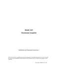
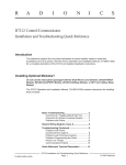
2031
SWITCHER FOLLOWER
Installation and Operating Instructions
The 2031 Switcher Follower can be used with all American Dynamics Matrix Switching Systems employing control codes
from 1650, 2150, a 1995, 1996, 2050, or 1024 Systems. The 2031 Switcher Follower is used to provide simultaneous audio
callup of a camera site when the video from that site is called to a monitor. Other uses include the operation of panel displays
showing called or alarmed camera sites.
The software/firmware furnished with this equipment is confidential to and is copyrighted by SENSORMATIC
ELECTRONICS CORPORATION. It is not to be copied or disclosed in any manner without the express written consent of
SENSORMATIC. The software/firmware is furnished to the purchaser under a license for use on a single system.
Information furnished by SENSORMATIC is believed to be accurate and reliable. However, no responsibility is assumed by
SENSORMATIC for its use; nor for any infringements of other rights of third parties which may result from its use. No
license is granted by implications or otherwise under any patent or patent rights of SENSORMATIC.
Copyright 2000 by Sensormatic. All rights reserved.
AMERICAN
DYNAMICS
The installation of this product should be made by qualified
service personnel and should conform to all local codes.
CAUTION
RISK OF ELECTRIC SHOCK
DO NOT OPEN
The lightning flash with arrowhead
symbol, within an equilateral
triangle, is intended to alert the
user to the presence of uninsulated
"dangerous voltage" within the
product's enclosure that may be of
sufficient magnitude to constitute a
risk of electric shock to persons.
!
CAUTION: TO REDUCE THE RISK OF ELECTRIC SHOCK,
DO NOT REMOVE COVERS (OR BACK) .
NO USER-SERVICEABLE PARTS INSIDE.
REFER SERVICING TO QUALIFIED SERVICE PERSONNEL
WARNING
!
The exclamation point within an
equilateral triangle is intended to
alert the user to the presence of
important operating and maintenance
(servicing) instructions in the
literature accompanying the product.
UNPACKING AND INSPECTION
To reduce the risk of fire or shock hazard, do
not expose this product to rain or moisture.
Unpack carefully. This is an electronic product and should
be handled as such. Compare the items received with the
packing list with your order.
This equipment has been tested and
found to comply with Part 15 of the
FCC Rules.
Be sure to save:
1. The shipping cartons and insert pieces. They are the
safest material in which to make future shipments of
the product.
2. The IMPORTANT SAFEGUARDS sheet.
3. These Installation and Operating Instructions.
Operation is subject to the
following two conditions: 1. This
device may not cause harmful
interference, and 2. This device
must accept any interference
received, including interference
that may cause undesired operation.
)
MAINTENANCE
User maintenance of this unit is limited to external cleaning
and inspection. For specific recommendations refer to the
IMPORTANT SAFEGUARDS sheet packaged with this product.
INSTALLATION AND SERVICE
If you require information during installation of this
product or if service seems necessary, contact the
Sensormatic Repair and Service Department at (800)
442-2225. You must obtain a Return Authorization Number
and shipping instructions before returning any product for
service.
Do not attempt to service this product yourself. Opening or
removing covers may expose you to dangerous voltages or
other hazards. Refer all servicing to qualified personnel.
QA301D
Table of Contents
Description ............................................................ 1
Features ................................................................. 1
Installation............................................................ 2
Mounting......................................................2
Monitor/Camera Select ................................2
DIP Switches................................................2
Connections
Relay Connections ..................................... 4
Data Line Connections............................... 5
Data Line Input ............................................5
Control Code Line Connections................. 5
Operation.............................................................. 6
Power Sources ...................................................... 7
Operating Indicators............................................. 7
Typical System Connections ....................Appendix
Specifications ...........................................back page
DESCRIPTION
SELECT
ON
GROUP 1
DATA LINE
1
2
3
4
5
6
7
8
9
10
11
12
13
14
15
16
A B
A B
A B
A B
A B
A B
A B
A B
A B
A B
A B
A B
A B
A B
A B
A B
19
20
21
22
23
24
25
26
27
28
29
30
31
32
A B
A B
A B
A B
A B
A B
A B
A B
A B
A B
A B
A B
A B
A B
IN
OFF
ABCDEF
PWR
ON
OFF
DATA
GROUP 2
17
18
1
OUT
ABCDEF
ON
OFF
A B
A B
ABCDEF
G1 IN G1 OUT G2 IN G2 OUT
ON
120V
60Hz
OFF
ABCDEF
A B
BWS
A B
A B
A B
Figure 1 - 2031 Switcher Follower
DESCRIPTION
FEATURES
The 2031 Switcher\Follower is used to provide simultaneous
relay closures corresponding to a camera when it is called to a
monitor. Uses incluse the audio callup or operation of panel
displays showing called or alarmed camera sites, etc.
The 2031 Switcher\Follower has the following features:
☛ SCREW TERMINAL WIRE CONNECTORS
☛ LED INDICATOR FOR “VALID" CODE
The 2031 receives data from either a LAN output of a 1995, a
DATA LINE output of a 1996, or the Control Code output of
either a 1600, 1650, or 2150 System. If the 2031 operates via
control code, a dip switch, located on the main printed circit
board, is used to select the Control Code mode.
☛ LED POWER INDICATOR
☛ DIP SWITCH SELECTION FOR CAMERA
GROUPAND MONITOR
The 2031 then filters the incoming codes for either camera
group or Monitor. The unit contains 32 addressable,
normally open relays. The 32 relays can be grouped in
series or, in two alike groups of 16. Each of the two groups
can control 16 relays following one monitor and 16 cameras.
☛ COMPATIBLE WITH EITHER DATA LINE OR
CONTROL CODE
☛ UNIVERSAL MOUNT CABINET
IF YOU ENCOUNTER ANY PROBLEMS
OPERATING THIS UNIT, OR NEED
TECHNICAL ASSISTANCE, CALL OUR
SERVICE CENTER AT:
within the United States: 1-800-442-2225
outside the United States: (845) 624-7600
1
INSTALLATION
INSTALLATION
Monitor/Camera Select
This installation should be made by qualified service
personnel and should conform to all local codes. Safeguards
must be taken to avoid unintentional operation by employees
and maintenance personnel working about the premises, by
falling objects, by customers, by building vibration, and by
similar causes.
The DIP switches are also used in the 2031 to determine
monitor and camera group selections.
The cabinet of a 2031 Switcher Follower may be surface or
rack mounted in any convenient location with adequate
ventilation. For proper ventilation allow at least three feet
(1m) from the rear of the racks to any wall and one EIA rack
height (1 3/4 inches) between units.
Mounting
The 2031 is shipped with mounting ears flush with the front
panel, and can be mounted to the front of a standard 19-inch
rack.
The mounting ears of the 2031 can also be placed such that
they are flush with the rear panel. This allows the 2031 to be
mounted in a rack equipped with mounting channels.
The unit can also be surface mounted. Mount the ears so that
they are either flush with athe top or bottom covers of the
unit, or offset from the covers.
DIP Switches
The four, 8-position DIP switches located on the rear of the
2031 under the label “SELECT”, are used to determine
monitor and camera group selections. The top two DIP
switches (1 & 2) set the parameters of the GROUP 1 relays.
The lower two DIP switches (3 & 4) set the parameters of the
GROUP 2 Relays.
The configuration of the paur of 8-positions DIP switches, (1
& 2 or 3 & 4) determines the monitor to be followed (1-64),
and the camera group to be followed (in groups of 16). All
the switches are programmed in binary. The first and third
switches are programmed to correspond to the desired
monitor. The second and fourth switches are programmed to
correspond to the desired camera block (in groups of 16).
TABLE 1 shows the complete correspondence of DIP switch
settings to the monitor and camera numbers.
Note:
The two groups can be set to two different monitor
and camera numbers, if desired.
Optimally, the 2031 should be located near the Switching
Systems (1995, 1996, 2050, 1024) or near the Control Code
Line of a 1600, 1650, or 2150 Switching System. Avoid heat
sources or poorly ventilated racks.
DIP Switch 1
DIP Switch 2
DIP Switch 3
DIP Switch 4
SELECT
GROUP 1
ON
DATA LINE
1
2
3
4
5
6
7
8
9
10
11
12
13
14
15
16
A B
A B
A B
A B
A B
A B
A B
A B
A B
A B
A B
A B
A B
A B
A B
A B
19
20
21
22
23
24
25
26
27
28
29
30
31
32
A B
A B
A B
A B
A B
A B
A B
A B
A B
A B
A B
A B
A B
A B
IN
OFF
ABCDEF
PWR
ON
OFF
DATA
GROUP 2
17
18
1
OUT
ABCDEF
ON
OFF
A B
A B
ABCDEF
G1 IN G1 OUT G2 IN G2 OUT
ON
OFF
ABCDEF
A B
BWS
Figure 2 - Location of DIP Switches
2
A B
A B
A B
120V
60Hz
CONNECTIONS
A
GROUP 1
PWR
SELECT
ON
2
3
4
5
6
7
8
9
10
11
12
13
A B
A B
A B
A B
A B
A B
A B
A B
A B
A B
A B
A B
A B
20
21
A B
A B
14
15
16
IN
OFF
ABCDEF
ON
OFF
DATA
GROUP 2
DATA LINE
1
17
18
19
22
23
24
25
26
27
28
A B
A B
A B
1
29
30
31
32
A B
A B
A B
A B
OUT
ABCDEF
ON
OFF
A B
A B
A B
A B
A B
A B
A B
A B
A B
A B
ABCDEF
G1 IN G1 OUT G2 IN G2 OUT
ON
120V
60Hz
OFF
ABCDEF
A B
BWS
A B
A B
A B
Figure 3 - 2031 Relay Groups
1
A
B
2
A
B
3
A
G1 IN
B
A
B
G1 OUT
A
B
Figure 4 - 2031 Relay Contacts (Group 1)
CONNECTIONS
are connected to relays 17-32. The Group IN connections are
used for determining the function of the associated relays,
such as providing a user-supplied voltage, a short to ground,
or a unique signal on relay activation. The Group IN pins can
also be used as inputs from cascading 2031 units. The Group
OUT connections are used to connect the associated relays to
a single responding device, such as a speaker or an indicator
light, or for cascading to additional 2031’s.
Relay Connections
The 2031 Switcher Follower provides relay closures only;
they are not intended to supply power. Two groups (GROUP
1 and GROUP 2) of four 12-pin relay connectors are
provided on the rear panel (see Figure 3). Each group
provides connections for double pole relays. The two groups
provide 32 pairs of relay closures. Figure 4 illustrates the
internal 2031 relay interconnections for Group 1 relays.
For ease of attaching to external equipment, each connector is
supplied with a mating screw terminal connector, shown in
Figure 5. Insert the signal and shield wires into the slots of
the mating connector and tighten the hold-down screws.
When all lines have been connected, insert the 12-pin
connectors into the rear panel mating terminals.
The relay connections to the unit must be made with shielded,
2-wire twisted pair (22 AWG or heavier gauge wire or
equivalent). The shield wire is to be connected to the
grounding terminal.
The relay contact ratings are 0.6 Amps at 24 VAC, or 2 Amps
at 30 VDC, resistive load. Power through the relays is not
supplied by the 2031.
Each set of three pin connections is labeled with a relay
number, from 1 through 32, corresponding to one of the
monitors of the monitor group(s) selected. Each pin within
one of the numbered sets is also labeled, under the connector,
with an A, a B, and a ground symbol. The A and B pins on
each connection are the contacts for one side of each double
pole relay. The contacts for the other side of each relay are
connected to the common Group connectors (next paragraph).
The ground pin is provided for shielding.
HOLD DOWN SCREWS
A
B
A
One 12-pin connector on the lower right of the 2031 rear
panel contains the common connections for each relay group.
Each set of pins is labeled with the group number G1 IN, G1
OUT, G2 IN, and G2 OUT, and each pin is labeled with an A,
B, and ground. The A and B pins are common contacts for
the other side of the double pole relays; G1 IN and OUT are
connected to relays 1-16 (see Figure 4), and G2 IN and OUT
B
A
B
A B
OR
CT
E
N
ON
N
TC
IO
R
CT
E
E
S
R
N
I
DI
IS
TH
Figure 5 - Typical 12-Pin Connector
4
CONNECTIONS
Data Line Connections
Control Code Line Connections
A DATA LINE is connected from the DATA LINE OUT
BNC on a Matrix Bay to the DATA LINE IN BNC on the
rear panel of the Switcher Follower (Older 1995 systems used
the term LAN IN/OUT). Use a good grade RG-59 video
cable (Belden 8241 or equivalent). The DATA LINE OUT
BNC on the Switcher Follower must be fitted with a 75-ohm
BNC terminator, or if used to loop to other DATA LINE
controlled equipment, it must be terminated at the end of the
run.
The 12-pin terminal connector located at the lower left side of
the rear panel is used for Control Code connections. The
connector is labeled B, W, and S. The B is for the BLACK
code wire, the W is for the WHITE code wire, and the S is for
the SHIELD wire.
CAUTION - Due to the presence of noninsulated components with hazardous voltages,
the following internal adjustments should be
performed by qualified service personnel only.
The LED labeled DATA LINE on 2031 will illuminate when
valid code is received on the Data Line.
DATA LINE Input
If the 2031 Switcher Follower is used with Control Code,
remove the top cover of the unit and locate the DIP switch on
the printed circuit board (see Figure 6, below). Set the eighth
switch position of this DIP switch to the ON position. This
setting enables the use of Control Code in the 2031.
After completing the Data Line connections, plug in the
power cord. When the 2031 receives a valid code through the
Data Line inputs, the green Data Line LED illuminates. The
illumination of the Data Line LED is confirmation that the
relays associated with a particular monitor or camera are
opening and closing as each particular monitor or camera is
called.
Note: As shipped, the 2031 is set to operate in the Data Line
mode; this switch is set to the OFF position.
Control Code lines must be terminated in 120 ohms. Check
the last unit on each line to ensure that 120-ohm termination
is present. Intermediate units on a Control Code line must
not have 120-ohm termination. To remove the termination of
the 2031 code line, jumper J32 must be removed from the
main PCB. See Figure 6 for the location of this jumper.
If the DATA LINE LED does not illuminate, check for
proper operation of the 1995. 1996, or 1024 CPU. Check all
your connections. If all the connections are as they should be
and the 2031 still does not operate properly, unplug the 2031
and remove the top cover. Check the DIP switch on the main
printed circuit board. All switches should be in the OFF
position. Refer to the illustration at right.
Note: As shipped, the 2031 is set for 120-ohm termination;
this jumper is inserted.
120 ohm Termination Jumper
J32
ON
OFF
12345678
Dip Switch
Power Cord
Figure 6 - DIP Swich Location on PCB
5
CONNECTIONS AND OPERATION
Control Code Line Connections
In switching systems using Contol Code, the Switcher Follower
must be connected to the code line that contains the cameras
and monitor to be followed. Each code line contains data for
64 cameras and eight monitors for 1650 systems, and a
maiximum of 32 cameras and five monitors for 2150 systems.
The Control Code line connections to the Switcher Follower
must be shielded, 2-wire twisted pair (Belden 8760; for
plenum use Belden 88760 or equivalent).
2032
2031
2032
2031
2032
2031
B W S
B W S
B W S
T
OTHER CODE
LINES
CODE
DISTRIBUTOR
Code Lines are NEC Class 2, low voltage circuits. Where
local codes permit, installation in conduit is not required.
Avoid installation near high voltage or other potential
interference sources.
T = 120 OHM TERMINATION
Figure 8 - Code "Daisy Chain" Configuration
OPERATION
Multiple 2031s can be connected in a “Star” configuration to
a Control Code distribution unit (1691 or 2091). See Figure 7.
For this connections, each 2031 must have a 120 ohm
termination.
After completing the Control Input connections, plug in the
power cord. When the 2031 receives a valid code through the
Control Line input, the green Data Line LED illuminates. The
illumination of the Data Line LED is confirmation that the
relays associated with a particular monitor or camera are
opening and closing as each particular monitor or camera is
called.
A maximum of three Control Code devices can be “DaisyChained” on a single code line. When devices are daisychained, do not terminate the control line with intermediate
devices. In addition, make sure the intermediate equipment
does not contain a 120 ohm terminating resistor. If it does,
remove it (see page 5). See Figure 8 for a daisy-chained
configuration.
2031
2032
B W S
T
22031
032
B W S
T
For 1650A operation, there can be a maximum of four control
lines. The first control line is for monitors 1-8 and cameras 164. The second control line is for monitors 1-8 and cameras
65-128. The third control line is for monitors 9-16 and
cameras 1-64. The fourth control line is for monitors 9-16 and
cameras 65-128.
22031
032
B W S
When setting the DIP switches, enter the actual monitor and
camera group (i.e., monitor 12, cameras 1-64, GROUP 1;
contacts for cameras 1-16).
T
If the DATA LINE LED does not illuminate, check for
proper operation of the 1995. 1996, or 1024 CPU. Check all
your connections. If all the connections are as they should be
and the 2031 still does not operate properly, unplug the 2031
and remove the top cover. Check the DIP switch on the main
printed circuit board. All switches should be in the OFF
position. Refer to the illustration on page 5 for this DIP
switch location.
OTHER CODE
LINES
CODE
DISTRIBUTOR
T = 120 OHM TERMINATION
Figure 7 - Code "Star" Configuration"
If the green code LED is flickering, the code lines may be
backwards. Try reversing the black and white code lines.
In operation with 1650A, 1995, 1996, and 1024 systems, the
2031 senses jumps between groups of 64 cameras. When
going from one group to another, the 2031 will place one
group in the OFF state (open all relays) when going to the
next group of 64 cameras.
Figure 4 - DIP Switch Location on PCB
6
POWER SOURCES
Power Sources
DO NOT CONNECT THE EQUIPMENT TO A POWER
SOURCE UNTIL READY TO “POWER UP”. Make all
connections to the 2031 data line, or code input and relay
connections and set the DIP switches prior to power up.
The 2031 Switcher\Follower does not contain an On/Off
Switch. The socket outlet shall be located near the equipment
and shall be readily accessible. The 120V units are supplied
with a pendant 3-wire cord and plug for mating to the primary
source outlet. The 230V units are supplied with a Euro style
IEC 320 type inlet. A suitable detachable cord should be
connected between the IEC 320 inlet and the power source.
The cord should conform to all national and local use code
requirements.
Switcher\Followers are available in two models, depending
on the power source to be used:
AD2031: 120 V, 50/60Hz
AD2031-1: 230 V, 50/60Hz
Operating Indicators
A green POWER LED power indicator located on the rear
panel illuminates when power is applied.
When the unit is receiving valid code, the green DATA LINE
LED on the rear panel will illuminate and glow steadily. If it
flickers, there may be a problem with the Control Input line.
7
APPENDIX
2031 SWITCHER FOLLOWER
CHANNEL B
CAMERA # 1
CHANNEL A
1
2
3
A B
A B
A B
4
A B
DATALINE/LAN
FROM CPU
SELECTS MONITOR # AND
CAMERA GROUP # TO FOLLOW
SELECT
GROUP 1
PWR
DATA
GROUP 2
ON
5
ABCDEF
6
9
7
10
8
13 11
14
12
ABCDEF
A B
A B
A B
18
A B
A B
2119
A B
A B
22 20
A B
A B
25
23
A B
A B
26
24
A B
A B
29 27
A B
30
A B
28
1
31
OUT
32
ABCDEF
A B
OFF
ON
A B
17
OFF
ON
16
IN
OFF
ON
DATA LINE
15
A B
A B
A B
A B
A B
A B
A B
A B
A B
A B
A B
A B
A B
A B
A B
G1 IN G1 OUT G2 IN G2 OUT
ABCDEF
OFF
A B
BWS
A B
A B
A B
CONTROL CODE INPUT
G1 IN G1 OUT G2 IN G2 OUT
High Speed DATA OUT to
Additional 2031s or Bays
A B
A B
A B
A B
CHANNEL B
CHANNEL A
TYPICAL SYSTEM CONNECTIONS
2031 SWITCHER FOLLOWER
RELAY
ALARMS
-CODE-
CAMERAS
1
3
5
7
9
11
13
15
17
19
21
23
25
27
29
31
2
4
6
8
10
12
14
16
18
20
22
24
26
28
30
32
MONITORS
1
2
1
3
4
2
5
KEYBOARDS
3
2
3
4
5
RS232 PORTS
2150
BWS
RS-232
1
MONITOR
MONITOR
MONITOR
MONITOR
8
6
4
2
7
5
3
1
2
3
4
A
A
A
A
A
A
A
A
B
B
B
B
B
B
B
B
O
U
T
O
U
T
O
U
T
O
U
T
O
U
T
O
U
T
O
U
T
O
U
T
J1
OUT
B
W
S
1650
1650A
from 1600, 1650A, or 2150 Systems
BWS
SELECT
GROUP 1
PWR
DATA
GROUP 2
ON
5
ABCDEF
6
9
7
10
8
13 11
14
12
ABCDEF
A B
A B
A B
18
A B
A B
2119
A B
A B
22 20
A B
A B
25
23
A B
A B
26
24
A B
A B
29 27
A B
30
A B
28
1
31
OUT
32
ABCDEF
A B
OFF
ON
A B
17
OFF
ON
16
IN
OFF
ON
DATA LINE
15
A B
A B
A B
A B
A B
A B
A B
A B
A B
A B
A B
A B
A B
A B
A B
G1 IN G1 OUT G2 IN G2 OUT
ABCDEF
OFF
BWS
A B
A B
A B
A B
2031
DATALINE OUT to
additional 2031's or 75-ohm
terminator
DECLARATION OF CONFORMITY
According to ISO/IEC Guide 22 and EN45014
Manufacturer’s Name:
Sensormatic Electronics Corporation
Manufacturer’s Address:
1 Blue Hill Plaza
2nd Floor
Pearl River, New York, 10965 USA
Declares, that the product listed below:
Name/Type:
Switcher / Follower
Model Number:
AD2031-1
complies with all applicable directives as demonstrated by conformance to the following Product Specifications:
Safety:
EN 60950: 1992
EMC:
EN 50130-4: 1995
EN 55022: 1994 , Class B
EN 61000-3-2: 1995
EN 61000-3-3: 1995
EN 61000-4-2: 1995
EN 61000-4-3: 1996
EN 61000-4-4: 1995
EN 61000-4-5: 1995
EN 61000-4-6: 1996
EN 61000-4-11: 1994
Supplementary Information:
The products herewith comply with the requirements of the Low Voltage Directive, 73/23/EEC as amended by
93/68/EEC, and the EMC Directive, 89/339/EEC as amended by 93/68/EEC.
Pearl River, NY, USA
15 December, 2000
Harold D. Johnson, Ph.D.
Director of Engineering
European Contact: Sensormatic France S.A.
7, rue Alexis de Tocqueville, Parc de Haute Technologie, 92183 ANTONY CEDEX
SPECIFICATIONS
Electrical Ratings:
AD2031
AD2031-1
120 VAC, 50/60Hz, 15 W
230 VAC, 50/60Hz, 125 mA
Relay Contact Ratings: 0.6 A at 24 VAC, 2.0A at 30 VDC
Mounting:
Free Standing or Rack Mount
Weight:
7 lbs (1.4 kg)
Dimensions:
3.5” H x 17” W x 8” D (89 x 432 x 203 mm)
Sensormatic Video Systems Divsion
One Blue Hill Plaza
Pearl River, New York 10965
(845) 624-7600
Technical Support Center: 800-442-2225
FAX: (845) 624-7685
8000-1823-01, Revision A
December, 2000
Printed in USA