1
samos®PRO
Gateways
Operating instructions
Doc. No. BA000587
Issued: 09/2009 (Rev. A)
© 2009 Wieland Electric GmbH
This document is protected by the law of copyright, whereby all rights established therein
remain with the company Wieland Electric GmbH. Reproduction of this document or parts
of this document is only permissible within the limits of the legal determination of Copyright Law. Alteration or abridgement of the document is not permitted without the explicit
written approval of the company Wieland Electric GmbH.
Microsoft, Windows 98, Windows ME, Windows 2000, Windows XP and .NET. Framework are registered trademarks of Microsoft Corporation. Other product names and
trademarks mentioned in these operating instructions are trademarks or registered trademarks of the respective owners.
Wieland Electric | BA000587 | 09/2009 (Rev. A)
3
Contents
Contents
4
1
1.1
1.2
1.3
1.4
1.5
1.6
1.7
1.8
About this document........................................................................................ 6
Function of this document .......................................................................................... 6
The samos®PRO operating instructions...................................................................... 6
Target group ................................................................................................................ 6
Information depth........................................................................................................ 7
Scope........................................................................................................................... 7
Abbreviations used...................................................................................................... 7
Symbols used .............................................................................................................. 7
Trademarks .................................................................................................................. 8
2
2.1
2.2
2.3
2.3.1
2.3.2
On safety .......................................................................................................... 9
Qualified safety personnel ........................................................................................... 9
Correct use .................................................................................................................. 9
Environmental protection .......................................................................................... 10
Disposal ..................................................................................................................... 10
Separation of materials.............................................................................................. 10
3
3.1
3.2
3.2.1
3.2.2
3.2.3
3.2.4
3.2.5
3.3
Product description samos®PRO gateways .................................................... 11
Device variants .......................................................................................................... 11
Data transmitted into the network (network input data sets) ................................... 12
Logic results .............................................................................................................. 14
Module input and output values ............................................................................... 14
Routing of data from a second network ................................................................... 14
Configuration checksums (CRCs).............................................................................. 14
Error and status information of the modules ............................................................ 14
Data received from the network (network output data sets) .................................... 17
4
4.1
4.1.1
4.1.2
4.2
4.3
4.3.1
4.3.2
4.3.3
4.3.4
4.3.5
Mounting and basic configuration of the gateways ....................................... 18
Mounting/Dismantling............................................................................................... 18
Steps for mounting the modules............................................................................... 18
Steps for dismantling the modules ........................................................................... 20
Electrical installation.................................................................................................. 21
First configuration steps............................................................................................ 21
Establishing a connection between gateway and PC ............................................... 21
Configuration of the gateways .................................................................................. 22
Transfer of a configuration ........................................................................................ 23
Verification of a configuration ................................................................................... 23
Upload of a configuration.......................................................................................... 24
5
5.1
5.1.1
5.1.2
5.1.3
5.2
5.2.1
5.2.2
5.2.3
5.2.4
5.2.5
5.2.6
Ethernet gateways.......................................................................................... 25
Common features of the Ethernet gateways ............................................................ 25
TCP/IP configuration interface................................................................................... 25
Ethernet TCP/IP socket interface............................................................................... 28
TCP/IP process image example ................................................................................. 35
EtherNet/IP gateway.................................................................................................. 37
Interfaces and operation............................................................................................ 37
Basic configuration — assigning a device name and IP address.............................. 38
Configuration of the interface to the PLC — how the data are transferred .............. 39
TCP/IP configuration interface................................................................................... 48
Ethernet TCP/IP socket interface............................................................................... 48
Diagnostics and troubleshooting............................................................................... 48
Wieland | BA000587 | 09/2009 (Rev. A)
Contents
5.3
5.3.1
5.3.2
5.3.3
5.3.4
5.3.5
5.3.6
5.4
5.4.1
5.4.2
5.4.3
5.4.4
5.4.5
5.4.6
5.4.7
Modbus TCP gateway................................................................................................50
Interfaces and operation ............................................................................................50
Basic configuration — assigning an IP address.........................................................51
Configuration of the Modbus TCP interface to the PLC — how the data is
transferred..................................................................................................................51
TCP/IP configuration interface ...................................................................................57
Ethernet TCP/IP socket interface ...............................................................................57
Diagnostics and troubleshooting ...............................................................................57
PROFINET IO gateway ...............................................................................................59
Interfaces and operation ............................................................................................59
Basic configuration – assigning a device name and IP address ................................60
PROFINET configuration of the gateway – how the data is transferred....................61
PROFINET configuration of the gateway — which data are transferred ...................63
TCP/IP configuration interface ...................................................................................69
Ethernet TCP/IP socket interface ...............................................................................69
Diagnostics and troubleshooting ...............................................................................69
6
6.1
6.1.1
6.1.2
6.1.3
6.1.4
Fieldbus gateways.......................................................................................... 71
PROFIBUS DP gateway..............................................................................................71
Interfaces and operation ............................................................................................71
Planning .....................................................................................................................74
PROFIBUS configuration of the gateway – how the data is transferred ...................76
Diagnostics and troubleshooting ...............................................................................81
7
7.1
7.2
7.3
7.3.1
7.3.2
7.3.3
7.3.4
7.3.5
7.3.6
7.3.7
7.4
Layout and content of the process image ...................................................... 83
Routing.......................................................................................................................83
Default settings for the operational data ...................................................................83
Customizing the operational data (samos®PRO to Network) ....................................84
The toolbar .................................................................................................................85
Available data area .....................................................................................................85
Gateway Data area .....................................................................................................86
Tag names area ..........................................................................................................87
Tag names for incoming data (Network to samos®PRO) ..........................................87
Saving and loading a configuration ...........................................................................88
Importing and exporting a configuration ...................................................................88
Monitoring the operational data online......................................................................88
8
8.1
8.1.1
8.1.2
8.2
8.3
8.4
8.5
8.6
Technical specifications ................................................................................. 90
Technical specifications gateways.............................................................................90
PROFIBUS DP ............................................................................................................90
EtherNet/IP, PROFINET IO, Modbus TCP...................................................................90
Technical specifications, supply circuit .....................................................................91
General technical specifications ................................................................................91
Dimensional drawings ...............................................................................................92
Ordering information samos®PRO gateways ............................................................93
Ordering information accessories/spare parts ...........................................................93
9
9.1
9.2
Annex ............................................................................................................. 94
Index of tables............................................................................................................94
Index of illustrations...................................................................................................95
Wieland Electric | BA000587 | 09/2009 (Rev. A)
5
About this document
1
About this document
Please read this chapter carefully before working with these operating instructions and the
samos®PRO gateways.
1.1
Function of this document
These operating instructions only apply in conjunction with the other samos®PRO operating
instructions (see section 1.2 “The samos®PRO operating instructions” below) and provide
the technical personnel at the machine manufacturer or machine operating organisation
information on safe mounting, adjustment, electrical installation, commissioning as well as
on operation and maintenance of the samos®PRO gateways.
These operating instructions do not provide information on the operation of the machine in
which a samos®PRO modular safety controller and a samos®PRO gateway is integrated.
Information on this is to be found in the appropriate operating instructions for the machine.
1.2
The samos®PRO operating instructions
For the samos®PRO system there are three operating instructions with clearly distinguished
fields of application as well as mounting instructions for each module.
• The mounting instructions (Wieland document nos. BA000572, BA000583) are enclosed
with each samos®PRO module. They inform on the basic technical specifications of the
modules and contain simple mounting instructions. Use the mounting instructions when
mounting samos®PRO safety controllers.
• The samos®PRO hardware operating instructions (Wieland document no. BA000497)
describe all samos®PRO modules and their functions in detail. Use the Hardware operating instructions in particular to configure samos®PRO safety controllers.
• The samos®PRO gateways operating instructions (this document) describe all samos®PRO
gateways and their functions in detail.
• The samos®PLAN operating instructions (Wieland part no. BA000518) describe the software-supported configuration and parameterization of the samos®PRO safety controllers.
In addition, the software operating instructions contain the description of the diagnostics
functions that are important for operation and detailed information for the identification
and elimination of errors. Use the Software operating instructions in particular for the
configuration, commissioning and operation of samos®PRO safety controllers.
1.3
Target group
These operating instructions are addressed to planning engineers, machine designers and
the operators of systems in which a samos®PRO modular safety controller is integrated and
who want to exchange data with a fieldbus (a controller) via a gateway.
They are also addressed to people who are placing a samos®PRO gateway in operation for
the first time or maintaining it.
6
Wieland | BA000587 | 09/2009 (Rev. A)
About this document
1.4
Information depth
These operating instructions contain information on the samos®PRO gateways on the following subjects:
•
•
•
•
•
•
mounting
implementation into a network
configuration via samos®PLAN software
data transfer to and from the network
status information, planning and related mapping
part numbers
Warning!
Pay attention to the safety notes and safety measures on the samos®PRO gateway!
WA RNING
We also refer you to our homepage on the Internet at
www.wieland-electric.com ("Support/Download Center")
Note
There you will find the following files for download:
• SP-EN-IP EDS file for EtherNet/IP
• SP-EN-PN GSDML file for Profinet IO
• SP-PROFIBUS-DP GSD file for PROFIBUS DP
1.5
Scope
These operating instructions apply to the samos®PRO gateway modules SP-PROFIBUS-DP,
SP-EN-MOD, SP-EN-IP and SP-EN-PN with the following entry in the Operating Instructions field of the type label: BA000587.
This document is part of Wieland document number BA000587 (“samos®PRO gateways”
operating instructions in all available languages).
This document is the original operating instructions.
1.6
Abbreviations used
Enhanced Function Interface
EFI
Short integer = 1 Byte
SINT
Unsigned double integer = 4 Bytes = 2 Words
UDINT
Unsigned integer = 2 Byte = 1 Word
UINT
1.7
Symbols used
Refer to notes for special features of the device.
Wieland Electric | BA000587 | 09/2009 (Rev. A)
Notes
7
About this document
Warning!
A warning notice indicates an actual or potential risk or health hazard. They are designed
to help you to prevent accidents.
Read carefully and follow the warning notices!
WA RNING
1.8
Trademarks
Windows 98, Windows NT 4.0, Windows 2000, Windows XP and Internet Explorer are
registered trademarks of Microsoft Corporation in the USA and other countries.
SIEMENS SIMATIC Manager is a registered trademark of SIEMENS AG.
DeviceNet and DeviceNet Safety are registered trademarks of the Open DeviceNet Vendor
Association, Inc. (ODVA).
Other product names and company names referenced in this manual are trademarks or
registered trademarks of their respective companies.
8
Wieland | BA000587 | 09/2009 (Rev. A)
On safety
2
On safety
This chapter deals with your own safety and the safety of the equipment operators.
Please read this chapter carefully before working with a samos®PRO gateway.
2.1
Qualified safety personnel
The samos®PRO gateway must only be installed, commissioned and serviced by qualified
safety personnel.
Qualified safety personnel are defined as persons who …
• have undergone the appropriate technical training
and
• have been instructed by the responsible machine operator in the operation of the machine and the current valid safety guidelines
and
• have access to the operating instructions of the samos®PRO gateway and samos®PRO
modular safety controller and have read and familiarised themselves with them.
2.2
Correct use
The samos®PRO gateways can only be operated with a samos®PRO system. The firmware
version of the connected SP-SCON must be at least V1.10.0, the version of the
samos®PLAN configuration software must be at least 1.2.0.40.
The samos®PRO gateways do not have a dedicated voltage supply.
The samos®PRO gateways are not suitable for operation on a safety fieldbus!
These gateways only generate non-safety-related fieldbus data (status bytes) for control
and diagnostics purposes.
Do not use non-safe data from a samos®PRO gateway for safety related applications!
With the samos®PRO gateways it is possible to integrate non-safe data into the logic editor
such that the safety function of the samos®PRO system is compromised. Never implement
the gateway into a samos®PRO system without having this danger checked by a safety
specialist.
WA RNING
These modules may only be used by qualified safety personnel and only on the machine
where they have been installed and initialised by qualified safety personnel in accordance
with the operating instructions.
Pay attention to the safety notes and safety measures on the samos®PRO gateway!
If the device is used for any other purposes or modified in any way — also during mounting and installation — any warranty claim against Wieland Electric GmbH shall become
void.
WA RNING
Wieland Electric | BA000587 | 09/2009 (Rev. A)
9
On safety
• During the mounting, installation and usage of the samos®PRO gateway, observe the
Notes
standards and directives applicable in your country.
• The national/international rules and regulations apply to the installation, commissioning,
use and periodic technical inspection of the samos®PRO modular safety controller, in particular:
− EMC directive 2004/108/EC,
− Provision and Use of Work Equipment Directive 89/655/EC,
− the work safety regulations/safety rules.
• The operating instructions must be made available to the operator of the machine where
a samos®PRO system is used. The machine operator is to be instructed in the use of the
device by qualified safety personnel and must be instructed to read the operating instructions.
The samos®PRO system complies, as per the “radiated emissions” generic standard, with
the requirements of class A (industrial applications). The samos®PRO system is therefore
only suitable for use in an industrial environment.
WA RNING
2.3
Environmental protection
The samos®PRO gateways are designed for minimum impact on the environment, they consume only a minimum of energy and resources.
At work, always act in an environmentally responsible manner.
2.3.1
Disposal
Unusable or irreparable devices should always be disposed as per the applicable national
regulations on waste disposal (e.g. European waste code 16 02 14).
Note
We would be pleased to be of assistance to you on the disposal of these devices. Contact us.
2.3.2
Separation of materials
Only appropriately trained personnel are allowed to separate materials!
Caution is required when dismantling devices. There is a risk of injuries.
WA RNING
Before you send the devices for appropriate recycling, it is necessary to separate the different materials of the samos®PRO gateways.
Separate the housing from the rest of the parts (in particular the circuit board).
Send the separated parts for recycling as appropriate (see Tab. 1).
Tab. 1: Overview on
disposal by components
Components
Disposal
Product
Housing, circuit boards, cables, connectors Electronic recycling
and electrical connecting pieces
Packaging
Cardboard, paper
Paper/cardboard recycling
10
Wieland | BA000587 | 09/2009 (Rev. A)
Product description samos®PRO gateways
3
Product description samos®PRO
gateways
The samos®PRO gateways allow the samos®PRO System to send and receive non-safety
related data to and from the external fieldbus system for control and diagnostics purposes.
In this manual, the data exchanged between the samos®PRO system and the respective
network will be considered always from the network master (PLC) point of view. Therefore
data sent from the samos®PRO system into the network will be referred to as input data
while data received from the network will be referred to as output data.
Note
Do not operate a samos®PRO gateway on a safety fieldbus!
The samos®PRO gateway modules are not suitable for operation on a safety fieldbus. They
do not support any safety mechanism, which would be mandatory to communicate within
a safety network.
Configuration of the samos®PRO gateways is performed using the samos®PLAN configuration software on a PC or laptop connected to the SP-SCON over RS-232 interface or connected to the Ethernet gateways over Ethernet TCP/IP.
WA RNING
The safety relevant logic of the samos®PRO system operates independently from the gateway. If however the samos®PRO system has been configured to integrate non-safe information from the fieldbus into the logic editor, a decoupling of the gateway can result in availablity problems.
A samos®PRO gateway can only be operated on a samos®PRO system. It does not have a
dedicated voltage supply. It is possible to use two samos®PRO gateways per system.
The gateways are fitted in a 22.5 mm wide housing for 35 mm rails in accordance with
EN 60715.
Ordering information can be found in section 8.5 “Ordering information samos®PRO gateways” on page 93. A list of available accessories can be found in section 8.6 “Ordering
information accessories/spare parts” on page 93.
3.1
Device variants
Four samos®PRO gateways are available for the different network types. Suitable for
Ethernet networks are the EtherNet/IP gateway SP-EN-IP, the Modbus TCP gateway SPEN-MOD and the Profinet IO gateway SP-EN-PN. The PROFIBUS DP gateway SPPROFIBUS-DP is a fieldbus gateway without Ethernet functionality. With the SP-DeviceNet
for DeviceNet and the SP-CANopen for CANopen, two further fieldbus gateways will be
available in the future.
Wieland Electric | BA000587 | 09/2009 (Rev. A)
11
Product description samos®PRO gateways
Tab. 2: Device variants
and features overview
Network type
Ethernet TCP/IP
socket interface
TCP/IP configuration interface
3.2
SP-EN-IP
EtherNet/IP
explicit messaging
Client/server
SP-EN-MOD
Modbus TCP
master & slave
receive method
Client/server
SP-EN-PN
Profinet IO
slave conformance class A
Client/server
SP-PROFIBUS-DP
PROFIBUS DP
slave
Available at
port 9000
Available at
port 9000
Available at
port 9000
–
–
Data transmitted into the network (network input data
sets)
Available data
The samos®PRO gateways can provide the following data:
• Operational data
− Logic results from the samos®PRO main unit (SP-SCON) (see section 3.2.1 on page 14)
− Input values (HIGH/LOW) for all samos®PRO input extension modules in the system
and EFI devices connected (see section 3.2.2 on page 14)
− Output values (HIGH/LOW) for all samos®PRO input/output extension modules
connected (see section 3.2.2 on page 14)
− Output data from another network, i.e. data received by a second gateway in the
samos®PRO system (see section 3.2.3 on page 14)
• Diagnostics
− Checksums (CRCs) (see section 3.2.4 on page 14)
− Error and status information for all modules except the SA-OR-S2 and SA-OR-S1
(see section 3.2.5 on page 14)
Data sets
The physical samos®PRO modules are not represented as typical hardware modules in the
network. Instead, the data available from the samos®PRO system has been organized into
four input data sets.
• Data set 1 (max. 50 bytes) contains the operational data. It can be compiled using the
samos®PLAN tool. Upon delivery there is a default selection for the content of data set 1
which can be freely modified. For details see Tab. 4 on page 13.
For the SP-EN-PN and the SP-PROFIBUS-DP, data set 1 has been subdivided in five input
data blocks, where data block 1-4 contain 12 bytes each and data block 5 contains two
bytes. For detailed information see the section on the related gateway.
• Data set 2 (32 bytes) contains the system configuration CRCs. See Tab. 4 on page 13.
• Data set 3 (60 bytes) contains the individual module status and diagnostics data with
four (4) bytes per module. For details see Tab. 5 on page 15.
• Data set 4 (60 bytes) is currently filled with reserved values.
Tab. 3 gives an overview which data sets are available for which gateway.
12
Wieland | BA000587 | 09/2009 (Rev. A)
Product description samos®PRO gateways
SP-EN-IP
SP-EN-MOD
SP-EN-PN
SP-PROFIBUS-DP
Data set 1
EtherNet/IP or
TCP/IP
Modbus TCP or
TCP/IP
Profinet IO or
TCP/IP
PROFIBUS DP
Data set 2
EtherNet/IP or
TCP/IP
Modbus TCP or
TCP/IP
Profinet IO or
TCP/IP
–
Data set 3
EtherNet/IP or
TCP/IP
Modbus TCP or
TCP/IP
Profinet IO or
TCP/IP
–1)
Data set 4
EtherNet/IP or
TCP/IP
Modbus TCP or
TCP/IP
Profinet IO or
TCP/IP
–
Data set 1
Data set 2
Data set 3
Byte 0
Logic result 1
Overall CRC
Byte 1
Logic result 2
Module status module 0.
Module 0 is always the CPU.
For detailed information about the
module status see Tab. 5.
System CRC
(SCID)
Module status module 1
Reserved
Module status module 2
Byte 2
Logic result 3
Byte 3
Logic result 4
Byte 4
Input values module 1
Byte 5
Input values module 2
Byte 6
Input values module 3
Byte 7
Input values module 4
Byte 8
Input values module 5
Byte 9
Input values module 6
Byte 10
Input values module 7
Byte 11
Input values module 8
Byte 12
Input values module 9
Byte 13
Input values module 10
Byte 14
Input values module 11
Byte 15
Input values module 12
Byte 16
Output values module 1
Byte 17
Output values module 2
Byte 18
Output values module 3
Byte 19
Output values module 4
Byte 20
Output values module 5
Byte 21
Output values module 6
Byte 22
Output values module 7
Byte 23
Output values module 8
Byte 24
Output values module 9
Byte 25
Output values module 10
Byte 26
Output values module 11
Byte 27
Output values module 12
Byte 28
Not assigned
Byte 29
Not assigned
Byte 30
Not assigned
Byte 31
Not assigned
Byte …
Not assigned
Byte 49
Not assigned
Tab. 3: Availability of data
set 1-4
Tab. 4: Overview input
data sets 1-3 (default
settings for EtherNet IP,
Modbus TCP and TCP/IP)
Module status module 3
Module status module 4
Module status module 5
Module status module 6
Module status module 7
…
…
Byte …
…
Byte 56
Module status module 14.
Module 13 and 14 are always the
gateways.
Byte 57
Byte 58
Byte 59
Length
1)
50 bytes
32 bytes
60 bytes
With the SP-PROFIBUS-DP, diagnostics data is available via PROFIBUS standard DP-V0 diagnostics. For more
information on how to retrieve module status and diagnostics data via the PROFIBUS DP gateway please refer to
chapter 6.1 “PROFIBUS DP gateway” on page 71.
Wieland Electric | BA000587 | 09/2009 (Rev. A)
13
Product description samos®PRO gateways
Note
If there are dual channel input or output elements configured at the IO module, then only
the lowest bit represents the element’s input or output status (on/off). It is represented by
the element’s tag name. The highest bit is not supported.
3.2.1
Logic results
Logic results generated by the logic editor of the samos®PRO main unit can be made available to the network. Up to 20 bytes are available where each bit represents one logic result
from the logic editor.
Data set 1 containing the logic results can be customized. For detailed information see the
chapter on the related gateway and chapter 7 “Layout and content of the process image”
on page 83.
3.2.2
Module input and output values
The samos®PRO gateways can transmit all input and output states of all samos®PRO modules connected to the samos®PRO system into the network. Data set 1 containing the input
and output values can be customized. For detailed information see the chapter on the
related gateway and chapter 7 “Layout and content of the process image” on page 83.
Module input and output states
The input and output states of the modules are transmitted using one byte for each module’s inputs and one byte for each module’s outputs where each bit represents the state of
one input or output (on/off).
3.2.3
Routing of data from a second network
If your samos®PRO system contains two gateways, it is possible to rout information received by the first gateway from one network (e.g. from a Modbus PLC) into a second
network via the second gateway (e.g. to a PROFIBUS master) and vice versa.
3.2.4
Configuration checksums (CRCs)
Data set 2 contains the following configuration CRCs for the samos®PRO system:
• Overall CRC (same as system CRC)
• System CRC (SCID)
Each checksum is four bytes long. The overall CRC is the checksum displayed in the
samos®PLAN report. Data set 2 can not be customized.
3.2.5
Error and status information of the modules
Data set 3 contains the module status information transferred to the network.
Four bytes are used for each module (e.g. SP-SDIO). These four bytes are being transferred
in Big Endian format, i.e. in 16 bit word format with the first byte placed in the least significant, or rightmost byte of the integer and the second byte placed in the most significant, or leftmost byte of the integer:
Data set 3 can not be customised.
14
Wieland | BA000587 | 09/2009 (Rev. A)
Product description samos®PRO gateways
Byte
Bit
I/O modules
(e.g. SP-SDIO, SP-SDI)2)
CPU modules
(e.g. SP-SCON)
Gateway modules
0
0
Module operating state
1 = Executing
0 = Any other state
Module operating state
1 = Executing
0 = Any other state
Module operating state
1 = Executing
0 = Any other state
1
Internal error: Internal tests
failed or watchdog test
failed or bad process data or
self test failure
1 = No error
0 = Error
Module operating state is
Critical Fault
1 = No error
0 = Critical Fault
Internal error: Internal tests
failed, bad process data
1 = No error
0 = Error
2
External error: Input test or Power supply out of range
dual channel evaluation
1 = No error
failure, or bad output power 0 = Error
supply range, or output(s)
stuck-at-high or stuck-atlow.
1 = No error
0 = Error
External error: network
connection inactive/failure
1= No error
0 = Error/inactive
3
Reserved
Reserved
Reserved
4
Configuration status
changed to invalid.
1 = Configuration valid
0 = Conf. invalid or unknown
Configuration status
changed to invalid.
1 = Configuration valid
0 = Conf. invalid or unknown
Configuration status
changed to invalid.
1 = Configuration valid
0 = Conf. invalid or unknown
5
Output power supply out of
range.
1 = Power supply o.k.
0 = Power supply out of
range
Output power supply out of
range.
1 = Power supply o.k.
0 = Power supply out of
range
Input status
1 = Valid network communication
0 = Invalid or no communication
6
Reserved
EFI 1 communication failure Output status
1 = No error
1 = Valid network commu0 = Error
nication
0 = Invalid or no communication
7
Reserved
EFI 2 communication failure Reserved
1 = No error
0 = Error
0
Input 1-2 dual channel input Reserved
evaluation error
1 = No error
0 = Error
1
Input 3-4 dual channel input
evaluation error
1 = No error
0 = Error
2
Input 5-6 dual channel input
evaluation error
1 = No error
0 = Error
3
Input 7-8 dual channel input
evaluation error
1 = No error
0 = Error
4
Status output 1 fast shut off
logic control time out.
1 = No error
0 = error
5
Status output 2 fast shut off
logic control time out.
1
2)
Tab. 5: Meaning of the
module status bits
Reserved
The module status bits for the SP-SDIO and SP-SDI are fully supported only with firmware version 1.2.x and
higher.
Wieland Electric | BA000587 | 09/2009 (Rev. A)
15
Product description samos®PRO gateways
Byte
Bit
I/O modules
(e.g. SP-SDIO, SP-SDI)2)
CPU modules
(e.g. SP-SCON)
Gateway modules
Reserved
Reserved
Reserved
1 = No error
0 = error
2
3
16
6
Status output 3 fast shut off
logic control time out.
1 = No error
0 = error
7
Status output 4 fast shut off
logic control time out.
1 = No error
0 = error
0
Input 1 external test signal
failure.
1 = No error
0 = Error
1
Input 2 external test signal
failure.
1 = No error
0 = Error
2
Input 3 external test signal
failure.
1 = No error
0 = Error
3
Input 4 external test signal
failure.
1 = No error
0 = Error
4
Input 5 external test signal
failure.
1 = No error
0 = Error
5
Input 6 external test signal
failure.
1 = No error
0 = Error
6
Input 7 external test signal
failure.
1 = No error
0 = Error
7
Input 8 external test signal
failure.
1 = No error
0 = Error
0
Output 1 stuck-at-high error. Reserved
1 = No error
0 = Error
1
Output 1 stuck-at-low error.
1 = No error
0 = Error
2
Output 2 stuck-at-high error.
1 = No error
0 = Error
3
Output 2 stuck-at-low error.
1 = No error
0 = Error
4
Output 3 stuck-at-high error.
1 = No error
0 = Error
5
Output 3 stuck-at-low error.
1 = No error
0 = Error
6
Output 4 stuck-at-high error.
1 = No error
0 = Error
7
Output 4 stuck-at-low error.
1 = No error
0 = Error
Wieland | BA000587 | 09/2009 (Rev. A)
Product description samos®PRO gateways
• Reserved (for future use) = static 1 (no status change)
• If no module is present, all values including the reserved values are set to logical 1.
Notes
You will find an example process image in section 5.1.3 “TCP/IP process image example”
on page 35.
3.3
Data received from the network (network output data
sets)
The data received from the network are organised in output data sets (max. 50 bytes).
These data have been subdivided in five data blocks holding 10 bytes each for the SP-ENIP, SP-EN-MOD and SP-EN-PN; for the SP-PROFIBUS-DP output data blocks 1-4 hold 12
bytes each while output data block 5 holds 2 bytes.
Gateway
SP-EN-IP
SP-EN-MOD
SP-EN-PN
SPPROFIBUSDP
Output data
block 1 size
10 bytes
10 bytes
10 bytes
12 bytes
Output data
block 2 size
10 bytes
10 bytes
10 bytes
12 bytes
Output data
block 3 size
10 bytes
10 bytes
10 bytes
12 bytes
Output data
block 4 size
10 bytes
10 bytes
10 bytes
12 bytes
Output data
block 5 size
10 bytes
10 bytes
10 bytes
2 bytes
Tab. 6: Output data blocks
1-5 for the different
gateways
The contents of the output data blocks can be used within the samos®PRO CPU logic editor
and can also be made available to another network via a second samos®PRO gateway in
the samos®PRO system.
• In order to make the data from the network available in the logic editor or as input to an-
Notes
other network, you will have to define a tag name for each bit that shall be used.
• Bits without a specific tag name will not be available in the logic editor nor for routing
via a second gateway. For detailed information on how to define tag names for the data
received please see the related section in the chapters on the different gateways.
• The status of the communication to and from the network can be monitored in the logic
editor using the module input status bit for data from the network and the module output status bit for data to the network. When the gateway detects an invalid communication, the contents of the data sets will be set to zero (logical 0) and the corresponding
module status bit will also be set to zero (logical 0).
• In case the communication is dropped, the data of the output data sets will be set to
zero (logical 0) and the module input status bit will also be set to zero (logical 0).
Do not use the same output data set number for two different PLC connections or
TCP/IP sockets!
The output data set can be written to the Ethernet gateways in parallel by all communication interfaces or TCP/IP sockets (e.g. Modbus TCP and Ethernet TCP/IP), if they use the
same output data set number. In that case the last message overrides data received earlier.
Wieland Electric | BA000587 | 09/2009 (Rev. A)
WA RNING
17
Mounting and basic configuration of the gateways
4
Mounting and basic configuration of
the gateways
4.1
Mounting/Dismantling
This chapter describes the mounting of the samos®PRO gateways.
WA RNING
Make sure that the connection of the samos®PRO gateway cannot lead to hazardous
situations during installation!
Ensure that connecting a samos®PRO gateway cannot lead to a hazardous situation when
implementing the unit on to the samos®PRO system and Ethernet network. Prevent unintended start-up of equipment during connection of a samos®PRO gateway.
4.1.1
Steps for mounting the modules
• The samos®PRO system is only suitable for mounting in a control cabinet with at least
IP 54 degree of protection.
• While supply voltage is applied, modules must not be plugged to nor be removed from
WA RNING
the samos®PRO system.
• To ensure full electromagnetic compatibility (EMC), the DIN mounting rail must be
connected to functional earth (FE). Additionally connect all network cable shields directly
at the control cabinet entrance to a common FE ground line.
• In a samos®PRO system the main module SP-SCON is positioned at the extreme left.
• The two optional gateways follow directly to the right of the main module.
• Connect further samos®PRO extension modules (e.g. SP-SDIO or SP-SDI) onto the right
•
•
•
•
•
18
side of the gateways and any additional relay modules (SA-OR-S2 or SA-OR-S1) to the
extreme right of the entire samos®PRO system.
Ensure that suitable ESD protective measures are taken during mounting. Otherwise the
devices may be damaged.
The connection between the modules is effected by means of the plug connection integrated in the housing. Take into account that, when replacing a module, the samos®PRO
modules have to be pushed approx. 10 mm apart before the corresponding module can
be removed from the DIN rail.
Take suitable measures to ensure that foreign matter does not penetrate the connector
openings, in particular that of the system plug.
Mount the modules in accordance with EN 50274.
The modules are located in a 22.5 mm wide modular system for 35 mm DIN rails according to EN 60715.
Wieland | BA000587 | 09/2009 (Rev. A)
Mounting and basic configuration of the gateways
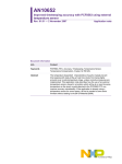
Fig. 1: Mounting the
module onto the DIN rail
2
1
3
Make sure that the voltage supply of the samos®PRO system is switched off.
Hang the device onto the DIN rail (1).
Connect the gateways directly onto the right side of the SP-SCON module of the
samos®PRO system. Up to two gateways per system are possible.
Ensure that the earthing spring contact (2) contacts the DIN rail such that it can electrically conduct.
Latch the module onto the DIN rail by pressing it lightly in the direction of the arrow (3).
Fig. 2: Installing the end
clips
If there are several modules, slide the modules together individually in the direction of
the arrow until the side plug connection latches in.
Install end clips on the left and right.
The following steps are necessary after mounting:
Complete the electrical connections (see section 4.2 “Electrical installation” on page 30)
Configuration (see section 4.3 “First configuration steps” on page 21 and the
samos®PLAN operating instructions (Wieland part no. BA000518).
Checking the installation (see the chapter on commissioning in the samos®PRO hardware
operating instructions, Wieland document no. BA000497).
Wieland Electric | BA000587 | 09/2009 (Rev. A)
19
Mounting and basic configuration of the gateways
4.1.2
Steps for dismantling the modules
Fig. 3: Removing the
removable terminals
Remove the removable terminals with the wiring and the end clips.
Fig. 4: Disconnecting the
plug connections
If there are several modules, slide the modules away from each other individually in the
direction of the arrow until the side plug connection is separated.
Fig. 5: Removing
modules from the DIN rail
Press the module downwards at the rear (1) and remove it from the DIN rail in the direction of the arrow while keeping it pressed down (2).
20
Wieland | BA000587 | 09/2009 (Rev. A)
Mounting and basic configuration of the gateways
4.2
Electrical installation
Switch the entire machine/system off line!
The system could start up unexpectedly while you are connecting the devices.
WA RNING
• The samos®PRO gateways fulfil the EMC requirements in accordance with the basic spe-
Notes
cification EN 61000-6-2 for industrial use.
• To ensure full electromagnetic compatibility (EMC), the mounting rail has to be connected to functional earth (FE).
• The control cabinet or assembly casing of the samos®PRO system must comply at least
with enclosure rating IP 54.
• Mounting in accordance with EN 50274.
• Electrical installation in accordance with EN 60204-1.
• The voltage supply of the devices must be capable of buffering brief mains voltage failures of 20 ms as specified in EN 60204-1.
• The voltage supply has to fulfil the regulations for extra-low voltages with safe separation (SELV, PELV) in accordance with EN 60664 and DIN 50178 (equipment of electrical
power installation with electronic devices).
• Ensure that all the modules of the samos®PRO system, the connected protective devices
as well as the voltage supplies are connected with the same GND plane. The GND of the
RS232 interface is connected internally to the GND of the supply of the main module
(A2).
• Connect all fieldbus and Ethernet cable shields directly at the control cabinet entrance to
the functional earth (FE).
4.3
First configuration steps
This chapter describes the basic steps you have to perform for the configuration of the
gateway:
• Establish a first connection between the gateway and a PC or laptop
• Upload or transfer of a configuration
• Verification of a configuration
4.3.1
Establishing a connection between gateway and PC
Connect a PC or notebook to the RS-232 interface of the SP-SCON.
Power on the samos®PRO System.
Open the samos®PLAN configuration tool installed on the PC.
Click on Edit com. interface settings to ensure the correct communication interface
has been selected. The following dialog appears:
Fig. 6: Com settings
dialog
Wieland Electric | BA000587 | 09/2009 (Rev. A)
21
Mounting and basic configuration of the gateways
To edit the settings click on the pencil icon to the right. The following dialog appears:
Fig. 7: Com settings
dialog
Modify the settings if required and click OK.
Click OK. The dialog closes.
Click on Connect to physical device. The samos®PLAN will search for connected
samos®PRO devices and load the hardware configuration into the hardware configuration dialog. Once all modules have been identified correctly, the samos®PLAN will ask
whether the configuration shall be uploaded.
Click Yes to upload the configuration.
As an example, the following hardware configuration may appear:
Fig. 8: Hardware configuration dialog
Click Disconnect to go into the offline mode if you want to change the configuration of
the samos®PRO modules.
4.3.2
Configuration of the gateways
For the configuration of the gateways please refer to the sections on the related gateway:
•
•
•
•
22
Section 5.2 “EtherNet/IP gateway” on page 37
Section 5.3 "Modbus TCP gateway" on page 50
Section 5.4 "PROFINET IO gateway" on page 59
Section 6.1 “PROFIBUS DP gateway” on page 71
Wieland | BA000587 | 09/2009 (Rev. A)
Mounting and basic configuration of the gateways
For the configuration of the TCP/IP interface of the Ethernet gateways, please refer to the
following sections:
• Section 5.1.1 “TCP/IP configuration interface” on page 25
• Section 5.1.2 “Ethernet TCP/IP socket interface” on page 28
For the configuration of the operational data (data transfer from and to the network),
please refer to chapter 7 “Layout and content of the process image” on page 83.
More information can be found in the samos®PLAN operating instructions (Wieland part no.
BA000518).
4.3.3
Transfer of a configuration
Once you have finished the configuration, you have to transfer the configuration to your
samos®PRO system. In order to transfer a configuration, perform the following steps:
Click Connect to go online. The samos®PLAN connects to the samos®PRO system.
Click Transfer to transfer the configuration to the samos®PRO system.
Depending on your current user level, you will be prompted to log on as authorized client
to be able to transfer a configuration. For details please see the samos®PLAN operating
instructions.
Note
Once the transfer has been completed, you will be asked whether you want to run the
CPU module. Depending on your choice, click Yes or No to leave the dialog.
You can also start and stop the application in the Hardware configuration view using the
Run application or Stop application buttons while the project is online.
Note
More information can be found in the samos®PLAN operating instructions (Wieland part no.
BA000518).
4.3.4
Verification of a configuration
After the configuration has been transferred successfully, the samos®PRO system can be
verified. To this purpose, the downloaded configuration data are read back out from the
samos®PRO system and compared with the project data. If they match, the data are displayed in a report. If the user confirms that they are correct, the system is considered to be
verified.
In the Hardware configuration view, click on the Upload and Verify configuration
button. A report of the current configuration will be generated.
Click Yes below at the question Mark device as verified? if the displayed configuration
is the expected configuration. The system is then considered to be verified.
• You have to be logged in as authorized user in order to mark the configuration as “veri-
Notes
fied”.
• If the verification is completed successfully, a “Read in and compare” report that provides the most important project information is created subsequently. You can print out
or store this report.
• The status verified/not verified is indicated in the lower right-hand corner of the samos®PLAN and by the CV LED at the samos®PRO main module lighting up.
Wieland Electric | BA000587 | 09/2009 (Rev. A)
23
Mounting and basic configuration of the gateways
• Only if the device and the corresponding configuration have been marked as verified, the
“Auto Start mode” is active in the configuration of the main module. If the configuration
is not set to verified after power up, the system stays in Idle mode (CV LED on the SPSCON module flashing) and the system needs to be set to Run mode using the samos®PLAN.
• If differences between the project data and the read-back configuration data are detected, a corresponding message including information about possible actions is displayed.
Verification of the configuration is not possible then. Observe the information in the error
message for the further procedure. Terminate the dialog box by clicking Close.
• If you change a verified configuration, the status is reset to “not verified”.
Exception: If you make only non safety-related changes such as modifying the gateway
name, the gateway’s IP address or the port number for a TCP/IP socket connection, the
configuration status remains “verified”.
More information can be found in the samos®PLAN operating instructions (Wieland part no.
BA000518).
4.3.5
Upload of a configuration
When in online mode, you can upload a configuration from the connected samos®PRO
system:
Click on Upload. The current configuration of the samos®PRO system will be loaded into
the samos®PLAN and can be edited after going offline.
24
Wieland | BA000587 | 09/2009 (Rev. A)
Ethernet gateways
5
Ethernet gateways
This chapter describes the following samos®PRO gateways:
• EtherNet/IP gateway (SP-EN-IP)
• Modbus TCP gateway (SP-EN-MOD)
• Profinet IO gateway (SP-EN-PN)
5.1
Common features of the Ethernet gateways
5.1.1
TCP/IP configuration interface
The samos®PRO Ethernet gateways offer a TCP/IP configuration interface which allows the
configuration of the samos®PRO System over Ethernet TCP/IP. This runs parallel to the
Ethernet TCP/IP or other Ethernet protocols.
Do not connect to the samos®PRO system via the RS-232 and the Ethernet interface
at the same time!
The samos®PRO system can only communicate with one instance of the samos®PLAN at one
time. Connecting to the samos®PRO system using multiple instances of the Designer, either
on a single PC or multiple PCs, may result in inconsistencies of the configuration and the
diagnostics as well as in operational errors. This applies to both RS-232 and Ethernet connections equally.
WA RNING
In order to configure a gateway for TCP/IP configuration for the first time, perform the
following steps:
Step 1: Assign an IP address
Connect a PC or notebook to the RS-232 interface of the SP-SCON.
Power on the samos®PRO System.
Open the samos®PLAN configuration tool installed on the PC and load the hardware configuration including the gateway.
If your project is online, click on the Disconnect button to go offline.
Click on the Gateway button above the main window and select the desired gateway.
Click on Gateway configuration on the left hand menu. The following dialog appears:
Wieland Electric | BA000587 | 09/2009 (Rev. A)
25
Ethernet gateways
Fig. 9: Gateway configuration dialog
On the left side of the dialog you will find the area for the gateway IP configuration.
If desired, enter a Device name for the samos®PRO gateway.
Enter a valid IP address, for the samos®PRO gateway, and if required a valid Subnet
mask and a valid IP address for a Default gateway.
Or:
If your network uses a DHCP server, activate the DHCP checkbox.
Click Connect to go online and transfer the configuration to the samos®PRO system.
Notes:
• If your project is online, you can use the Read IP address button at the upper left corner
of the gateway IP configuration area to retrieve the current IP settings of the gateway.
• The out-of-the-box default IP address of the gateway is 192.168.250.250. You can find
the default IP address also on the type label of the gateway.
Step 2: Add a TCP/IP profile to your project
Connect one of the two Ethernet ports of the gateway with your Ethernet network using
a shielded Ethernet cable.
Connect a PC (or notebook) to the same Ethernet network. Ensure the IP address settings of the PC match the network setup.
Note
You can also connect your PC directly to one of the two Ethernet ports of the gateway. In
this case, you can either adapt the IP address settings of your PC or the IP address settings
of the gateway to match the other device’s IP setup.
Open the samos®PLAN configuration tool installed on the PC and load the hardware configuration including the gateway.
If your project is online, click on the Disconnect button to go offline.
Click on Com Settings. The following dialog appears:
26
Wieland | BA000587 | 09/2009 (Rev. A)
Ethernet gateways
Fig. 10: Com settings
dialog
Click on Add TCP/IP Profile. The following dialog appears:
Fig. 11: Add TCP/IP
Profile dialog
Click on Scan to search for samos®PRO gateways on your Ethernet network. Gateways
located will be displayed as shown in the dialog below. The IP address will be displayed
as well as MAC address and device name.
Fig. 12: Add TCP/IP
Profile dialog after scan
has been performed
Select the gateway that you want to use as entry point.
Enter a name for the entry point to the Entry name edit field.
Click OK. The entry point has now been created and is shown in the connection dialog:
Wieland Electric | BA000587 | 09/2009 (Rev. A)
27
Ethernet gateways
Fig. 13: Connection
settings dialog with new
TCP/IP entry point
In order to use this entry point, it needs to be activated.
Click on the Activate Entry Point icon (white arrow in green circle) on the far right. The
entry point will then be activated and marked as such:
Fig. 14: Connection
settings dialog with new
TCP/IP entry point
activated
Click OK. All communication to the samos®PRO system will now happen via TCP/IP. In
order to use the entry point via the serial interface again, you will have to re-activate it.
The port number for the TCP/IP configuration interface is pre-set to port 9000 and can not
be changed.
Note
Step 3: Connect via TCP/IP
Click on the Connect button to go online.
5.1.2
Ethernet TCP/IP socket interface
Each samos®PRO Ethernet gateway supports a total number of four TCP/IP socket interfaces. This allows up to four different applications to communicate with the gateway at the
same time over Ethernet TCP/IP. The gateway’s proprietary network interface (e.g. Modbus
TCP) runs in parallel and its configuration or usage does not interact with the TCP/IP socket
configuration as it happens independently on separate samos®PLAN pages.
WA RNING
Do not use the same output data set number for two different PLC connections or
TCP/IP sockets!
The output data set can be written to the Ethernet gateways in parallel by all communication interfaces or TCP/IP sockets (e.g. Modbus TCP and Ethernet TCP/IP), if they use the
same output data set number. In that case the last message overrides data received earlier.
The gateway processes the data of a samos®PRO system and makes it available in different
compilations, the data sets. These data sets are available over the TCP/IP interface. For a
28
Wieland | BA000587 | 09/2009 (Rev. A)
Ethernet gateways
detailed description of the data sets please refer to section 3.2 “Data transmitted into the
network (network input data sets)” on page 12.
In order to configure the Ethernet TCP/IP socket interface, perform the following steps:
Open the samos®PLAN and load the hardware configuration including the gateway.
Click on the Gateway button above the main window and select the respective gateway
to open the gateway configuration dialog.
Click on TCP/IP configuration on the left hand menu. The following dialog appears:
Fig. 15: TCP/IP
configuration dialog
Configuration of the TCP/IP interface — who establishes the connection
If the samos®PRO gateway shall connect to the external application, perform the following
configuration steps:
Activate the Connect to radio button.
Set IP Address to the IP address of the computer the application is running on.
Enter the port number of the application for Port.
The configuration is considered faulty if either the connect socket port and/or the connect
IP address is zero when in Connect mode.
Note
If the external application shall connect to the samos®PRO gateway, perform the following
configuration steps:
Activate the Listen on radio button.
Enter the Port number for the application.
• Suggested port numbers are 9100 to 9103 (default values).
• Port 0 and port 9000 are reserved and can not be used (faulty configuration).
• Port numbers 0 to 1023 are managed by the Internet Assigned Numbers Authority
Notes
(IANA) and can not be used. See http://www.iana.org/assignments/port-numbers.
Finally, determine how the data is transferred. Follow the steps outlined in the following
section.
Wieland Electric | BA000587 | 09/2009 (Rev. A)
29
Ethernet gateways
Data transfer method — how the data is transferred
Whenever the TCP/IP socket connection has been established (either by an application on
a PC or by the gateway itself), there are two possible methods how the data sets can be
transferred:
• The application requests the data set(s) per command message (Application requests
(Polling) mode),
or
• the gateway auto-updates the data sets as per configuration (Gateway writes to Address/Port (Auto update) mode).
For both methods there are two update modes how the gateways update the data:
• Change of state (COS): when any data of the input data set change status.
• Automatic update: data will be sent according to the configured update rate in ms.
Note
If automatic update is enabled, a change of state will trigger an immediate update of the
data as well, regardless of the set update interval. I.e. COS is always active.
For both methods the following structure of messages applies.
General telegram structure
The request/response message (e.g. telegram) is structured as shown below:
0
1
…
…
…
…
…
…
…
Command Parameter(s)
(content depends on type of command)
Tab. 7: Telegram structure
Parameter
Command
Length
WORD
Parameter(s)
Length determined by
command
Length determined by
command
Data
…
…
…
…
Data
…
n
Description
0hex = Undefined (no command)
Polling mode specific
00F1hex = Input data set(s) request message
001Fhex = Input data set(s) response message
Auto-update specific
00E1hex = Auto update control
001Ehex = Auto update control response
002Ehex = Auto update input data set(s) message
Digital outputs read/write
00F2hex = Write output data set settings
002Fhex = Response to write output data set settings
As defined in specific command
As defined in specific command
Error response to invalid messages
The gateway will set the most significant bit of the command word in the event that an
invalid or improperly formatted message is received.
30
Wieland | BA000587 | 09/2009 (Rev. A)
Ethernet gateways
Parameter
Command
Length
WORD
Following
data
Length determined by
command
Description
Bit 15 of received command will be set
(i.e. command of 00F2hex would become 80F2hex)
Unchanged. Returned as it was received
Tab. 8: Error response
message
Application requests (Polling) mode
In this mode the gateway will only send any data upon request (e.g. polling). Therefore the
application shall send request telegrams as per definition below and the gateway will respond with telegrams structured as per definition below.
Get input data set(s)
The request message is sent by an application to the gateway. The request message telegram shall be structured as shown below:
Parameter
Command
Request
data set 1
Request
data set 2
Request
data set 3
Request
data set 4
Length
WORD
WORD
WORD
WORD
WORD
Value
00F1hex = Data set(s) request message
0 = Do not send data set 1
1 = Send data set 1
0 = Do not send data set 2
1 = Send data set 2
0 = Do not send data set 3
1 = Send data set 3
0 = Do not send data set 4
1 = Send data set 4
Tab. 9: Get data set(s)
request
The response message is returned to the application by the gateway. The response message telegram will be structured as shown below:
Parameter
Command
Data set 1
length
Data set 2
length
Data set 3
length
Data set 4
length
Data set(s)
data
Length
WORD
WORD
WORD
WORD
WORD
Array of
bytes
Value
00F1hex = Data set(s) response message
0 = Data set not returned in data set(s) data field
Non-zero = Length of data set
0 = Data set not returned in data set(s) data field
Non-zero = Length of data set
0 = Data set not returned in data set(s) data field
Non-zero = Length of data set
0 = Data set not returned in data set(s) data field
Non-zero = Length of data set
Data set(s) information
Tab. 10: Get data set(s)
response
Write output data sets
The following command message is sent by the application to the gateway to write to the
output data sets:
Wieland Electric | BA000587 | 09/2009 (Rev. A)
31
Ethernet gateways
Tab. 11: Write output
data set setting command
Parameter
Command
Output data
set 1 length
Output data
set 2 length
Output data
set 3 length
Output data
set 4 length
Output data
set 5 length
Data set(s)
data
Length
WORD
WORD
WORD
WORD
WORD
WORD
Array of
bytes
Value
00F2hex = Set output data set(s) command message
0 = Output data set not included in data set(s) data field
Non-zero = Length of data set
0 = Output data set not included in data set(s) data field
Non-zero = Length of data set
0 = Output data set not included in data set(s) data field
Non-zero = Length of data set
0 = Output data set not included in data set(s) data field
Non-zero = Length of data set
0 = Output data set not included in data set(s) data field
Non-zero = Length of data set
Data set(s) information
The response message is returned to the application by the gateway. The response message telegram is structured as shown below:
Tab. 12: Write output
data set setting response
Parameter
Command
Length
WORD
Status
WORD
Value
002Fhex = Response to write output data set settings message
0 = Success. Output data sets written correctly
1 = Error — Can not write output data sets due to either:
Loss of backplane communication
Incorrect routing information
Configuration via samos®PLAN tool
In order to configure the Application requests (Polling) mode of the gateway via the
samos®PLAN tool, perform the following steps:
Open the samos®PLAN and load the hardware configuration including the gateway.
Click on the Gateway button above the main window and select the respective gateway
to open the gateway configuration dialog.
Click on TCP/IP configuration on the left hand menu. The following dialog appears:
32
Wieland | BA000587 | 09/2009 (Rev. A)
Ethernet gateways
Fig. 16: TCP/IP
configuration for
Application requests
(Polling) mode
Check the Listen on checkbox.
Enter the Port number on which the application will connect.
Select the update mode: Enable COS update or Enable auto update and COS.
If you have selected Enable auto update and COS, select the Update rate in ms.
Select which data sets shall be updated: Check the Update Dataset n checkbox.
Gateway writes to Address/Port (Auto update) mode
The gateway can be configured to automatically update the data set information (i.e. the
application does not need to send any request messages as it would do in polling mode)
once the connection to the application has been made.
The configuration settings are available via the samos®PLAN configuration tool or via the
TCP/IP interface itself. Using one interface does not disable the other: The auto update
mode could be enabled via samos®PLAN and disabled via TCP/IP command, for example.
Configuration via TCP/IP interface
This command message is sent by an application to the gateway to configure the auto update mode. This message can be used to either disable or enable the auto update mode
directly through the TCP/IP interface.
Wieland Electric | BA000587 | 09/2009 (Rev. A)
33
Ethernet gateways
Tab. 13: Auto update
mode configuration
command
Note
Parameter
Command
Request data set 1
Request data set 2
Request data set 3
Request data set 4
Heartbeat
mode update
rate
Length
WORD
WORD
WORD
WORD
WORD
WORD
Value
00E1hex = Auto update control
0 = Do not send data set 1
1 = Send data set 1
0 = Do not send data set 2
1 = Send data set 2
0 = Do not send data set 3
1 = Send data set 3
0 = Do not send data set 4
1 = Send data set 4
0 = Disable heartbeat messages
Non-zero = Enable heartbeat message at specified rate in ms.
Minimum = 40 ms
Auto update is disabled if all Request Input Data Set flags are set to zero.
The response message returned to the application by the gateway:
Tab. 14: Auto update
mode configuration
response
Parameter
Command
Length
WORD
Value
001Ehex = Response to the auto update control message
Configuration via samos®PLAN tool
In order to configure the Gateway writes to Address/Port (Auto update) mode of the
gateway via the samos®PLAN tool, perform the following steps:
Open the samos®PLAN and load the hardware configuration including the gateway.
Click on the Gateway button above the main window and select the respective gateway
to open the gateway configuration dialog.
Click on TCP/IP configuration on the left hand menu. The following dialog appears:
Fig. 17: TCP/IP
configuration for auto
update
Check the Connect to checkbox.
Enter the IP Address and the Port number the gateway shall write to.
Select the update mode: Enable COS update or Enable auto update and COS.
34
Wieland | BA000587 | 09/2009 (Rev. A)
Ethernet gateways
If you have selected Enable auto update and COS, select the Update rate in ms.
Select which data sets shall be updated: Check the Update Dataset n checkbox.
Normal operation
The following message is sent from the gateway to the application while operating in auto
update mode.
Parameter
Command
Data set 1
length
Data set 2
length
Data set 3
length
Data set 4
length
Data set(s)
data
5.1.3
Length
WORD
WORD
WORD
WORD
WORD
Array of bytes
(length dependent on set
definition)
Value
002Ehex = Auto update data set(s) message
0 = Data set not returned in data set(s) data field
Non-zero = Length of data set
0 = Data set not returned in data set(s) data field
Non-zero = Length of data set
0 = Data set not returned in data set(s) data field
Non-zero = Length of data set
0 = Data set not returned in data set(s) data field
Non-zero = Length of data set
Data set(s) information. Details see section 3.2 “Data
transmitted into the network (network input data sets)” on
page 12 and chapter 7 “Layout and content of the process
image” on page 83.
Tab. 15: Auto update
mode normal operation
message
TCP/IP process image example
The following example shows a possible process image sent by a SP-EN-IP gateway via
TCP/IP in auto update mode:
Byte values (hex)
Part of message
Meaning
00 2E
Command
Auto update data sets (see Tab. 15)
00 32
Command parameters
Length of data set 1: 50 bytes
00 20
Length of data set 2: 32 bytes
00 3C
Length of data set 3: 60 bytes
00 3C
03 FF 03 03
C0
Length of data set 4: 60 bytes
Data set 1
(default byte assignments,
see Tab. 4)
Logic results 1-4
Input values module 1:
C0 = 11000000 = Inputs I8 and I7 Active
03
Input values module 2:
03 = 00000011 = Inputs I2 and I1 Active
3F 05
05 05 00 00
00 00 00 00
Input values module 3-12
00 00 00 00
00 00 00 00
00 00 00 00
Output values module 1-12
00 00 00 00
00 00 00 00
00 00 00 00
00 00 00 00
00 00 00 00
00 00
Not assigned
52 A1 10 4C
52 A1 10 4C
Tab. 16: TCP/IP process
image example
Data set 2
(see Tab. 4)
00 00 00 00
Overall CRC (same as system CRC)
System CRC
Reserved
00 00 00 00
00 00 00 00
00 00 00 00
00 00 00 00
00 00 00 00
FF FF FF FF
Data set 3
Wieland Electric | BA000587 | 09/2009 (Rev. A)
Status module 0 (SP-SCON): OK
35
Ethernet gateways
Byte values (hex)
Part of message
Meaning
FF FF FF FF
(see Tab. 4 and Tab. 5)
Data set 3 data is transferred
in Big Endian format, i.e. in
32 bit double word format
with the most significant
byte placed in the leftmost
position.
Status module 1 (e.g. SP-SDI): OK
FD FB FF FF
FF FF FF FF
FF FF FF FF
FF FF FF FF
FF FF FF FF
Status modules 3-6: OK
FF FF FF FF
FF FF FF FF
FF FF FF FF
FF FF FF FF
FF FF FF FF
FF FF FF FF
Status modules 7-12 (no modules present)
FF FF FF FF
Status module 13 (e.g. SP-EN-IP): OK
FF FF FF FF
Status module 14 (no module present)
00 00 00 00
00 00 00 00
00 00 00 00
00 00 00 00
00 00 00 00
00 00 00 00
00 00 00 00
00 00 00 00
00 00 00 00
00 00 00 00
00 00 00 00
00 00 00 00
00 00 00 00
00 00 00 00
00 00 00 00
36
Status module 2 (e.g. SP-SDIO):
Byte 0: FF = 11111111: No errors
Byte 1: FF = 11111111: No errors
Byte 2: FB = 11111011: Input 3 external test
signal failure
Byte 3: FD = 11111101: Output 1 stuck-at-low
error
Data set 4
Reserved
Wieland | BA000587 | 09/2009 (Rev. A)
Ethernet gateways
5.2
EtherNet/IP gateway
The following samos®PRO gateway can be used for EtherNet/IP: SP-EN-IP.
You will find the EDS file and device icon for PLC interfacing
• on www.wieland-electric.com (go to "Support/Download Center")
• in the samos®PLAN program folder on your hard disc (default installation folder is
“C:\programs\Wieland\samosPRO\DeviceDescriptions\...”)
The samos®PRO EtherNet/IP gateway SP-EN-IP supports only EtherNet/IP explicit messaging. Class 1 messaging is not supported.
5.2.1
Interfaces and operation
The SP-EN-IP is equipped with an integrated three-port switch for connection with the
Ethernet network. Two RJ45 sockets are available for the connection. The switch functionality allows the SP-EN-IP to be used for connection to another Ethernet component (e.g.
connection to a notebook) without having to interrupt the Ethernet connection to the network.
Fig. 18: Interfaces and
display elements of the
SP-EN-IP
RJ45 Ethernet socket
LED power supply (green)
LED network activity for Ethernet port 1
or 2 (green)
LED MS (red/green)
RJ45 Ethernet socket
LED
PWR
LINK/ACT 1
LINK/ACT 2
Green
Meaning
No power supply
Power supply switched on
Green
No Ethernet connection
Ethernet connection active, no data transmission
Green
MS
Green
Ethernet connection active, data transmission
Power-up
Executing (live process data from/to CPU)
Green
1 Hz: Idle
Red
1 Hz: Configuring/configuration required
2 Hz: Critical fault on gateway
Critical fault on another module
Red
Red/Green
Tab. 17: Meaning of the
LED displays of the SPEN-IP
Executing, but Ethernet communication not established
or faulty
Symbol description:
: LED off
Green: LED lights up green
Wieland Electric | BA000587 | 09/2009 (Rev. A)
Red: LED flashes red
37
Ethernet gateways
Note
Error elimination is described in section 5.2.6 “Diagnostics and troubleshooting” on page
48.
Power-up sequence
On power up, the following LED test sequence is performed:
•
•
•
•
LED MS
LED MS
LED MS
LED MS
5.2.2
Off for 6 s.
Red for 0.25 s.
Green for 0.25 s.
Off.
Basic configuration — assigning a device name and IP address
Configuration of the SP-EN-IP is performed via the samos®PLAN tool.
Via samos®PLAN tool
Open the samos®PLAN and load the hardware configuration including the EtherNet/IP
gateway.
Click on the Gateway button above the main window and select the SP-EN-IP to open
the gateway configuration dialog.
Click on Gateway configuration on the left hand menu. The following dialog appears:
Fig. 19: Gateway
configuration dialog
If desired, change the Device name for the samos®PRO gateway.
Enter a valid IP address for the samos®PRO gateway, and if required a valid Subnet
mask and a valid IP address for a Default gateway.
Click Connect to go online and download the configuration to the samos®PRO system.
38
Wieland | BA000587 | 09/2009 (Rev. A)
Ethernet gateways
5.2.3
Configuration of the interface to the PLC — how the data are transferred
Transfer methods
The configuration steps in this section specify how the data to the higher-level PLC are
transferred. In general, there are two different transfer methods available for both transfer
directions such as samos®PRO to Network and Network to samos®PRO:
• Gateway writes to Tag/File and/or Gateway reads from Tag/File — The SP-EN-IP
gateway operates as master. It writes the data into and/or reads from the PLC memory.
• PLC requests and/or PLC writes — The SP-EN-IP gateway operates as slave. The PLC
requests the data from the gateway and/or writes the data to the gateway.
Both methods can be mixed. E.g. it is possible to configure the gateway as master for the
samos®PRO to Network direction (option Gateway writes to Tag/File activated) while it
operates at the same time as slave for the Network to samos®PRO direction (option PLC
writes activated).
Number of possible connections
The number of possible connections to the PLC depends on whether the SP-EN-IP is operated as master or slave. Depending on the setting, up to 128 PLCs can address the SP-ENIP at the same time.
Operating mode of the SP-EN-IP
Maximum connections
Tab. 18: Number of
possible connections
Rx (To PLC) Transfer mode: Gateway writes to Tag/File
Rx and Tx: 1
Tx (From PLC) Transfer mode: Gateway reads from Tag/File
Rx (To PLC) Transfer mode: Gateway writes to Tag/File
Tx (From PLC) Transfer mode: PLC writes
Rx: 1
Tx: 127
Rx (To PLC) Transfer mode: PLC requests
Rx: 127
Tx (From PLC) Transfer mode: Gateway reads from Tag/File Tx: 1
Rx (To PLC) Transfer mode: PLC requests
Tx (From PLC) Transfer mode: PLC writes
Rx and Tx: 128
Configuration process
The following table outlines the configuration process depending on the transfer method:
Gateway is master (Gateway writes to Tag/File and/or Gateway reads from Tag/File)
To do in the gateway configuration
(via samos®PLAN tool)
To do in the PLC program and/or EtherNet/IP
network configuration tool
Select which data shall be written to/read from
the PLC
—
Define where in the PLC memory the selected
data shall be written to: Enter tag names.
Example: InDataSet1
And/or define where in the PLC memory the selected data shall be read from: Enter tag names.
Example: OutDataSet1
Define exactly the same tag names in the PLC
program.
Example:
InDataSet1 INT[25]
OutDataSet1 INT[5]
The data type shall be INT.
Select how often this data shall be transmitted.
—
Tab. 19: Configuration
guideline — gateway as
master
Define where the data shall be read from/written —
to in the EtherNet/IP network: Enter the IP address
and controller slot number of the PLC.
Wieland Electric | BA000587 | 09/2009 (Rev. A)
39
Ethernet gateways
Tab. 20: Configuration
guideline — gateway as
slave
Gateway is slave (PLC requests and/or PLC writes)
To do in the gateway configuration
(via samos®PLAN tool)
To do in the PLC program and/or EtherNet/IP
network configuration tool
—
Download and install the SP-EN-IP EDS file from
www.wieland-electric.com ("Support/Download
Center")
—
Integrate the SP-EN-IP into the EtherNet/IP network via network configuration tool (i.e. RSNetworx).
—
Program the explicit message “Get_Attribute_...”
or “Set_Attribute_...” in the PLC program to
read/write data from/to the gateway
—
Program the trigger for sending the explicit messages.
Method 1: Gateway writes to/reads from Tag/File — SP-EN-IP gateway writes the
data into/reads the data from the PLC memory
In this operating mode the SP-EN-IP as a master writes the data of all activated data sets
into the specified memory areas of the PLC. The only task for the PLC programmer is to
de-fine a controller tag name which matches the gateway configuration tag name.
In order to configure the gateway to be master, perform the following steps:
Open the samos®PLAN and load the hardware configuration including the EtherNet/IP
gateway.
Click on the Gateway button above the main window and select the SP-EN-IP to open
the gateway configuration dialog.
Click on Gateway configuration on the left hand menu. The following dialog appears:
Fig. 20: Gateway
configuration dialog
Within the Gateway configuration dialog, select the transfer method by activating
Gateway writes to Tag/File for the samos®PRO to Network direction and Gateway
reads from Tag/File for the Network to samos®PRO direction.
Select which data shall be written to/read from the PLC by checking the checkbox for
the required data set.
40
Wieland | BA000587 | 09/2009 (Rev. A)
Ethernet gateways
Define where in the PLC memory the selected data shall be written to or read from:
Enter tag names into the Tag/File name edit fields (max. 20 characters).
Select Write all Sets in one Tag if all data sets shall be written into one tag in the PLC
memory. In this case, the tag defined for data set 1 will be used.
Define how often the data shall be transmitted to the PLC:
− Select Enable Update COS (update on change of state) if the SP-EN-IP is to update
the data in the PLC immediately when changes occur in the data sets.
− Select Enable heartbeat interval to activate updating of the selected data sets with
the set Heartbeat rate in ms.
− Both options may be selected at the same time.
Define how often the data shall be read from the PLC:
− Enter a Heartbeat rate in ms to activate updating of the selected data sets with the
set time.
Define where the data shall be read to/written from in the EtherNet/IP network: Enter
the IP address and controller Slot number of the PLC.
The configuration is considered faulty, if the PLC IP address is zero and either Gateway
writes to Tag/File for the samos®PRO to Network direction and/or Gateway reads from
Tag/File for the Network to samos®PRO direction is activated.
Note
The Max. PLC update rate (ms) defines the maximum rate (the minimum time interval)
for transferring the data sets to and from the PLC. Settings occur dependent on the PLC
processing speed. Minimum = 10 ms, maximum = 65535 ms. The default value of 40
ms is suitable for most PLCs.
• If the value entered for the Max. PLC update rate is greater than the Heartbeat rate set
Notes
for writing to or reading from the PLC, the heartbeat rate will be automatically increased
(i.e. slowed down) to this value.
• All data sets are transferred to the PLC in 16 bit integer format with the first byte placed
in the most significant, or leftmost byte of the integer.
Click Connect to go online and download the configuration to the samos®PRO system.
Open the PLC programming tool.
Define the PLC tag names as previously configured in the samos®PRO EtherNet/IP gateway. Fig. 21 shows an example for the definition of tag names in a PLC program written
with RSLogix:
Fig. 21: Example of tag
names in a PLC program
• Tag names for Allen Bradley SLC/PLC-5 PLCs must begin with a “$” (i.e. $N10:0).
• Tag names for Allen Bradley MicroLogix PLCs must begin with a “#” (i.e. #N10:0).
Wieland Electric | BA000587 | 09/2009 (Rev. A)
Notes
41
Ethernet gateways
Method 2: Polling mode — PLC requests the data from/PLC writes the data to the
SP-EN-IP
In this operating mode the SP-EN-IP operates as slave. It sends the data to the PLC upon
request and the PLC writes the data to the gateway. If this operating mode is desired:
Open the samos®PLAN and load the hardware configuration including the EtherNet/IP
gateway.
Click on the Gateway button above the main window and select the SP-EN-IP to open
the gateway configuration dialog.
Click on Gateway configuration on the left hand menu. The following dialog appears:
Fig. 22: Gateway
configuration dialog
Within the Gateway configuration dialog, select the transfer method by activating PLC
requests for the samos®PRO to Network direction, PLC writes for the Network to
samos®PRO direction.
Select which data shall be requested or written by the PLC by checking the checkboxes
for the required data sets.
Click Connect to go online and download the configuration to the samos®PRO system.
Program the explicit messaging in the PLC.
Polling data sets via explicit messaging
The SP-EN-IP supports two vendor specific objects which can be polled via explicit messaging:
• The Full Data Set Transfer object allows to poll for each of the data sets. There is one
instance where each attribute represents a data set.
• The Individual Input Data Set Transfer object allows to poll for the individual data set
parameters. There is one instance per data set and each attribute represents one byte of
the data set.
42
Wieland | BA000587 | 09/2009 (Rev. A)
Ethernet gateways
Full Data Set Transfer object definition (72 HEX – one instance)
The vendor specific Full Data Set Transfer object defines the attributes by which the PLC
can:
• Request the complete input data set information from the SP-EN-IP.
• Write the complete output data set information to the SP-EN-IP.
Class attributes
Attribute ID
1
2
3
Name
Revision
Max. instance
Num. instances
Data type
UINT
UINT
UINT
Data value(s)
1
1
1
Access rule
Get
Get
Get
Tab. 21: Full Data Set
Transfer object (72hex)
class attributes
Instance attributes
These attributes provide access to input and output data sets. Get Attribute Single requests
for a specific input data set will return the input data set information. Get Attribute All requests will return all enabled input data sets.
All data set information will be returned in integer (16 bit word) format. For byte data, the
first byte will be placed in the most significant or leftmost byte of the integer and the second byte will be placed in the least significant or rightmost byte of the integer.
Attribute ID Name
samos®PRO to Network
1
Request input data set 1
specific data
2
Request input data set 2
specific data
3
Request input data set 3
specific data
4
Request input data set 4
specific data
Network to samos®PRO
5
Write the output data
set 1 specific data
6
Write the output data
set 2 specific data
7
Write the output data
set 3 specific data
8
Write the output data
set 4 specific data
9
Write the output data
set 5 specific data
Common services
Service code Implemented in class
01hex
0Ehex
10hex
02hex
Yes
Yes
No
No
Wieland Electric | BA000587 | 09/2009 (Rev. A)
Data type
Data value(s)
Access rule
Array of UINT
0-255
Get
Array of UINT
0-255
Get
Array of UINT
0-255
Get
Array of UINT
0-255
Get
Array of UINT
0-255
Set
Array of UINT
0-255
Set
Array of UINT
0-255
Set
Array of UINT
0-255
Set
Array of UINT
0-255
Set
Implemented in
instance
Yes
Yes
Yes
Yes
Service name
Tab. 22: Full Data Set
Transfer object (72hex)
instance attributes
Tab. 23: Full Data Set
Transfer object (72hex)
common services
Get_Attributes_All
Get_Attribute_Single
Set_Attribute_Single
Set_Attribute_All
43
Ethernet gateways
Individual Input Data Set Transfer object definition (73 HEX – one instance per data
set)
The vendor specific Individual Input Data Set Transfer object defines the attributes by
which the PLC can request either full input data sets or individual parameters within an
input data set.
Tab. 24: Individual Input
Data Set Transfer object
(73hex) class attributes
Tab. 25: Individual Input
Data Set Transfer object
(73hex) instance attributes
Tab. 26: Individual Input
Data Set Transfer object
(73hex) common services
Class attributes
Attribute ID
1
2
3
Name
Revision
Max instance
Num instances
Instance attributes
Attribute ID
Name
Request input
1 to n
data set specific
(dependent on
data
data set definition)
Common services
Service code
01hex
0Ehex
Data type
UINT
UINT
UINT
Data value(s)
1
4
4
Access rule
Get
Get
Get
Data type
SINT
Data value(s)
0-255
Access rule
Get
Implemented in
class
Yes
Yes
Implemented in
instance
Yes
Yes
Service name
Get_Attributes_All
Get_Attribute_Single
Instance attribute definitions
Attribute 1 to n — Request input data set specific parameters
These attributes return the input data set specific data arrays. Get Attribute Single requests for a specific input data set will return only the requested data set parameter information. Get Attribute All requests will return the entire data set.
The data set attributes, numbered from 1 to N, refer to each individual attribute of each
individual input data set. Each instance refers to a unique input data set and each input
data set has a unique attribute numbering scheme. The following tables reflect the attribute definitions for each input data set.
Get All Data Set Attributes request
All data set information will be returned in integer (16 bit word) format. For byte data, the
first byte will be placed in the least significant or rightmost byte of the integer and the
second byte will be placed in the most significant or leftmost byte of the integer.
Example:
For an input data set, the data will be returned as follows:
− IntegerArray[0]:
AABB (hex) –
AA = BYTE1; BB = BYTE2
− IntegerArray[1]:
CCDD (hex) –
CC = MED1; BB = MED2
MMNN (hex) –
MM = BYTE13; NN = BYTE14
−…
− IntegerArray[6]:
Note
44
The typical PC tools of Rockwell/Allen Bradley change this data format back to BBAA (hex)
format for visualisation purposes. Check your data for plausibility before putting your
samos®PRO system into operation.
Wieland | BA000587 | 09/2009 (Rev. A)
Ethernet gateways
Instance 1 – Input data set 1 attribute definitions
Attribute number
Data set parameter
1
Byte 0
2
Byte 1
…
…
50
Byte 49
Size
SINT
SINT
…
SINT
Tab. 27: Individual Input
Data Set Transfer object
(73hex) instance 1
attribute definitions
Instance 2 – Input data set 2 attribute definitions
Attribute number
Data set parameter
1
Overall CRC
2
System CRC (SCID)
3
Reserved
4
Reserved
5
Reserved
6
Reserved
7
Reserved
8
Reserved
Size
UDINT
UDINT
UDINT
UDINT
UDINT
UDINT
UDINT
UDINT
Tab. 28: Individual Input
Data Set Transfer object
(73hex) instance 2
attribute definitions
Instance 3 - Input data set 3 attribute definitions
Attribute number Data set parameter
1
Module status module 0
2
Module status module 1
…
…
15
Module status module 14
Size
UINT[2]
UINT[2]
…
UINT[2]
Tab. 29: Individual Input
Data Set Transfer object
(73hex) instance 3
attribute definitions
Instance 4 - Input data set 4 attribute definitions
Attribute number Data set parameter
1
Reserved
2
Reserved
…
…
15
Reserved
Size
UINT[2]
UINT[2]
…
UINT[2]
Tab. 30: Individual Input
Data Set Transfer object
(73hex) instance 4
attribute definitions
PLC-5/SLC/MicroLogix interface
The PLC-5, SLC and MicroLogix PLC interfaces are supported by:
• The same write to PLC functionality as provided to ControlLogix PLCs provided in the
Write-to-File receive method.
• PCCC based messages transferred via the PCCC object.
− SLC Typed Read Message.
− SLC Typed Write Message.
− PLC-5 Typed Read Message (Logical ASCII and Logical Binary address format).
− PLC-5 Typed Write Message (Logical ASCII and Logic binary address format).
• Normal PLC-5/SLC file naming conventions are used.
The primary differences between the PLC-5/SLC/MicroLogix interface and the ControlLogix
interfaces are:
• Polling is performed through the SLC and PLC-5 specific messages instead of accessing
the Data Transfer object.
• Data is written into files on the PLC, instead of tags as on ControlLogix PLCs.
While ControlLogix PLCs support the SLC and PLC-5 messages, using those messages on
ControlLogix PLCs is not recommended due to data size and performance considerations.
Wieland Electric | BA000587 | 09/2009 (Rev. A)
Note
45
Ethernet gateways
Receive communication methods
• Polling Receive Method
This method provides a polling method that allows the PLC to request data on a periodic
basis.
In this method, the input data set information is returned in the response to the data request message. The PLC requests data by accessing the corresponding data file address
on the SP-EN-IP with either a SLC typed read or PLC-5 typed read message.
The following restrictions apply to this method:
− The file location to receive the input data set on the PLC must be of type INTEGER and
large enough to contain the input data set table(s).
− If no data has been received on the SBUS+ for the specified module, all zeros will be
returned.
• Unsolicited – Write to File Receive Method
When it is determined that data received on the samos®PRO gateway’s SBUS+ interface
is to be sent to the PLC, the data is immediately written to a file location on the PLC.
The following restrictions apply to this method:
− The Receive Data Area File Name must have the same name as the file defined on the
PLC. For SLC and PLC-5 PLCs, all file names must be configured with a preceding “$”
(i.e $N10:0). For MicroLogix PLCs, all file names must be configured with a preceding
“#” (i.e # N10:0).
− The file on the PLC must be of type INTEGER and must be large enough to contain the
input data set table(s).
− Data will be written with the first byte placed in the MS byte location of the integer.
Example: aabb, ccdd, eeff, etc. where aa = byte 1, bb = byte 2, cc = byte 3, etc.
Transmit (From PLC) Data Transfer Methods
The SP-EN-IP will support the following methods of receiving or retrieving the output data
set(s) from the PLC.
• PLC Writes Method
This is the standard method where the PLC uses a message instruction to write the output data sets to the SP-EN-IP. With this method, the output data sets can be updated via
a PCCC message written to the corresponding file/address location on the SP-EN-IP.
• Read-from-File Transmit Method (Poll the PLC)
With this method, the SP-EN-IP will monitor the configured PLC memory location for
changes to the output data set(s). When a change is detected, the output data sets will
be processed accordingly.
The following restrictions apply to this method:
− The output data set file locations must be of INTEGER (16 bit word) format and must
be of sufficient length to contain the entire output data set.
− Data in the INTEGER file must be formatted with the first byte placed in the MS byte
location.
Example: aabb, ccdd, eeff, etc. where aa = byte 1, bb = byte 2, cc = byte 3, etc.
46
Wieland | BA000587 | 09/2009 (Rev. A)
Ethernet gateways
PLC-5 and SLC Messages
The following PCCC messages are supported for the PLC-5, SLC and MicroLogix PLCs:
Message type
SLC Typed Read
PCCC message
162
SLC Typed Write
170
PLC-5 Typed Read
104
PLC-5 Typed Write
103
Maximum message size
CLX: 242 SINTs (121 INTs)
SLC: 206 SINTs (103 INTs)
CLX: 220 SINTs (110 INTs)
SLC: 206 SINTs (103 INTs)
CLX: 234 SINTs (117 INTs)
SLC: 252 SINTs (126 INTs)
CLX: 226 SINTs (113 INTs)
SLC: 226 SINTs (113 INTs)
Both the PLC-5 and SLC Typed Read message can be used to retrieve all input data sets.
Address
N10:0
N11:0
N12:0
N13:0
N14:0
N20:0
N21:0
N22:0
N23:0
N24:0
N25:0
Description
All enabled input data sets data
Request input data set 1 data
Request input data set 2 data
Request input data set 3 data
Request input data set 4 data
Write all enabled output data sets
Write output data set 1 data
Write output data set 2 data
Write output data set 3 data
Write output data set 4 data
Write output data set 5 data
Access rule
Get
Get
Get
Get
Get
Set
Set
Set
Set
Set
Set
Data size (words)
16-1013)
25
16
30
30
5-254)
5
5
5
5
5
Tab. 31: Supported PCCC
messages for the PLC-5,
SLC and MicroLogix PLCs
Note
Tab. 32: Addressing for
the PLC-5/SLC messages
PLC-5/SLC Receive Data Message
The Receive Input Data Set Message format is as defined for each individual input data set.
Please refer to Tab. 4 and Tab. 5 in section 3.2 “Data transmitted into the network (network input data sets)” on page 12 for further details.
PCCC object (67 HEX – 1 instance)
The PCCC object provides the ability to encapsulate and then transmit and receive PCCC
messages between devices on an EtherNet/IP network. This object is used to communicate to SLC 5/05 and PLC-5 PLCs over EtherNet/IP.
Class attributes
Not supported.
Instance attributes
Not supported.
Instances
Supports instance 1.
3)
4)
Will correspond to all enabled input data sets.
Must correspond to all enabled output data sets. Example: If only output data sets 1 and 2 are enabled, then 10
words, (20 bytes), must be written. If all output data sets are enabled, then 25 words, (50 bytes), must be written.
Wieland Electric | BA000587 | 09/2009 (Rev. A)
47
Ethernet gateways
Tab. 33: PCCC object
(67hex) common services
Common services
Service code
Implemented in
class
No
4Bhex
Tab. 34: PCCC object
(67hex) request message
Message structure
Name
Length
Vendor
Serial number
CMD
STS
TNSW
FNC
PCCC_params
Tab. 35: PCCC object
(67hex) response message
Name
Length
Vendor
Serial number
CMD
STS
TNSW
EXT_STS
PCCC_params
Tab. 36: PCCC object
(67hex) supported PCCC
command types
CMD
0Fhex
0Fhex
0Fhex
0Fhex
5.2.4
for Execute_PCCC
Data type
USINT
UINT
UDINT
USINT
USINT
UINT
USINT
Array of USINT
FNC
67hex
68hex
A2hex
AAhex
Data type
USINT
UINT
UDINT
USINT
USINT
UINT
USINT
Array of USINT
Implemented in
instance
Yes
Service name
Execute_PCCC
Description
Length of requestor ID
Vendor number of requestor
ASA serial number of requestor
Command byte
0
Transport word
Function code
CMD/FMC specific parameters
Description
Length of requestor ID
Vendor number of requestor
ASA serial number of requestor
Command byte
Status byte
Transport word. Same value as request
Extended status (if error)
CMD/FMC specific result data
Description
PLC-5 write
PLC-5 read
SLC 500 protected read with 3 address fields
SLC 500 protected write with 3 address fields
TCP/IP configuration interface
See section 5.1.1 “TCP/IP configuration interface” on page 25.
5.2.5
Ethernet TCP/IP socket interface
See section 5.1.2 “Ethernet TCP/IP socket interface” on page 28.
5.2.6
Diagnostics and troubleshooting
For information how to perform diagnostics on the samos®PRO system please refer to the
operating instructions for the samos®PLAN software (Wieland part no. BA000518).
48
Wieland | BA000587 | 09/2009 (Rev. A)
Ethernet gateways
Error
Cause
Possible remedy
SP-EN-IP has no power supply.
The samos®PLAN tool does
SP-EN-IP is not in the same
not connect to the
samos®PRO gateway module physical network as the PC.
The PC is configured to another
subnet mask in the TCP/IP settings.
SP-EN-IP has already been configured once and has a fixed set
IP address or an IP address
assigned by a DHCP server that
is not recognised.
Establish the power supply.
Check the Ethernet wiring and network settings on the PC and correct
if necessary.
Set the subnet mask on the PC to
255.255.0.0 (factory setting of the
SP-EN-IP).
Check the communication settings
in the samos®PLAN.
SP-EN-IP does not supply
any data.
LED PWR Green
LED LINK/ACT /
Green
Red/Green
LED MS
SP-EN-IP is configured for data
transfer to PLC, but Ethernet
communication is not yet established or faulty.
Duplicate IP address detected.
Another device on the network
has the same IP address.
Minimum one Ethernet connection
needs to be established. Set up
Ethernet connection on PLC side,
check Ethernet cabling, check
Ethernet connection settings on PLC
and in the samos®PLAN. If no
Ethernet communication is required,
disable the Ethernet connections/PLC interfaces on the SP-ENIP.
Adjust IP address and power cycle
device.
SP-EN-IP does not supply
any data.
LED PWR Green
LED LINK/ACT /
Green
Red (1 Hz)
LED MS
Configuration required.
Configuration download is not
completed.
Configure the SP-EN-IP and
download the configuration to the
device.
Wait until the configuration
download has been completed.
SP-EN-IP does not supply
any data.
LED PWR Green
LED LINK/ACT /
Green
LED MS Green
No data set is activated.
No Ethernet communication
interface is enabled.
Activate at least one data set.
SP-EN-IP does not supply
any data.
LED PWR Green
LED LINK/ACT /
Green
Green (1 Hz)
LED MS
SP-EN-IP is in Idle mode.
CPU/application is stopped. Start
CPU (change into Run mode) .
SP-EN-IP functioned correctly after configuration, but
suddenly no longer supplies
data.
LED PWR Green
LED LINK/ACT /
Green
Red/Green
LED MS
SP-EN-IP is operated in slave
mode, the IP address is assigned
from a DHCP server. After the
SP-EN-IP or the DHCP server has
been restarted, a different IP
address that is unknown to the
PLC has been assigned to the
SP-EN-IP.
Either assign a fixed IP address to
the SP-EN-IP, or reserve a fixed IP
address for the SP-EN-IP in the
DHCP server (manual assignment by
means of the MAC address of the
SP-EN-IP).
SP-EN-IP/ samos®PRO system is in Critical fault mode.
LED PWR Green
LED LINK/ACT
Green
LED MS Red
SP-EN-IP is not plugged properly
into the other samos®PRO module.
Module connection plug is soiled
or damaged.
Other samos®PRO module has
internal critical error.
Plug the SP-EN-IP in correctly.
Clean the connecting socket/plug.
Repower the system.
Check the other samos®PRO modules.
SP-EN-IP is in Critical fault
mode.
LED PWR Green
LED LINK/ACT /
Green
Red (2 Hz)
LED MS
SP-EN-IP internal device error
CPU firmware version does not
support samos®PRO gateways.
Switch off the power supply of the
samos®PRO system and switch it on
again.
Check the diagnostics messages
with the samos®PLAN.
Use a CPU with the required firmware version (see section 2.2
“Correct use” on page 9).
If the error remains, replace the
gateway.
Tab. 37: Troubleshooting
for the SP-EN-IP
Symbol description:
: LED off
Green: LED lights up green
Wieland Electric | BA000587 | 09/2009 (Rev. A)
Red: LED flashes red
49
Ethernet gateways
5.3
Modbus TCP gateway
The following samos®PRO gateway can be used for Modbus/TCP: SP-EN-MOD.
The samos®PRO Modbus TCP gateway supports:
• Modbus TCP master and slave receive methods
• Ethernet TCP/IP socket interface, polling and auto update function
5.3.1
Interfaces and operation
The SP-EN-MOD is equipped with an integrated three-port switch for connection with the
Ethernet network. Two RJ45 sockets are available for the connection. The switch functionality allows the SP-EN-MOD to be used for connection to another Ethernet component
(e.g. connection to a notebook) without having to interrupt the Ethernet connection to the
network.
Fig. 23: Interfaces and
display elements of the
SP-EN-MOD
RJ45 Ethernet socket
LED power supply (green)
LED network activity for Ethernet port 1
or 2 (green)
LED MS (red/green)
RJ45 Ethernet socket
Tab. 38: Meaning of the
LED displays
LED
PWR
LINK/ACT 1
LINK/ACT 2
Green
Meaning
No power supply
Power supply switched on
Green
No Ethernet connection
Ethernet connection active, no data transmission
Green
MS
Green
Ethernet connection active, data transmission
Power-up
Executing (live process data from/to CPU)
Green
1 Hz: Idle
Red
1 Hz: Configuring/configuration required
2 Hz: Critical fault on gateway
Critical fault on another module
Red
Red/Green
Executing, but Ethernet communication not established
or faulty
Symbol description:
: LED off
Note
50
Green: LED lights up green
Red: LED flashes red
Error elimination is described in section 5.3.6 “Diagnostics and troubleshooting” on
page 57.
Wieland | BA000587 | 09/2009 (Rev. A)
Ethernet gateways
Power-up sequence
On power up, the following LED test sequence is performed:
• LED MS
• LED MS
• LED MS
• LED MS
5.3.2
Off for 6 s.
Red for 0.25 s.
Green for 0.25 s.
Off.
Basic configuration — assigning an IP address
Configuration of the SP-EN-MOD is performed via the samos®PLAN tool.
Via samos®PLAN tool
Open the samos®PLAN and load the hardware configuration including the Modbus TCP
gateway.
Click on the Gateway button above the main window and select the SP-EN-MOD to
open the gateway configuration dialog.
Click on Gateway Configuration on the left hand menu. The following dialog appears:
Fig. 24: Gateway
configuration dialog
Enter a valid IP address, Subnet mask and if required a valid IP address for a Default
gateway.
Click OK.
Click Connect to go online and download the configuration to the samos®PRO system.
5.3.3
Configuration of the Modbus TCP interface to the PLC — how the data is
transferred
Modbus TCP application characteristics:
• Support of standard Modbus TCP addressing conventions.
• Master and Slave receive methods
Wieland Electric | BA000587 | 09/2009 (Rev. A)
51
Ethernet gateways
Modbus TCP PLC requirements:
• The PLC must support the Modbus TCP protocol.
• The PLC must support the Read Holding Registers and Write Multiple Registers commands or, alternatively, the Read/Write Multiple Registers command.
The configuration steps in this section specify how the data to the higher-level PLC are
transferred.
In general, there are two different transfer methods available for each transfer direction
such as samos®PRO to Network and Network to samos®PRO:
• Polling receive method/PLC requests (gateway as slave)
This method provides a polling method that allows the PLC to request data on a periodic
basis. In this method, the data is returned in the response to the data request message.
The PLC requests data by accessing the receive data address on the SP-EN-MOD module with a Read Holding Registers message.
• Master receive method – Gateway writes to PLC (auto-update, gateway as master)
When it is determined that data received on the SP-EN-MOD module backplane interface
is to be sent to the PLC, the data is immediately written to a data memory location on
the PLC.
• Slave transmit method - PLC writes (gateway as slave)
In this method, the PLC will send write messages to the SP-EN-MOD module to set the
output data sets. To write to the output data sets, the PLC writes the data to specified
addresses.
• Master transmit method - Gateway reads from PLC (auto-update, gateway as master)
• In the master transmit mode, the SP-EN-MOD module will poll the PLC for the output
data set settings.
Note
The configuration is considered faulty, if the PLC IP address is zero and either the Read
Transfer mode and/or the Write Transfer mode is set to Master.
The number of possible connections to the PLC depends on whether the SP-EN-MOD is
operated as a master or slave. Depending on the setting, up to 32 PLCs can address the
SP-EN-MOD at the same time.
Tab. 39: Number of
possible connections
Operating mode of the SP-EN-MOD
Maximum connections
Rx (To PLC) transfer mode: Master
Tx (From PLC) transfer mode: Master
Rx and Tx: 1
Rx (To PLC) transfer mode: Master
Tx (From PLC) transfer mode: Slave
Rx: 1
Tx: 31
Rx (To PLC) transfer mode: Slave
Tx (From PLC) transfer mode: Master
Rx: 31
Tx: 1
Rx (To PLC) transfer mode: Slave
Tx (From PLC) transfer mode: Slave
Rx and Tx: 32
The following table outlines a guideline to the configuration process depending on the
transfer method:
Gateway is master
Tab. 40: Configuration
guideline — gateway as
master
52
To do in the gateway configuration (via
samos®PLAN tool)
To do in the PLC program and/or Modbus TCP
network configuration tool
Select Gateway writes to Tag/File and/or Gate- –
way reads from register to configure gateway as
master..
Select which data shall be written to/read from
the PLC
–
Define where in the PLC memory the selected
Ensure the addresses defined in the samos®PLAN
Wieland | BA000587 | 09/2009 (Rev. A)
Ethernet gateways
To do in the gateway configuration (via
samos®PLAN tool)
To do in the PLC program and/or Modbus TCP
network configuration tool
data shall be written to: Enter holding register
address(es).
Example: “400001”
And/or define where in the PLC memory the selected data shall be read from: Enter holding
register addresses.
configuration are available and contain the data
determined for the samos®PRO system.
Select how often this data shall be transmitted.
–
Define where the data shall be read from/written
to in the Modbus TCP network: Enter the IP address and controller slot number of the PLC.
–
Gateway is slave
To do in the gateway configuration (via
samos®PLAN tool)
To do in the PLC program and/or Modbus TCP
network configuration tool
Select PLC requests and PLC writes in the
gateway configuration dialog
–
–
Define which data shall be written to/read from
the gateway.
Ensure the PLC program writes the data into the
addresses defined for the gateway (refer to section “SP-EN-MOD as slave — data addressing”).
The Modbus TCP gateway address setting is based 1. Please add 1 to the holding register
address set in the samos®PLAN for an address setting based 0.
Tab. 41: Configuration
guideline — gateway as
slave
Note
Master mode — SP-EN-MOD reads from/writes to the PLC
In order to configure the gateway to be master, perform the following steps:
Open the samos®PLAN and load the hardware configuration including the Modbus TCP
gateway.
Click on the Gateway button above the main window and select the SP-EN-MOD to
open the gateway configuration dialog.
Click on Gateway Configuration on the left hand menu. The following dialog appears:
Wieland Electric | BA000587 | 09/2009 (Rev. A)
53
Ethernet gateways
Fig. 25: Gateway
configuration dialog
Within the Gateway Configuration dialog, select the transfer method by checking
Gateway writes to Tag/File for the samos®PRO to Network direction and Gateway
reads from register for the Network to samos®PRO direction.
Select which data shall be written to/read from the PLC by checking the checkbox for
the required data set. For the exact description of the data sets please refer to section
3.2 “Data transmitted into the network (network input data sets)” on page 12.
Define where in the PLC memory the selected data shall be written to or read from:
Enter addresses into the Holding register address field (max. 20 characters).
Select Write all Sets in one tag if all data sets shall be written into one address in the
PLC memory. In this case, the tag/file defined for data set 1 will be used.
For the samos®PRO to Network direction, define how often the data shall be transmitted:
− Select Enable Update COS if the SP-EN-MOD is to update the data in the PLC immediately when changes occur in the data sets.
− Select Enable heartbeat interval to activate updating of the selected data sets with
the set Heartbeat rate.
− Both options may be selected at the same time.
For the Network to samos®PRO direction, define how often the data shall be read:
− Enter a Heartbeat rate to activate updating of the selected data sets with the set time
interval.
Define where the data shall be read from/written to in the Modbus TCP network: Enter
the PLC IP address and the Modbus Device ID of the PLC.
Max. PLC update rate defines the maximum rate (the minimum time interval) for sending the data sets to the PLC. Settings occur dependent on the PLC processing speed.
Minimum = 10 ms, maximum = 65535 ms. The default value of 40 ms is suitable for
most PLCs.
Note
If this value is greater than the Heartbeat rate, the heartbeat rate is slowed down to this
value.
Click OK.
54
Wieland | BA000587 | 09/2009 (Rev. A)
Ethernet gateways
Go online and download the configuration to the samos®PRO system.
Write to PLC
The following restrictions apply when the gateway is master and writes the input data sets
to the PLC:
Note
• The input data set address (set via samos®PLAN Tool) must be the same as that defined
on the PLC.
• The variable to receive the data on the PLC must be:
− in the 40xxxx address range (for Schneider Modicon type PLCs)
− an array of 16 bit words
− long enough to contain the specified input data set array.
• All input data sets are transferred to the PLC in 16 bit word format with the first byte
placed in the least significant, or rightmost byte of the integer and the second byte placed in the most significant, or leftmost byte of the integer.
Read from PLC
The following restrictions apply when the gateway is master and reads the output data
sets from the PLC:
Note
• The output data set addresses must be the same as those defined on the PLC.
• The variables to request the data on the PLC must be:
− In the 40xxxx address range (for Schneider Modicon type PLCs)
− for the output data set settings, an array of 16 bit words long enough to contain the
entire output data set.
• All output data sets are transferred from the PLC in 16 bit word format and the first byte
must be placed in the least significant, or rightmost byte of the integer and the second
byte placed in the most significant, or leftmost byte of the integer.
Slave mode — PLC reads from/writes to the SP-EN-MOD
In this operating mode the SP-EN-MOD sends the data as slave upon request from the
PLC. If this operating mode is desired:
Open the samos®PLAN and load the hardware configuration including the Modbus TCP
gateway.
Click on the Gateway button above the main window and select the SP-EN-MOD to
open the gateway configuration dialog.
Click on Gateway Configuration on the left hand menu. The following dialog appears:
Wieland Electric | BA000587 | 09/2009 (Rev. A)
55
Ethernet gateways
Fig. 26: Gateway
configuration dialog
Within the Gateway Configuration dialog, select the transfer method by checking PLC
requests for the samos®PRO to Network direction and PLC writes for the Network to
samos®PRO direction.
Select which data shall be written/read to/from the PLC by checking the checkbox for
the required data set. For the exact description of the data sets please refer to section
3.2 “Data transmitted into the network (network input data sets)” on page 12.
Click OK.
Go online and download the configuration to the samos®PRO system.
PLC writes output data sets
The following restrictions apply when the PLC writes the output data sets:
• The device index must be 1.
• The message must be sent in word format.
• All output data sets are transferred from the PLC in 16 bit word format and the first byte
must be placed in the least significant, or rightmost byte of the integer and the second
byte placed in the most significant, or leftmost byte of the integer.
PLC polls input data sets
The following restrictions apply to this method:
• The device index must be 1.
• The variable to receive the data on the PLC must be:
− in the 40xxxx address range (for Modicon type PLCs)
− an array of 16 bit words
− long enough to contain the data set array(s)
• All input data sets are transferred to the PLC in 16 bit word format with the first byte
placed in the least significant, or rightmost byte of the integer and the second byte placed in the most significant, or leftmost byte of the integer.
56
Wieland | BA000587 | 09/2009 (Rev. A)
Ethernet gateways
SP-EN-MOD as slave — data addressing
The following table lists the address to read out the data sets.
Unit ID 1
Address (Base 1) Description
1000
Request all enabled input data sets
1100
Request input data set 1 data
1200
Request input data set 2 data
1300
Request input data set 3 data
1400
Request input data set 4 data
2000
Write all enabled output data sets data
2100
Write output data set 1 data
2200
Write output data set 2 data
2300
Write output data set 3 data
2400
Write output data set 4 data
2500
Write output data set 5 data
Access
Get
Get
Get
Get
Get
Set
Set
Set
Set
Set
Set
Scope (words)
16-101 5)
25
16
30
30
5-25 6)
5
5
5
5
5
Tab. 42: Data addressing
for SP-EN-MOD as
receiver
Modbus commands and error messages
The SP-EN-MOD supports the following Modbus commands and error messages:
Modbus command
Read holding registers
Write multiple registers
Read/write multiple registers
Value
3
16 (10hex)
23 (17hex)
Tab. 43: Modbus
commands
Modbus error response
1 Illegal function
2 Illegal data address
3 Illegal data value
Description
The requested function is not supported
Undefined data address received
Request with illegal data values, for example not
enough data requested for a data set
Invalid configuration, for example polling or setting of
the digital outputs via PLC during operation of the SPEN-MOD in master mode
Tab. 44: Modbus error
messages
10 Gateway paths not available
5.3.4
TCP/IP configuration interface
See section 5.1.1 “TCP/IP configuration interface” on page 25.
5.3.5
Ethernet TCP/IP socket interface
See section 5.1.2 “Ethernet TCP/IP socket interface” on page 28.
5.3.6
Diagnostics and troubleshooting
For information how to perform diagnostics on the samos®PRO system please refer to the
operating instructions for the samos®PLAN software (Wieland part no. BA000518).
5)
6)
Will correspond to all enabled input data sets.
Must correspond to all enabled output data sets. Example: If only output data sets 1 and 2 are enabled, then 10
words (20 bytes) must be written. If all output data sets are enabled, then 25 words (50 bytes) must be written.
Wieland Electric | BA000587 | 09/2009 (Rev. A)
57
Ethernet gateways
Tab. 45: Troubleshooting
for the SP-EN-MOD
Error
Cause
Possible remedy
SP-EN-MOD has no power supThe samos®PLAN tool does
ply.
not connect to the
samos®PRO gateway module SP-EN-MOD is not in the same
physical network as the PC.
The PC is configured to another
subnet mask in the TCP/IP settings.
SP-EN-MOD has already been
configured once and has a fixed
set IP address or an IP address
assigned by a DHCP server that
is not recognised.
Establish the power supply.
Check the Ethernet wiring and network settings on the PC and correct
if necessary.
Set the subnet mask on the PC to
255.255.0.0 (factory setting of the
SP-EN-MOD).
Check the communication settings
in the samos®PLAN.
SP-EN-MOD does not supply
any data.
LED PWR Green
LED LINK/ACT /
Green
LED MS
Red/Green
Minimum one Ethernet connection
needs to be established. Set up
Ethernet connection on PLC side,
check Ethernet cabling, check
Ethernet connection settings on PLC
and in the samos®PLAN. If no
Ethernet communication is required,
disable the Ethernet connections/PLC interfaces on the SP-ENMOD.
Adjust IP address and power cycle
device.
SP-EN-MOD is configured for
data transfer to PLC, but
Ethernet communication is not
yet established or faulty.
Duplicate IP address detected.
Another device on the network
has the same IP address.
SP-EN-MOD does not supply Configuration required.
Configuration download is not
any data.
completed.
LED PWR Green
LED LINK/ACT /
Green
LED MS
Red (1 Hz)
Configure the SP-EN-MOD and
download the configuration to the
device.
Wait until the configuration
download has been completed.
SP-EN-MOD does not supply No data set is activated.
any data.
No Ethernet communication
LED PWR Green
interface is enabled.
LED LINK/ACT /
Green
LED MS Green
Activate at least one data set.
SP-EN-MOD does not supply SP-EN-MOD is in Idle mode.
any data.
LED PWR Green
LED LINK/ACT /
Green
LED MS
Green (1 Hz)
CPU/application is stopped. Start
CPU (change into Run mode) .
SP-EN-MOD functioned
correctly after configuration,
but suddenly no longer supplies data.
LED PWR Green
LED LINK/ACT /
Green
LED MS
Red/Green
SP-EN-MOD is operated in slave
mode, the IP address is assigned
from a DHCP server. After the
SP-EN-MOD or the DHCP server
has been restarted, a different IP
address that is unknown to the
PLC has been assigned to the
SP-EN-MOD.
Either assign a fixed IP address to
the SP-EN-MOD, or reserve a fixed
IP address for the SP-EN-MOD in the
DHCP server (manual assignment by
means of the MAC address of the
SP-EN-MOD).
SP-EN-MOD/ samos®PRO
system is in Critical fault
mode.
LED PWR Green
LED LINK/ACT
Green
LED MS Red
SP-EN-MOD is not plugged
properly into the other
samos®PRO module.
Module connection plug is soiled
or damaged.
Other samos®PRO module has
internal critical error.
Plug the SP-EN-MOD in correctly.
Clean the connecting socket/plug.
Repower the system.
Check the other samos®PRO modules.
SP-EN-MOD is in Critical
fault mode.
LED PWR Green
LED LINK/ACT /
Green
LED MS
Red (2 Hz)
SP-EN-MOD internal device error Switch off the power supply of the
CPU firmware version does not
samos®PRO system and switch it on
again.
support samos®PRO gateways.
Check the diagnostics messages
with the samos®PLAN.
Use a CPU with the required firmware version (see section 2.2
“Correct use” on page 9).
If the error remains, replace the
gateway.
Symbol description:
: LED off
58
Green: LED lights up green
Red: LED flashes red
Wieland | BA000587 | 09/2009 (Rev. A)
Ethernet gateways
5.4
PROFINET IO gateway
The following samos®PRO gateway can be used for PROFINET IO: SP-EN-PN.
You will find the GSDML file and device icon for PLC interfacing with PROFIBUS support
• on www.wieland-electric.com (go to "Support/Download Center")
• in the samos®PLAN program folder on your hard disc (default installation folder is
“C:\programs\Wieland\samosPLAN\DeviceDescriptions\...”)
The SP-EN-PN supports
•
•
•
•
PROFINET IO conformance class A
LLDP
SNMP
MIB II
5.4.1
•
•
•
•
Fast integrated switching
Auto-MDI
Auto negotiation
Cyclic IO communication
Interfaces and operation
The SP-EN-PN is equipped with an integrated 3-port switch for connection with the Ethernet network. Two RJ45 sockets are available for the connection. The switch functionality
allows the SP-EN-PN to be used for connection to another Ethernet component (e.g. connection to a notebook) without having to interrupt the Ethernet connection to the network.
Fig. 27: Interfaces and
display elements of the
SP-EN-PN
RJ45 Ethernet socket
LED power supply (green)
LED network activity for Ethernet port 1
or 2 (green)
LED STATUS (red/green)
RJ45 Ethernet socket
LED
PWR
LINK/ACT 1
LINK/ACT 2
Green
Meaning
No power supply
Power supply switched on
Green
No Ethernet connection
Ethernet connection active, no data transmission
Green
STATUS
Green
Green
Red
Red
Red/Green
Tab. 46: Meaning of the
LED displays of the SPEN-PN
Ethernet connection active, data transmission
Power-up
Executing (live process data from/to CPU)
1 Hz: Idle
2 Hz: Profinet master requested LED flashing for physical device identification
1 Hz: Configuring/configuration required
2 Hz: Critical fault on gateway
Critical fault on another module
Executing, but Ethernet communication not established
or faulty
Symbol description:
: LED off
Green: LED lights up green
Wieland Electric | BA000587 | 09/2009 (Rev. A)
Red: LED flashes red
59
Ethernet gateways
Note
Error elimination is described in section 5.4.7 “Diagnostics and troubleshooting” on
page 69.
Power-up sequence
On power up, the following LED test sequence is performed:
•
•
•
•
LED MS
LED MS
LED MS
LED MS
5.4.2
Off for 6 s.
Red for 0.25 s.
Green for 0.25 s.
Off.
Basic configuration – assigning a device name and IP address
Configuration and diagnostic of the SP-EN-PN may be performed via the samos®PLAN tool
as well as with the PROFINET IO network programming tool (e.g. SIEMENS SIMATIC).
Configuration via PROFINET IO
In the out-of-the-box configuration, each PROFINET IO field device, e.g. the SP-EN-PN has
a MAC address and a symbolic name stored.
Notes
• The symbolic name for the gateway is SP-EN-PN.
• This name is used by the IO controller (i.e. PLC) to assign the IP address to the field device.
• If the IP address is also used for other Ethernet communications like TCP/IP or configuration over Ethernet, remember that the PLC can change the IP address so these can be
interupted.
Address assignment is performed in two steps.
Assign a unique plant specific name to the gateway by using either the network configuration tool, e.g. SIEMENS SIMATIC Manager or the samos®PLAN tool.
Using the plant specific (unique) name, the IO controller (i.e. PLC) can now assign the IP
address to the gateway before system boot.
Note
The SP-EN-PN MAC address is printed on the device type label (example: 00:06:77:02:00:A7).
Device name set via SIEMENS SIMATIC Manager
Refer to section “STEP 4 – Assign the device name” on page 63.
Device name set via samos®PLAN
Open the samos®PLAN and load the hardware configuration including the PROFINET IO
gateway. Ensure your project is offline.
Click on the Gateway button above the main window and select the SP-EN-PN to open
the gateway configuration dialog.
Click on Gateway configuration on the left hand menu. The following dialog appears:
60
Wieland | BA000587 | 09/2009 (Rev. A)
Ethernet gateways
Fig. 28: Gateway
configuration dialog
Enter the device name in the Device name field (maximum length 255 characters).
• The device name format must apply to the PROFINET standard specification.
• Ensure that the default gateway address corresponds to the address set by the PLC for
Notes
the gateway. If there is no router used, Siemens Step 7 use as default gateway address
the same address as the IP address for the GPNT.
IP address set via samos®PLAN tool
Usually the IP address will be assigned by the PROFINET IO controller (e.g. PLC). However,
the SP-EN-PN allows configuration of the entire samos®PRO system over Ethernet TCP/IP.
In this case, it may be necessary to assign an IP address to the gateway even before the
PROFINET IO network has been setup. This can be done on the configuration page shown
in Fig. 28 as well.
5.4.3
PROFINET configuration of the gateway – how the data is transferred
The following steps need to be taken in order to configure the communication between
PLC and gateway.
This document does not cover the creation of the PROFINET IO network or the rest of the
automation system project in the network configuration tool. It is assumed the PROFINET
project has already been set up in the configuration program, e.g. SIEMENS SIMATIC
Manager. Examples refer to configurations performed with SIEMENS SIMATIC manager.
Note
STEP 1 – Install the generic station description file (GSDML file)
Before the SP-EN-PN can be used as device in the network configuration tool, e.g.
SIEMENS SIMATIC Manager, for the first time, the generic station description (GSDML) of
the gateway must be installed into the hardware catalogue of the tool.
Download the GSDML file and device icon from www.wieland-electric.com ("Support/Download Center").
Wieland Electric | BA000587 | 09/2009 (Rev. A)
61
Ethernet gateways
Follow the instructions in the online help or in the user manual of the PROFINET network configuration tool for installing generic station description files.
Using the SIEMENS SIMATIC Manager – HW Config, the gateway then appears in the
hardware catalogue under >>PROFINET IO > Additional Field Devices > Gateway >
Wieland.
STEP 2 – Add the gateway to the project
In order to have the samos®PRO system data available in the PLC process image, the gateway must be added to the hardware configuration first. The procedure associated with this
depends on the hardware configuration program of the PLC being used. On this topic,
please also read the documentation for the corresponding program.
The example below shows how to add the gateway to a SIEMENS SIMATIC Manager project.
In the SIEMENS SIMATIC Hardware Manager, the gateway can be found in the hardware
catalogue under >>PROFINET IO > Additional Field Devices > Gateway > Wieland.
Drag & drop the device into the Ethernet PROFINET IO network. Example:
Fig. 29: Gateway in the
PROFINET IO HW Config
After adding the device to the automation network it is required to configure which of the
cyclic data blocks will be used and where they will be addressed in memory. For details
refer to section 5.4.4 “PROFINET configuration of the gateway — which data are transferred” on page 63.
STEP 3 – Configure the properties of the gateway
Double click on the gateway hardware symbol.
Configure the update time of the cyclic IO data exchange. To do this click on the
IO Cycle tab and select the desired rate from the update time pull-down menu.
62
Wieland | BA000587 | 09/2009 (Rev. A)
Ethernet gateways
STEP 4 – Assign the device name
In order for the PLC to communicate with the SP-EN-PN, the PLC software and the gateway must agree on the name of the gateway.
Specify the gateway's PROFINET IO device name
Double click on the gateway hardware symbol.
Select the General tab.
Enter the desired device name in the dialog as shown below:
Fig. 30: Properties dialog
of the SP-EN-PN
The device name format shall apply to the PROFINET standard specification.
Note
Assign the device name to the gateway.
Select PLC > Ethernet > Assign Device Name. The Assign device name dialog
opens.
From the Assign device name dialog, find and select the Wieland gateway that you
wish to assign the device name to in the list.
Click the Assign name button.
5.4.4
PROFINET configuration of the gateway — which data are transferred
Cyclic data
The physical samos®PRO IO modules are not represented as typical hardware modules in
the PROFINET IO hardware catalogue. Instead, the data available from the samos®PRO
system has been organized into data blocks. Each data block represents a “hardware”
module in the PROFINET IO hardware catalogue. The samos®PRO PROFINET IO gateway
GSDML supports ten (10) slots (see Fig. 31) where the modules can be placed into. This
allows each data block to be mapped once.
Wieland Electric | BA000587 | 09/2009 (Rev. A)
63
Ethernet gateways
Process data from the samos®PRO system to the PLC
The SP-EN-PN provides 5 input data blocks (virtual I/O device modules) containing the
process image. These must be projected in a hardware configurator (e.g. SIEMENS HW
Config) in natural order (1, 2, 3, 4, 5). No other sequence is possible.
Notes
• Depending on the type of PLC used, further modules may be displayed (e.g.“universal
module”). These modules are not needed and should be ignored.
• The input data blocks 1-4 contain 12 bytes each, input data block 5 contains 2 bytes.
• The contents of the input data blocks are freely selectable, but are preconfigured in the
samos®PLAN configuration software:
Tab. 47: Default content
of input data block 1-5 of
the SP-EN-PN
Data block 1
Data block 2
Data block 3
Data block 4
Data block 5
Input data
Input data
Input data
Input data
Input data
Byte 0
Input values
module 1
Output values
module 1
Logic result 1
Not assigned
Not assigned
Byte 1
Input values
module 2
Output values
module 2
Logic result 2
Not assigned
Not assigned
Byte 2
Input values
module 3
Output values
module 3
Logic result 3
Not assigned
Not available
Byte 3
Input values
module 4
Output values
module 4
Logic result 4
Not assigned
Byte 4
Input values
module 5
Output values
module 5
Not assigned
Not assigned
Byte 5
Input values
module 6
Output values
module 6
Not assigned
Not assigned
Byte 6
Input values
module 7
Output values
module 7
Not assigned
Not assigned
Byte 7
Input values
module 8
Output values
module 8
Not assigned
Not assigned
Byte 8
Input values
module 9
Output values
module 9
Not assigned
Not assigned
Byte 9
Input values
module 10
Output values
module 10
Not assigned
Not assigned
Byte 10
Input values
module 11
Output values
module 11
Not assigned
Not assigned
Byte 11
Input values
module 12
Output values
module 12
Not assigned
Not assigned
Length
12 bytes
12 bytes
12 bytes
12 bytes
2 bytes
For detailed information about the content of the process image please see section 3.2
“Data transmitted into the network” on page 12.
For information on how to configure the process image, see chapter 7 “Layout and content of the process image” on page 83 and the samos®PLAN operating instructions (Wieland part no. BA000518).
Data from the PLC to the samos®PRO CPU
There are five (5) output data blocks, 10 bytes each.
The content of these data blocks can be used as input in the samos®PRO logic editor or can
be routed via a second gateway into another network. In order to have the desired bits
available for routing or in the logic editor, tag names have to be defined for each bit that
shall be used. Bits without a tag name will not be available.
For detailed information how to define and customize the content and tag names of the
input and output data please see chapter 7 “Layout and content of the process image” on
page 83 and the operating instructions for the samos®PLAN software (Wieland part no.
BA000518).
64
Wieland | BA000587 | 09/2009 (Rev. A)
Ethernet gateways
Settings within the PROFINET IO network configuration tool
Drag the data blocks from the SIEMENS SIMATIC Manager – HW Config hardware
catalogue under >>PROFINET IO > Additional Field Devices > Gateway > Wieland >
samos®PRO... > data blocks into the slots of the SP-EN-PN shown in the SIEMENS
SIMATIC Manager – HW Config configuration table.
Fig. 31: Projecting the SPEN-PN
• The I and Q addresses reflect where in memory the cyclic data will be available.
• Each input data block can only be placed into the slot of the same number. Example:
Notes
Input data block 4 can only be mapped into slot 4.
Acyclic data and alarms
Record read
samos®PRO system diagnostic data is available as data record to be read by the PLC. There
are three data sets, data set 2, 3 and 4, providing diagnostic information:
• Data Set 2 contains the system CRCs.
• Data Set 3 contains the individual module status with four (4) bytes per module.
• Data Set 4 is currently filled with reserved values.
The format of the data sets is as specified in the tables below.
To access the acyclic data sets, a record read must be performed on the appropriate address as shown in the following table.
Location
Size in bytes
Data set 2
1200-1231
32 bytes
Data set 3
1300-1359
60 bytes
Data set 4
1400-1459
60 bytes
Data set 1 is mapped into the cyclic transferred PROFINET modules of the device. The
content may be defined by the user. Refer to chapter 7 “Layout and content of the process
image” on page 83 for details.
Wieland Electric | BA000587 | 09/2009 (Rev. A)
Tab. 48: Memory location
for data set 2, 3 and 4
Note
65
Ethernet gateways
Tab. 49: Default content
of input data set 2-4 of the
SP-EN-PN
Byte 0
Data set 2
Data set 3
Data set 4
Overall CRC
Module status module 0
Reserved
System CRC
(SCID)
Module status module 1
Reserved
Module status module 2
Byte 1
Byte 2
Byte 3
Byte 4
Byte 5
Byte 6
Byte 7
Byte 8
Byte 9
Byte 10
Byte 11
Module status module 3
Byte 12
Byte 13
Byte 14
Byte 15
Module status module 4
Byte 16
Byte 17
Byte 18
Byte 19
Module status module 5
Byte 20
Byte 21
Byte 22
Byte 23
Module status module 6
Byte 24
Byte 25
Byte 26
Byte 27
Module status module 7
Byte 28
Byte 29
Byte 30
Byte 31
Byte …
…
Byte 49
…
Byte …
…
Byte 56
Module status module 14.
Module 13 and 14 are
always the gateways.
Byte 57
Byte 58
Byte 59
Length
32 bytes
60 bytes
60 bytes
For the interpretation of the module status bit in data set 3 please see Tab. 5 on page 15.
Alarms
Alarms can be read acyclically through the Profinet IO alarms infrastructure. Once an error
occurs on any samos®PRO module, the Profinet IO gateway raises the appropriate diagnostic alarm to the network. This will trigger the fault LED on the PLC, and make the specifics
(text and help) of the diagnostic alarm available through the SIMATIC PLC interface. The
RALRM function block (SFB54) in OB82 (the diagnostic interrupt) allows the user to retrieve specifics on the alarm raised within the PLC program itself.
Notes
• All alarms are output to module 0.
• The subslot number indicates the samos®PRO module that has caused the alarm. Number 0 = CPU, 1 = 1st XT module, 2 = 2nd XT module … 13 = 1st gateway, 14 = 2nd gateway.
66
Wieland | BA000587 | 09/2009 (Rev. A)
Ethernet gateways
• The reason for the alarm is being identified by an error text message from the GSDML
file. Up to 32 different error messages per samos®PRO module type are possible.
• For the possible causes for an alarm please refer to Tab. 50.
• The same diagnostic information is available through a record read to data set 3.
The following table matches the PROFINET IO error type (as defined by the GSDML) to the
appropriate message.
Message
Error type
Error origin
Error definition
0100
CPU
Reserved
0101
Module operating state is Critical Fault
0102
Power supply out of range or EFI communication failure
0103
Reserved
0104
Configuration status of a module within the system changed to
invalid
0105
Power supply out of specified range
0106
EFI 1 communication failure
0107
EFI 2 communication failure
0200
I/O module
Tab. 50: PROFINET IO
error type definitions
Reserved
0201
Internal error: Internal tests failed or watchdog test failed or bad
process data or self test failure
0202
Reserved
0203
Error history item existing: Access via configuration tool
0204
Configuration status changed to invalid
0205
Output power supply out of range
0206
Reserved
0207
Reserved
0208
Input 1-2 dual channel input evaluation: error detected
0209
Input 3-4 dual channel input evaluation: error detected
0210
Input 5-6 dual channel input evaluation: error detected
0211
Input 7-8 dual channel input evaluation: error detected
0212
Status output 1 fast shut off logic control time out
0213
Status output 2 fast shut off logic control time out
0214
Status output 3 fast shut off logic control time out
0215
Status output 4 fast shut off logic control time out
0216
Input 1 external test signal failure. Check for stuck-at-high or cabling
0217
Input 2 external test signal failure. Check for stuck-at-high or cabling
0218
Input 3 external test signal failure. Check for stuck-at-high or cabling
0219
Input 4 external test signal failure. Check for stuck-at-high or cabling
0220
Input 5 external test signal failure. Check for stuck-at-high or cabling
0221
Input 6 external test signal failure. Check for stuck-at-high or cabling
0222
Input 7 external test signal failure. Check for stuck-at-high or cabling
0223
Input 8 external test signal failure. Check for stuck-at-high or cabling
0224
Output 1 stuck-at-high error
0225
Output 1 stuck-at-low error
0226
Output 2 stuck-at-high error
0227
Output 2 stuck-at-low error
0228
Output 3 stuck-at-high error
0229
Output 3 stuck-at-low error
0230
Output 4 stuck-at-high error
Wieland Electric | BA000587 | 09/2009 (Rev. A)
67
Ethernet gateways
Message
Error type
Error origin
0300
PROFIBUS gateway Reserved
0301
Internal error: Internal tests failed
0302
Reserved
0303
Reserved
0304
Configuration status changed to invalid
0305
Reserved
0306
Reserved
0307 …
0331
Reserved
0400
CANopen gateway
Reserved
0401
Internal error: Internal tests failed
0402
Reserved
0403
Reserved
0404
Configuration status changed to invalid
0405
Reserved
0406
Reserved
0407 …
0431
Reserved
0500
DeviceNet gateway Reserved
0501
Internal error: Internal tests failed
0502
Reserved
0503
Reserved
0504
Configuration status changed to invalid
0505
Reserved
0506
Reserved
0507 …
0531
Reserved
0600
Modbus gateway
Reserved
0601
Internal error: Internal tests failed
0602
Reserved
0603
Reserved
0604
Configuration status changed to invalid
0605
Reserved
0606
Reserved
0607 …
0631
Reserved
0700
0701
Ethernet/IP gateway
Reserved
Internal error: Internal tests failed
0702
Reserved
0703
Reserved
0704
Configuration status changed to invalid
0705
Reserved
0706
Reserved
0707 …
0731
Reserved
0800
ProfiNet gateway
Reserved
0801
Internal error: Internal tests failed
0802
Reserved
0803
Reserved
0804
Configuration status changed to invalid
0805
Reserved
0806
Reserved
0807 …
0831
Reserved
0900
68
Error definition
Output 4 stuck-at-low error
0231
Other module
Reserved
Wieland | BA000587 | 09/2009 (Rev. A)
Ethernet gateways
Message
Error type
Error origin
Error definition
0901
Internal error: Internal tests failed
0902
Reserved
0903
Reserved
0904
Configuration status changed to invalid
0905 …
0931
Reserved
1200
Other module
Reserved
1201
Internal error: Internal tests failed
1202
Reserved
1203
Reserved
1204
Configuration status changed to invalid
1205 …
1231
Reserved
5.4.5
TCP/IP configuration interface
See section 5.1.1 “TCP/IP configuration interface” on page 25.
5.4.6
Ethernet TCP/IP socket interface
See section 5.1.2 “Ethernet TCP/IP socket interface” on page 28.
5.4.7
Diagnostics and troubleshooting
For information how to perform diagnostics on the samos®PRO system please refer to the
operating instructions for the samos®PLAN software (Wieland part no. BA000518).
Error
Cause
Possible remedy
The samos®PLAN tool does
not connect to the
samos®PRO gateway module
SP-EN-PN has no power supply.
SP-EN-PN is not in the same
physical network as the PC.
The PC is configured to another
subnet mask in the TCP/IP settings.
SP-EN-PN has already been configured once and has a fixed set IP
address or an IP address assigned
by a DHCP server that is not recognised.
Establish the power supply.
Check the Ethernet wiring and network settings on the PC and correct
if necessary.
Set the subnet mask on the PC to
255.255.0.0 (factory setting of the
SP-EN-PN).
Check the communication settings
in the samos®PLAN.
SP-EN-PN does not supply
any data.
LED PWR Green
LED LINK/ACT /
Green
LED STATUS
Red/Green
SP-EN-PN is configured for data
transfer to PLC, but Ethernet
communication is not yet established or faulty.
Duplicate IP address detected.
Another device on the network has
the same IP address.
Improperly formatted Profinet
device name.
Minimum one Ethernet connection
needs to be established. Set up
Ethernet connection on PLC side,
check Ethernet cabling, check
Ethernet connection settings on PLC
and in the samos®PLAN. If no
Ethernet communication is required,
disable the Ethernet connections/PLC interfaces on the SP-ENPN.
Adjust IP address and power cycle
device.
Adjust device name between Profinet Master and GPNT.
SP-EN-PN does not supply Configuration required.
any data.
Configuration download is not
LED PWR Green
completed.
LED LINK/ACT /
Green
LED STATUS
Red
(1 Hz)
Configure the SP-EN-PN and
download the configuration to the
device.
Wait until the configuration
download has been completed.
SP-EN-PN does not supply No data set is activated.
Activate at least one data set.
Wieland Electric | BA000587 | 09/2009 (Rev. A)
Tab. 51: Troubleshooting
for the SP-EN-PN
69
Ethernet gateways
Error
Cause
Possible remedy
any data.
samos®PRO system is in Idle mode. Start CPU (change into Run mode)
.
LED PWR Green
LED LINK/ACT /
Green
LED STATUS
Green (1
Hz)
SP-EN-PN does not supply Profinet Master requested LED
any data.
flashing for physical device identiLED PWR Green
fication.
LED LINK/ACT /
Green
LED STATUS
Green (2
Hz)
Stop flashing with Simatic Manager
or power cycle samos®PRO system
to clear.
SP-EN-PN functioned
correctly after configuration, but suddenly no
longer supplies data.
LED PWR Green
LED LINK/ACT /
Green
LED STATUS Red/Green
SP-EN-PN is operated in slave
mode, the IP address is assigned
from a DHCP server. After the SPEN-PN or the DHCP server has
been restarted, a different IP address that is unknown to the PLC
has been assigned to the SP-ENPN.
Either assign a fixed IP address to
the SP-EN-PN, or reserve a fixed IP
address for the SP-EN-PN in the
DHCP server (manual assignment by
means of the MAC address of the
SP-EN-PN).
SP-EN-PN/ samos®PRO
system is in Critical fault
mode.
LED PWR Green
LED LINK/ACT
Green
LED STATUS Red
SP-EN-PN is not plugged properly
into the other samos®PRO module.
Module connecting plug is soiled
or damaged.
Other samos®PRO module has
internal critical error.
Plug the SP-EN-PN in correctly
Clean the connecting socket/plug.
Repower the system.
Check the other samos®PRO modules.
SP-EN-PN is in Critical fault SP-EN-PN internal device error
mode.
CPU firmware version does not
LED PWR Green
support samos®PRO gateways.
LED LINK/ACT /
Green
LED STATUS
Red (2
Hz)
Switch off the power supply of the
samos®PRO system and switch it on
again.
Check the diagnostics messages
with samos®PLAN.
Use a CPU with the required firmware version (see section 2.2
“Correct use” on page 9).
If the error remains, replace the
gateway.
Symbol description:
: LED off
70
Green: LED lights up green
Red: LED flashes red
Wieland | BA000587 | 09/2009 (Rev. A)
Fieldbus gateways
6
Fieldbus gateways
6.1
PROFIBUS DP gateway
The following samos®PRO gateways can be used for PROFIBUS DP:
• SP-PROFIBUS-DP
6.1.1
Interfaces and operation
Controls and status indicators
Fig. 32: Controls and
status indicators SPPROFIBUS-DP
LED BF (red)
Address switch 1
LED MS (red, green)
PROFIBUS connection
LED PWR (red/green)
LED
BF
Red
MS
Green
Address switch 2
Meaning
Connection to DP master established
No bus connection: Fieldbus cable break, address fault
or master is not (or no longer) writing to the bus
Power up, waiting for bus off
Executing
Green
Idle
Red/Green
Executing, but there is an error at the gateway
Red
1 Hz: Configuration required or in progress
2 Hz: Critical fault on gateway
Red
Critical fault on another module
Green
No power supply
Power supply switched on, no error
Red
Critical fault
PWR
Tab. 52: Meaning of the
status LEDs of the SPPROFIBUS-DP
Symbol description:
: LED off
Green: LED lights up green
Wieland Electric | BA000587 | 09/2009 (Rev. A)
Red: LED flashes red
71
Fieldbus gateways
Tab. 53: Address switch
SP-PROFIBUS-DP
Switch/button Function
× 10
×1
Address switch 1
10-position rotary switch for setting the module address (tens)
Address switch 2
10-position rotary switch for setting the module address (ones)
How to set the PROFIBUS DP address via hardware address switches:
Set the PROFIBUS DP address using the hardware address switches on the device front.
Then switch the samos®PRO system off and back on again.
How to set the PROFIBUS DP address via software using the samos®PLAN:
Set both hardware address switches on the device front to 0.
Open the samos®PLAN and load the hardware configuration including the PROFIBUS DP
gateway. Ensure your project is offline.
Click on the Gateway button above the main window and select the SP-PROFIBUS-DP
to open the gateway configuration dialog.
Click on Gateway configuration on the left hand menu. The following dialog appears:
Fig. 33: Setting the
PROFIBUS address for the
SP-PROFIBUS-DP
Select the PROFIBUS address in the PROFIBUS address field.
Notes
•
•
•
•
The address that can be set via the hardware address switch ranges from 1 … 99.
The address that can be set via the samos®PLAN software ranges from 3 … 125.
The PROFIBUS master cannot overwrite the address.
A modified address setting only becomes effective after switching off and switching on
the samos®PRO system.
• In online mode, you can read the address set on the PROFIBUS DP gateway by clicking
on the Read button above the PROFIBUS address field.
72
Wieland | BA000587 | 09/2009 (Rev. A)
Fieldbus gateways
Plug assignment
The connection to the PROFIBUS DP fieldbus is made using a 9 pin Sub-D socket.
Pin 1
Pin 9
Pin 2
Pin 8
Pin 3
Pin 7
Pin 4
Pin 6
Pin 5
SHLD
Pin
1
2
3
4
5
6
7
8
9
SHLD
Description
NC
NC
RxD/TxD-P
CNTR-P
GND-EXT
+5V-EXT
NC
RxD/TxD-N
CNTR-N (GND-EXT)
Shield
Fig. 34: D-Sub socket and
plug pin assignments SPPROFIBUS-DP
Bus cable
The bus topology for PROFIBUS DP is a linear structure comprising a screened, twisted
2-core cable with active bus termination at both ends. The possible bus lengths are 100 m
at 12 MBit/s up to 1,200 m at 94 KBit/s.
Fig. 35: Bus cable SPPROFIBUS-DP
Tab. 54: Explanation bus
cable SP-PROFIBUS-DP
Position
Description
1
PROFIBUS user grey
2
Shielded bus cable
3
PROFIBUS termination yellow (with integrated terminating
resistors)
Cable parameters
The properties of the bus cable are specified in EN 50170 as cable type A.
Property
Value
Characteristic impedance
135-165 Ω (at a frequency of 3-20 MHz)
Capacitance per unit length
< 30 pF/m
Loop resistance
≤ 110 Ω/km
Core diameter
> 0.64 mm
Core cross-section
> 0.34 mm2
Tab. 55: Cable
parameters SPPROFIBUS-DP
With these cable parameters, the following maximum physical sizes are possible for a bus
segment:
Wieland Electric | BA000587 | 09/2009 (Rev. A)
73
Fieldbus gateways
Tab. 56: Maximum cable
lengths SP-PROFIBUS-DP
Baud rate (Kbit/s)
Max. cable length (m)
9.6
1200
19.2
1200
93.75
1200
187.5
1000
500
400
1500
200
12000
100
Data transmission rate
The data transmission rate is set automatically.
The maximum baud rate is 12 MBit/s.
6.1.2
Planning
GSD file
In the normal case the SP-PROFIBUS-DP is used on a DP master that looks up the device
characteristics in the GSD file.
You will find the GSD file and device icon for PLC interfacing with PROFIBUS support
• in the download center on the Internet at www.wieland-electric.com ("Support/Download Center")
• in the samos®PLAN program folder on your hard disc (default installation folder is
“C:\programs\Wieland\samosPRO\DeviceDescriptions\...”)
Operational data transmitted by the SP-PROFIBUS-DP
The SP-PROFIBUS-DP GSD file provides input/output data blocks (virtual I/O device modules) containing the operational data. These five blocks must be projected in a DP configurator in natural order (1, 2, 3, 4, 5). No other sequence is possible.
74
Wieland | BA000587 | 09/2009 (Rev. A)
Fieldbus gateways
Fig. 36: PROFIBUS DP
configuration example in
Siemens SIMATIC
Manager
• Depending on the type of PLC used, further modules may be displayed (e.g.“universal
module”). These modules are not needed and should be ignored.
• The data blocks 1-4 contain 12 bytes each, data block 5 contains 2 bytes.
• The contents of the data blocks are freely selectable, but are preconfigured in the
samos®PLAN configuration software:
Data block 1
Data block 2
Data block 3
Data block 4
Data block 5
Input data
Input data
Input data
Input data
Input data
Byte 0
Input values
module 1
Output values
module 1
Logic result 1
Not assigned
Not assigned
Byte 1
Input values
module 2
Output values
module 2
Logic result 2
Not assigned
Not assigned
Byte 2
Input values
module 3
Output values
module 3
Logic result 3
Not assigned
Not available
Byte 3
Input values
module 4
Output values
module 4
Logic result 4
Not assigned
Byte 4
Input values
module 5
Output values
module 5
Not assigned
Not assigned
Byte 5
Input values
module 6
Output values
module 6
Not assigned
Not assigned
Byte 6
Input values
module 7
Output values
module 7
Not assigned
Not assigned
Byte 7
Input values
module 8
Output values
module 8
Not assigned
Not assigned
Byte 8
Input values
module 9
Output values
module 9
Not assigned
Not assigned
Byte 9
Input values
module 10
Output values
module 10
Not assigned
Not assigned
Byte 10
Input values
module 11
Output values
module 11
Not assigned
Not assigned
Byte 11
Input values
module 12
Output values
module 12
Not assigned
Not assigned
Length
12 bytes
12 bytes
12 bytes
12 bytes
Notes
Tab. 57: Default content
of input data block 1-5 of
the SP-PROFIBUS-DP
2 bytes
For detailed information about the content of the process image please see section 3.2
“Data transmitted into the network” on page 12.
Wieland Electric | BA000587 | 09/2009 (Rev. A)
75
Fieldbus gateways
How to set the start address for the data blocks:
Open the samos®PLAN and load the hardware configuration including the PROFIBUS DP
gateway. Ensure your project is offline.
Click on the Gateway button above the main window and select the SP-PROFIBUS-DP
to open the gateway configuration dialog.
Click on Gateway configuration on the left hand menu. The following dialog appears:
Fig. 37: Gateway
configuration dialog for
the SP-PROFIBUS-DP
Click on the button to the right of the data block for which you want to change the start
address. The following dialog appears:
Fig. 38: Edit the data
block start address
Type in the desired new start address or use the arrows to change the address. The address set will be checked automatically for plausibility, i.e. it is not possible to configure
data blocks with overlapping address ranges.
Click OK to accept the new start address.
For further information on how to configure the process image, see chapter 7 “Layout and
content of the process image” on page 83 and the samos®PLAN operating instructions
(Wieland part no. BA000518).
6.1.3
PROFIBUS configuration of the gateway – how the data is transferred
The following steps need to be taken in order to configure the communication between
PLC and gateway.
Note
76
This document does not cover the creation of the PROFIBUS DP network or the rest of the
automation system project in the network configuration tool. It is assumed the PROFIBUS
Wieland | BA000587 | 09/2009 (Rev. A)
Fieldbus gateways
project has already been set up in the configuration program, e.g. SIEMENS SIMATIC
Manager. Examples refer to configurations performed with SIEMENS SIMATIC manager.
STEP 1 – Install the generic station description file (GSD file)
Before the SP-PROFIBUS-DP can be used as device in the network configuration tool, e.g.
SIEMENS SIMATIC Manager, for the first time, the generic station description (GSD) of the
gateway must be installed into the hardware catalogue of the tool.
Download the GSD file and device icon from www.wieland-electric.com ("Support/Download Center").
Follow the instructions in the online help or in the user manual of the PROFINET network configuration tool for installing generic station description files.
Using the SIEMENS SIMATIC Manager – HW Config, the gateway then appears in the
hardware catalogue under >>PROFIBUS DP > Additional Field Devices > Gateway >
Wieland > samos®PRO.
STEP 2 – Add the gateway to the project
In order to have the samos®PRO system data available in the PLC process image, the gateway must be added to the hardware configuration first. The procedure associated with this
depends on the hardware configuration program of the PLC being used. On this topic,
please also read the documentation for the corresponding program.
The example below shows how to add the gateway to a SIEMENS SIMATIC Manager project.
In the SIEMENS SIMATIC Hardware Manager, the gateway can be found in the hardware
catalogue under >>PROFIBUS DP > Additional Field Devices > Gateway > Wieland >
samos®PRO.
Drag & drop the device into the PROFIBUS network. Example:
Wieland Electric | BA000587 | 09/2009 (Rev. A)
77
Fieldbus gateways
Fig. 39: Gateway in the
PROFIBUS HW Config
Diagnostics data SP-PROFIBUS-DP
With the SP-PROFIBUS-DP, diagnostics data are available via PROFIBUS standard DP-V0
diagnostics:
• Standard diagnostics (6 bytes)
• Device related diagnostics: Status messages or manufacturer specific messages
Each samos®PRO module supports a unique module ID. Based on this ID the gateway determines the manufacturer specific diagnostics number. This way it is possible to retrieve
module specific diagnostics texts from the GSD file. The content of the diagnostics message is shown in Tab. 58.
Tab. 58: Content of the
PROFIBUS diagnostics
messages
78
Octet
Content
7
0x09
Comment
Header
8
See Tab. 59
Module number
9
0
PROFIBUS module slot number. The PROFIBUS gateway supports five
slots, which do not represent the physical slots, thus all messages shall
be tied to slot 0 (gateway itself).
10
(Bit 0…2)
001 or 010
001 = error coming, 010 = error going
10
(Bit 3…7)
00000…11111
Alarm sequence number, will be incremented for each state change of
octet 10 Bit 0…2 (error coming/going)
11
0 … 14
Position of the samos®PRO module raising the diagnostic information.
0 = CPU
1 = 1st XT module
…
13 = 1st gateway
14 = 2nd gateway
(relay modules are not counted)
12 … 15
Variable
4 bytes module specific diagnostics data. See Tab. 60.
Wieland | BA000587 | 09/2009 (Rev. A)
Fieldbus gateways
The following table lists the module numbers for the samos®PRO system.
Module number
161
162
163
164
165
166
167
168
Tab. 59: samos®PRO
module numbers
Module
samos®PRO main module (SP-SCON)
SP-SDI, SP-SDIO module
PROFIBUS gateway (SP-PROFIBUS-DP)
CANopen gateway (SP-CANopen)
DeviceNet gateway (SP-DeviceNet)
Modbus gateway (SP-EN-MOD)
Ethernet/IP gateway (SP-EN-IP)
Profinet IO gateway (SP-EN-PN)
The following table matches the module specific diagnostics data (as defined by the GSD)
to the appropriate error message.
Module
number
Diagnostics bit Error origin
(X_Unit_Diag_
Bit)
1
0
2
CPU
Error message
Reserved
1
Module operating state is Critical Fault
2
Power supply out of range or EFI communication
failure
3
Reserved
4
Configuration status of a module within the system
changed to invalid
5
Power supply out of specified range
6
EFI 1 communication failure
7
EFI 2 communication failure
8 … 31
Reserved
0
I/O module
Reserved
1
Internal error: Internal tests failed or watchdog test
failed or bad process data or self test failure
2
Reserved
3
Error history item existing: Access via configuration
tool
4
Configuration status changed to invalid
5
Output power supply out of range
6…7
Reserved
8
Input 1-2 dual channel input evaluation: error detected
9
Input 3-4 dual channel input evaluation: error detected
10
Input 5-6 dual channel input evaluation: error detected
11
Input 7-8 dual channel input evaluation: error detected
12
Status output 1 fast shut off logic control time out
13
Status output 2 fast shut off logic control time out
14
Status output 3 fast shut off logic control time out
15
Status output 4 fast shut off logic control time out
16
Input 1 external test signal failure. Check for stuck-athigh or cabling
17
Input 2 external test signal failure. Check for stuck-athigh or cabling
18
Input 3 external test signal failure. Check for stuck-athigh or cabling
19
Input 4 external test signal failure. Check for stuck-athigh or cabling
20
Input 5 external test signal failure. Check for stuck-athigh or cabling
21
Input 6 external test signal failure. Check for stuck-athigh or cabling
22
Input 7 external test signal failure. Check for stuck-at-
Wieland Electric | BA000587 | 09/2009 (Rev. A)
Tab. 60: PROFIBUS error
messages
79
Fieldbus gateways
Module
number
Diagnostics bit Error origin
(X_Unit_Diag_
Bit)
Error message
high or cabling
23
Input 8 external test signal failure. Check for stuck-athigh or cabling
24
Output 1 stuck-at-high error
25
Output 1 stuck-at-low error
26
Output 2 stuck-at-high error
27
Output 2 stuck-at-low error
28
Output 3 stuck-at-high error
29
Output 3 stuck-at-low error
30
Output 4 stuck-at-high error
Output 4 stuck-at-low error
31
3
0
1
4
Reserved
Reserved
4
Configuration status changed to invalid
5
Reserved
6
Reserved
7 … 31
Reserved
0
Internal error: Internal tests failed
Reserved
Reserved
4
Configuration status changed to invalid
5
Reserved
6
Reserved
7 … 31
Reserved
0
DeviceNet
gateway
Reserved
Internal error: Internal tests failed
2
Reserved
3
Reserved
4
Configuration status changed to invalid
5
Reserved
6
Reserved
7 … 31
Reserved
0
Modbus gateway
Reserved
Internal error: Internal tests failed
2
Reserved
3
Reserved
4
Configuration status changed to invalid
5
Reserved
6
Reserved
7 … 31
Reserved
0
Ethernet/IP
gateway
Reserved
Internal error: Internal tests failed
2
Reserved
3
Reserved
4
Configuration status changed to invalid
5
Reserved
6
Reserved
7 … 31
Reserved
0
1
2
80
Reserved
3
1
8
CANopen gateway
2
1
7
Internal error: Internal tests failed
3
1
6
Reserved
2
1
5
PROFIBUS
gateway
ProfiNet gateway
Reserved
Internal error: Internal tests failed
Reserved
Wieland | BA000587 | 09/2009 (Rev. A)
Fieldbus gateways
Module
number
Diagnostics bit Error origin
(X_Unit_Diag_
Bit)
Error message
3
Reserved
4
Configuration status changed to invalid
5
Reserved
6
Reserved
Reserved
7 … 31
9
12
6.1.4
0
Other module
Reserved
1
Internal error: Internal tests failed
2
Reserved
3
Reserved
4
Configuration status changed to invalid
5 … 31
Reserved
0
Other module
Reserved
1
Internal error: Internal tests failed
2
Reserved
3
Reserved
4
Configuration status changed to invalid
5 … 31
Reserved
Diagnostics and troubleshooting
For information how to perform diagnostics on the samos®PRO system please refer to the
operating instructions for the samos®PLAN software (Wieland part no. BA000518).
Error
Cause
SP-PROFIBUS-DP has no power
The samos®PLAN tool does
supply.
not connect to the
samos®PRO gateway module
Possible remedy
Establish the power supply.
Check the communication settings
in the samos®PLAN.
SP-PROFIBUS-DP does not
supply any data.
LED PWR Green
LED BF Off
LED MS
Red (1 Hz)
Configuration required.
Configuration download is not
completed.
Configure the SP-PROFIBUS-DP and
download the configuration to the
device.
Wait until the configuration
download has been completed.
SP-PROFIBUS-DP does not
supply any data.
LED PWR Green
LED BF Off
LED MS Green
No data set is activated.
Activate at least one data set.
SP-PROFIBUS-DP does not
supply any data.
LED PWR Green
LED BF Off/ Red
LED MS
Green (1 Hz)
SP-PROFIBUS-DP is in Idle mode CPU/application is stopped. Start
CPU (change into Run mode)
SP-PROFIBUS-DP does not
supply any data.
LED PWR Green
LED BF Off
LED MS Green
PROFIBUS master is in stop
mode
Set PROFIBUS master into Run
mode
SP-PROFIBUS-DP functioned
correctly after configuration,
but suddenly no longer supplies data.
LED PWR Green
LED BF Red
LED MS
Red/Green
SP-PROFIBUS-DP PROFIBUS
hardware address is changed.
PROFIBUS cable is disconnected.
Check PROFIBUS address setting at
hardware address
Check PROFIBUS cable.
Check PROFIBUS master.
SP-PROFIBUS-DP is in critical fault.
LED PWR Green
LED BF Red
LED MS
Red (2 Hz)
SP-PROFIBUS-DP internal device
error
CPU firmware version does not
support samos®PRO gateways.
Switch off the power supply of the
samos®PRO system and switch it on
again.
Check the diagnostics messages
with samos®PLAN.
Use a CPU with the required firm-
Wieland Electric | BA000587 | 09/2009 (Rev. A)
Tab. 61: Troubleshooting
for the SP-PROFIBUS-DP
81
Fieldbus gateways
Error
Cause
Possible remedy
ware version (see section 2.2
“Correct use” on page 9).
If the error remains, replace the
gateway.
SP-PROFIBUS-DP/
samos®PRO System is in
critical fault
LED PWR Red
LED BF Off
LED MS Red
SP-PROFIBUS-DP is not plugged
properly into the other
samos®PRO module.
Module connecting plug is soiled
or damaged.
Other samos®PRO module has
internal critical error.
Plug the SP-PROFIBUS-DP in correctly.
Clean the connecting socket/plug.
Repower the system.
Check the other samos®PRO modules.
Symbol description:
: LED off
82
Green: LED lights up green
Red: LED flashes red
Wieland | BA000587 | 09/2009 (Rev. A)
Layout and content of the process image
7
Layout and content of the process
image
7.1
Routing
The process image transmitted by the samos®PRO gateways into the network consists of
the operational data (e.g. logic results, input and output states) and the diagnostics data
(e.g. module status, CRCs). These data are organised in 4 data sets.
Data set # Content
Size
1
2
3
4
50 bytes
32 bytes
60 bytes
60 bytes
Operational data
CRCs
Status and diagnostics
Reserved
Can be
customized
Yes
No
No
No
Tab. 62: Content of the
data sets 1-4
The operational data in data set 1 may comprise up to maximally 50 bytes, independent of
the network protocol used. These 50 bytes are organized into one or several data blocks,
dependent of the network protocol. For detailed information about the modularisation of
the data sent into the network please see Tab. 63 and read the chapter on the related
gateway.
The content of data set 1 can be freely customized with a granularity of 1 byte but is preconfigured in the delivery status (see section 7.2 “Default settings for the operational data”
on page 83 and section 7.3 “Customizing the operational data ” on page 84).
The diagnostics data in data sets 2-4 depend on the network protocol used and are described in the chapter on the related gateway.
7.2
Default settings for the operational data
In the delivery status, the operational data are pre-configured. Depending on the gateway
used, these data are subdivided in several data blocks.
The following table gives an overview which bytes are assigned to the default configuration and how the data are modularised for the different gateways.
Wieland Electric | BA000587 | 09/2009 (Rev. A)
83
Layout and content of the process image
Tab. 63: Default configuration for the operational
data transmitted into the
network
EtherNet/IP, Modbus TCP, Ethernet TCP/IP Profinet IO, PROFIBUS DP
Byte
Default assignment
Input data set
Default assignment
Input data block
0
Logic result 0
Module 1 input
1
Logic result 1
#1
(50 bytes)
#1
(12 bytes)
2
Logic result 2
Module 3 input
3
Logic result 3
Module 4 input
4
Module 1 input
Module 5 input
5
Module 2 input
Module 6 input
6
Module 3 input
Module 7 input
7
Module 4 input
Module 8 input
8
Module 5 input
Module 9 input
9
Module 6 input
Module 10 input
10
Module 7 input
Module 11 input
11
Module 8 input
Module 12 input
12
Module 9 input
Module 1 output
13
Module 10 input
Module 2 output
14
Module 11 input
Module 3 output
15
Module 12 input
Module 4 output
16
Module 1 output
Module 5 output
17
Module 2 output
Module 6 output
18
Module 3 output
Module 7 output
19
Module 4 output
Module 8 output
20
Module 5 output
Module 9 output
21
Module 6 output
Module 10 output
22
Module 7 output
Module 11 output
23
Module 8 output
Module 12 output
24
Module 9 output
Logic result 0
25
Module 10 output
Logic result 1
26
Module 11 output
Logic result 2
27
Module 12 output
Logic result 3
28-35
Not assigned
Not assigned
36-47
Not assigned
Not assigned
#4
(12 bytes)
48-49
Not assigned
Not assigned
#5
(2 bytes)
Module 2 input
#2
(12 bytes)
#3
(12 bytes)
The default byte assignment can be freely customised as will be described in the following
section.
7.3
Customizing the operational data (samos®PRO to
Network)
This section outlines briefly how you can customize the operational data that the
samos®PRO gateway transmits to the network. You will find more detailed information in
the samos®PLAN software operating instructions (Wieland part no. BA000518).
In the delivery status, the data routing configuration of the samos®PRO gateways is shown
in the gateway configuration dialog.
Click on the Gateway button above the main window and select the respective gateway
to open the gateway configuration dialog.
Click on the samos®PRO to Network tab on the left hand menu to display the routing
configuration dialog.
The default setting is as follows (example for Modbus TCP):
84
Wieland | BA000587 | 09/2009 (Rev. A)
Layout and content of the process image
Fig. 40: Default
configuration for the
operational data
transmitted into the
network
4
1
2
3
Basically this dialog is divided into three areas: Available data [1], Gateway data [2] and
Tag Names [3]. The upper left corner of the dialog holds the toolbar [4].
7.3.1
The toolbar
Fig. 41: Toolbar for the
routing configuration
The toolbar contains buttons for the following actions (from left to right):
• The Load user configuration and Save user configuration buttons allow you to load
and/or save a configuration in XML format. If you load a configuration, all previously
made changes that have not been saved will be lost. You can not undo this action.
• With the Import and Export buttons you can import and export a configuration including the tag names used as a CSV (comma separated values) file or in a network specific
file format, e.g. SIEMENS .seq for PROFIBUS or Profinet. This allows you to import and
use the assigned tag names in a PLC program.
The Import button is only available for the Network to gateway routing configuration.
Note
• Reset to Default restores the default routing configuration. You will be prompted for
confirmation. If you click Yes, all previously made changes that have not been saved will
be lost. You can not undo this action.
• Clear all clears the configuration, i.e. deletes all assigned bytes in the Gateway Data
area. You will be prompted for confirmation.
• Delete routing deletes the selected byte from the Gateway Data area.
• The Undo and Redo buttons allow you to undo or redo changes you made to your configuration.
7.3.2
Available data area
This area offers all sources from which data may be routed into the network. It is divided in
two views holding the available Input types and Output data. You can switch between
these views using the file cards at the bottom.
Wieland Electric | BA000587 | 09/2009 (Rev. A)
85
Layout and content of the process image
• The Input types view contains the input values for the connected samos®PRO modules.
If your samos®PRO system contains a second gateway, the input data of this gateway
(i.e. data received from the network the second gateway is connected to) will be available here as well.
• The Output view offers the output values for the connected samos®PRO modules as well
as the Logic results from the logic editor.
All sources supported by the current configuration are displayed in black:
• connected samos®PRO modules
• configured logic results7)
• gateway input data available from another gateway in the system
Sources currently not configured will be displayed in grey. Activating the Show only available data checkbox in the upper left corner hides the unused sources from the view.
Sources that offer “live” data are marked with a little icon next to the text.
How to add a data byte to the routing table:
Drag and drop an element (i.e. byte) from the Available data area to a free slot in the
Gateway Data area. If the desired position is not free, you will have to clear it first by
deleting or moving the byte currently assigned to it.
Note
It is possible to use the same byte several times in the routing table.
7.3.3
Gateway Data area
This area contains the routing table. It shows the current content of the samos®PRO gateway’s input data modules, Bytes and bits highlighted blue will hold “live” data from the
system since the hardware configuration does support the source. Bytes highlighted grey
actually do not have data associated with them since the hardware configuration does not
support the sources.
How to delete a data byte from the routing table:
Drag and drop the byte you want to delete to the trashcan icon in the bottom left corner
of the Gateway Data area.
Or:
Select the byte you want to delete by clicking it with the left mouse button. Then, click
on the Delete routing button in the toolbar.
Or:
Call up the context menu by clicking the respective byte with the right mouse button. In
the context menu, select the Delete routing command.
7)
86
In the default configuration, only the first logic result byte (Logic Result 0) is active and available. You can
activate more logic result output bits in the logic editor (see the Samos(r)PLAN operating instructions, Wieland
part no. 8012479).
Wieland | BA000587 | 09/2009 (Rev. A)
Layout and content of the process image
How to move a data byte to another place in the routing table:
Drag and drop the byte you want to move to the desired position. If the desired position
is not free, you will have to clear it first by deleting or moving the byte currently assigned to it.
7.3.4
Tag names area
This area shows the tag names associated with each bit of the byte currently selected in
the Available Data or the Gateway Data area. You can enter these tag names in the logic
editor and in the hardware configuration dialog (e.g. for extension modules).
In the Tag Names area of the samos®PRO to Network configuration dialog, it is not possible to edit the tag names.
7.3.5
Tag names for incoming data (Network to samos®PRO)
In order to enable incoming data bits:
Click on Network to samos®PRO on the left hand menu. The following dialog appears:
Fig. 42: Network to
samos®PRO dialog of the
SP-EN-MOD
1
2
Basically this dialog is divided into two areas: Gateway data [1] and Tag Names [2]:
The Gateway data area shows the current configuration of the output modules,
The Tag Names area shows the tag names associated to the byte selected in the Gateway data area.
Select a byte in the Gateway data area.
Wieland Electric | BA000587 | 09/2009 (Rev. A)
87
Layout and content of the process image
For each bit of the selected byte that you wish to use, enter a tag name in the Tag Names area.
Each bit you enter a tag name for here will be available within the logic editor or for the
process image of a second gateway:
Fig. 43: Tag names of
incoming bits in the logic
editor dialog of the SPSCON
7.3.6
Saving and loading a configuration
Using the buttons Load user configuration and Save user configuration you can save
and load your configuration in XML format. If you load a configuration, all previously made
changes that have not been saved will be lost. You can not undo this action.
7.3.7
Importing and exporting a configuration
With the Import and Export buttons you can import and export a configuration including
the tag names used as a CSV (comma separated values) file or in a network specific file
format, e.g. SIEMENS .seq for PROFIBUS or Profinet. This allows you to import and use
tag names you have assigned in the samos®PRO project in the PLC program and vice versa.
If you import a configuration, all previously made changes that have not been saved will be
lost. You can not undo this action.
Note
The Import button is only available for the Network to gateway routing configuration.
7.4
Monitoring the operational data online
When the samos®PRO system is online and running, you can monitor the operational data
online in the gateway configuration window.
88
Wieland | BA000587 | 09/2009 (Rev. A)
Layout and content of the process image
Click on the Gateway button above the main window and select the respective gateway
to open the gateway configuration dialog.
Click on the samos®PRO to Network or the Network to samos®PRO tab on the left hand
menu to display the routing view for the input or output data you want to monitor.
For both directions, samos®PRO to Network as well as Network to samos®PRO, inactive
bits are displayed grey while active bits are highlighted green:
Fig. 44: Active and
inactive bits in the online
process image
In the samos®PRO to Network view, bits that are inactive due to an error are displayed red.
This could be the case e.g. for the outputs of an SP-SDIO module if the power supply of
this module is faulty:
Fig. 45: Inactive Network
input bits as a result of an
error.
In the Network to samos®PRO view, bits that have no tag name assigned (so that they can
not be used in the logic editor) but which are included in the process image that the
samos®PRO gateway receives from the PLC, are highlighted yellow:
Fig. 46: Network output
bits with no tag names
assigned in the online
process image
The samos®PRO gateways always reflect the actual physical status of the inputs and outputs on the connected modules and devices. This means that even when Force mode is
active and inputs that are physically Low are forced High (or vice versa) the actual physical
status of these inputs will be transmitted to the PLC instead of the (virtual) forced status. If,
however, as a result of forcing of one or several inputs, one or several outputs change their
status, the changed status of these outputs will be transmitted to the PLC since the actual
physical status of the outputs on the devices has changed.
Wieland Electric | BA000587 | 09/2009 (Rev. A)
Note
89
Technical specifications
8
Technical specifications
8.1
Technical specifications gateways
8.1.1
PROFIBUS DP
Interface
Min.
Fieldbus
PROFIBUS-DP-V0
Typ.
Max.
Interface level
RS-485
Connector technology
D-Sub socket 9-pin
Slave address (set via
rotary switches)
0
99
Slave address
(set via samos®PLAN) 8)
3
125
Baud rate (automatic adjustment)
12 MBaud
Baud rate (kBits/s
with standard cable)
Max. cable length
9.6/19.2/93.75
1200 m
187.5
1000 m
500
400 m
1,500
200 m
12,000
100 m
Cable parameters see chapter 6.1 “PROFIBUS DP gateway” from page 71.
8.1.2
EtherNet/IP, PROFINET IO, Modbus TCP
Interface
Fieldbus
EtherNet/IP, PROFINET IO, Modbus TCP
Integrated switch
3-port layer-2 managed switch with Auto-MDI-X
for automatic detection of crossed Ethernet cable
Connection technique
RJ45 socket
Transfer rate
10 Mbit/sec (10Base-T) or 100 Mbit/sec (100Base-TX), autosensing
Update rate (heartbeat rate)
Configurable from 40 … 65535 ms
Change of state (COS)
update rate
10 ms
Addressing factory setting
IP: 192.168.250.250
Subnet mask: 255.255.0.0
Default gateway: 0.0.0.0
MAC address
Printed on type label, example: 00:06:77:02:00:A7
8)
90
In order to set the slave address via software, the hardware setting for the address must be “0”.
Wieland | BA000587 | 09/2009 (Rev. A)
Technical specifications
8.2
Technical specifications, supply circuit
These technical specifications apply to all gateways.
Supply circuit
(e.g. via SBUS+)
Min.
Typ.
Supply voltage
16.8 V DC
24 V DC
Power consumption
8.3
Max.
30 V DC
2.4 W
General technical specifications
These technical specifications apply to all gateways.
Terminals
Fieldbus
See section 8.1 “Technical specifications gateways”
SBUS+
10-pin connector for internal safety bus (plug)
Climatic conditions
Ambient operating temperature TA
–25 to +55 °C
Storage temperature
–25 to +70 °C
Relative humidity
10% to 95%, non-condensing
Climatic conditions (EN 61131-2)
Air pressure in operation
860 to 1060 hPa
Mechanical strength
Sinusoidal vibration (EN 60068-2-6)
Frequency range
Amplitude
Acceleration
Number of cycles
5 to 150 Hz
3.5 mm (5 to < 9 Hz)
1 g (9 to 150 Hz)
10 per axis (on 3 axes)
Vibration wideband noise (EN 60068-2-64)
Frequency range
Acceleration
10 to 500 Hz
5g
Half-sinusoidal shocks (EN 60068-2-27)
Acceleration
Duration
15 g
11 ms
Electrical safety
See SP-SCON
Enclosure rating (EN 60529)
IP 20
Protection class
III
Electromagnetic compatibility
EN 61000-6-2/EN 55011 Class A
Mechanical and assembly
Housing material
Polycarbonate
Housing type
Device for control cabinet installation
Housing enclosure rating/terminals
IP 20/IP 40
Colour
Gateways
Light grey
Weight
0.16 kg
SBUS+ connection (internal bus)
Number of poles
Gateways
10
1 connector left and 1 connector right
Mounting rail
Mounting rail acc. to EN 60715
Wieland Electric | BA000587 | 09/2009 (Rev. A)
91
Technical specifications
Dimensional drawings
Fig. 47: Dimensional
drawing SP-EN-IP, SPEN-MOD and SP-EN-PN
(mm)
109
114,4
58
120,7
8.4
93,3
92
29,2
22,5
96,5
Wieland | BA000587 | 09/2009 (Rev. A)
Technical specifications
58
126,5
120,7
109
120
5
Fig. 48: Dimensional
drawing SP-PROFIBUSDP (mm)
9
8.5
Ordering information samos®PRO gateways
Type
SP-EN-IP
SP-EN-MOD
SP-EN-PN
SP-PROFIBUS-DP
8.6
Part
29,2
22,5
96
Gateway
EtherNet/IP
Modbus TCP
PROFINET IO
PROFIBUS DP
Part number
R1.190.0150.0
R1.190.0130.0
R1.190.0140.0
R1.190.0190.0
Ordering information accessories/spare parts
Description
samos®PLAN CD-ROM CD-ROM with samos®PRO operating instructions,
application examples and software tool
samos®PLAN
Wieland Electric | BA000587 | 09/2009 (Rev. A)
Part number
R1.190.0070.0
Tab. 64: Part number
samos®PLAN CD-ROM
93
Annex
9
Annex
9.1
Index of tables
Tab. 1:
Tab. 2:
Tab. 3:
Tab. 4:
Overview on disposal by components.................................................................. 10
Device variants and features overview ................................................................. 12
Availability of data set 1-4..................................................................................... 13
Overview input data sets 1-3 (default settings for EtherNet IP, Modbus
TCP and TCP/IP) .................................................................................................... 13
Meaning of the module status bits ....................................................................... 15
Output data blocks 1-5 for the different gateways............................................... 17
Telegram structure ................................................................................................ 30
Error response message ....................................................................................... 31
Get data set(s) request .......................................................................................... 31
Get data set(s) response........................................................................................ 31
Tab. 5:
Tab. 6:
Tab. 7:
Tab. 8:
Tab. 9:
Tab. 10:
Tab. 11:
Tab. 12:
Tab. 13:
Tab. 14:
Tab. 15:
Tab. 16:
Tab. 17:
Tab. 18:
Tab. 19:
Tab. 20:
Tab. 21:
Tab. 22:
Tab. 23:
Tab. 24:
Tab. 25:
Tab. 26:
Tab. 27:
Tab. 28:
Tab. 29:
Tab. 30:
Tab. 31:
Tab. 32:
Tab. 33:
Tab. 34:
Tab. 35:
Tab. 36:
Tab. 37:
Tab. 38:
Tab. 39:
Tab. 40:
94
Write output data set setting command............................................................... 32
Write output data set setting response ................................................................ 32
Auto update mode configuration command......................................................... 34
Auto update mode configuration response .......................................................... 34
Auto update mode normal operation message .................................................... 35
TCP/IP process image example............................................................................. 35
Meaning of the LED displays of the SP-EN-IP ...................................................... 37
Number of possible connections .......................................................................... 39
Configuration guideline — gateway as master..................................................... 39
Configuration guideline — gateway as slave........................................................ 40
Full Data Set Transfer object (72hex) class attributes .......................................... 43
Full Data Set Transfer object (72hex) instance attributes ..................................... 43
Full Data Set Transfer object (72hex) common services ...................................... 43
Individual Input Data Set Transfer object (73hex) class attributes ....................... 44
Individual Input Data Set Transfer object (73hex) instance attributes.................. 44
Individual Input Data Set Transfer object (73hex) common services ................... 44
Individual Input Data Set Transfer object (73hex) instance 1 attribute
definitions.............................................................................................................. 45
Individual Input Data Set Transfer object (73hex) instance 2 attribute
definitions.............................................................................................................. 45
Individual Input Data Set Transfer object (73hex) instance 3 attribute
definitions.............................................................................................................. 45
Individual Input Data Set Transfer object (73hex) instance 4 attribute
definitions.............................................................................................................. 45
Supported PCCC messages for the PLC-5, SLC and MicroLogix PLCs................ 47
Addressing for the PLC-5/SLC messages ............................................................. 47
PCCC object (67hex) common services................................................................ 48
PCCC object (67hex) request message................................................................. 48
PCCC object (67hex) response message .............................................................. 48
PCCC object (67hex) supported PCCC command types....................................... 48
Troubleshooting for the SP-EN-IP......................................................................... 49
Meaning of the LED displays ................................................................................ 50
Number of possible connections .......................................................................... 52
Configuration guideline — gateway as master..................................................... 52
Wieland | BA000587 | 09/2009 (Rev. A)
Annex
Tab. 41:
Tab. 42:
Tab. 43:
Tab. 44:
Tab. 45:
Tab. 46:
Tab. 47:
Tab. 48:
Tab. 49:
Tab. 50:
Tab. 51:
Tab. 52:
Tab. 53:
Tab. 54:
Tab. 55:
Tab. 56:
Tab. 57:
Tab. 58:
Tab. 59:
Tab. 60:
Tab. 61:
Tab. 62:
Tab. 63:
Tab. 64:
Configuration guideline — gateway as slave ........................................................53
Data addressing for SP-EN-MOD as receiver ........................................................57
Modbus commands...............................................................................................57
Modbus error messages........................................................................................57
Troubleshooting for the SP-EN-MOD ....................................................................58
Meaning of the LED displays of the SP-EN-PN .....................................................59
Default content of input data block 1-5 of the SP-EN-PN .....................................64
Memory location for data set 2, 3 and 4 ...............................................................65
Default content of input data set 2-4 of the SP-EN-PN.........................................66
PROFINET IO error type definitions .......................................................................67
Troubleshooting for the SP-EN-PN........................................................................69
Meaning of the status LEDs of the SP-PROFIBUS-DP ..........................................71
Address switch SP-PROFIBUS-DP ........................................................................72
Explanation bus cable SP-PROFIBUS-DP ..............................................................73
Cable parameters SP-PROFIBUS-DP .....................................................................73
Maximum cable lengths SP-PROFIBUS-DP ..........................................................74
Default content of input data block 1-5 of the SP-PROFIBUS-DP ........................75
Content of the PROFIBUS diagnostics messages .................................................78
samos®PRO module numbers...............................................................................79
PROFIBUS error messages ....................................................................................79
Troubleshooting for the SP-PROFIBUS-DP ...........................................................81
Content of the data sets 1-4 ..................................................................................83
Default configuration for the operational data transmitted into the
network..................................................................................................................84
Part number samos®PLAN CD-ROM ....................................................................93
9.2
Index of illustrations
Fig. 1:
Fig. 2:
Fig. 3:
Fig. 4:
Fig. 5:
Fig. 6:
Fig. 7:
Mounting the module onto the DIN rail ................................................................19
Installing the end clips ...........................................................................................19
Removing the removable terminals.......................................................................20
Disconnecting the plug connections .....................................................................20
Removing modules from the DIN rail....................................................................20
Com settings dialog...............................................................................................21
Com settings dialog...............................................................................................22
Fig. 8:
Fig. 9:
Fig. 10:
Fig. 11:
Fig. 12:
Fig. 13:
Fig. 14:
Fig. 15:
Hardware configuration dialog ..............................................................................22
Gateway configuration dialog................................................................................26
Com settings dialog...............................................................................................27
Add TCP/IP Profile dialog.......................................................................................27
Add TCP/IP Profile dialog after scan has been performed ....................................27
Connection settings dialog with new TCP/IP entry point......................................28
Connection settings dialog with new TCP/IP entry point activated ......................28
TCP/IP configuration dialog ...................................................................................29
Fig. 16:
Fig. 17:
Fig. 18:
Fig. 19:
Fig. 20:
Fig. 21:
Fig. 22:
TCP/IP configuration for Application requests (Polling) mode ..............................33
TCP/IP configuration for auto update ....................................................................34
Interfaces and display elements of the SP-EN-IP ..................................................37
Gateway configuration dialog................................................................................38
Gateway configuration dialog................................................................................40
Example of tag names in a PLC program ..............................................................41
Gateway configuration dialog................................................................................42
Wieland Electric | BA000587 | 09/2009 (Rev. A)
95
Annex
Fig. 23:
Fig. 24:
Fig. 25:
Fig. 26:
Fig. 27:
Fig. 28:
Fig. 29:
Fig. 30:
Fig. 31:
Fig. 32:
Fig. 33:
Fig. 34:
Fig. 35:
Fig. 36:
Fig. 37:
Fig. 38:
Fig. 39:
Fig. 40:
Fig. 41:
Fig. 42:
Fig. 43:
Fig. 44:
Fig. 45:
Fig. 46:
Fig. 47:
Fig. 48:
96
Interfaces and display elements of the SP-EN-MOD ............................................ 50
Gateway configuration dialog ............................................................................... 51
Gateway configuration dialog ............................................................................... 54
Gateway configuration dialog ............................................................................... 56
Interfaces and display elements of the SP-EN-PN................................................ 59
Gateway configuration dialog ............................................................................... 61
Gateway in the PROFINET IO HW Config............................................................. 62
Properties dialog of the SP-EN-PN........................................................................ 63
Projecting the SP-EN-PN....................................................................................... 65
Controls and status indicators SP-PROFIBUS-DP................................................. 71
Setting the PROFIBUS address for the SP-PROFIBUS-DP ................................... 72
D-Sub socket and plug pin assignments SP-PROFIBUS-DP ................................ 73
Bus cable SP-PROFIBUS-DP ................................................................................. 73
PROFIBUS DP configuration example in Siemens SIMATIC Manager................. 75
Gateway configuration dialog for the SP-PROFIBUS-DP...................................... 76
Edit the data block start address........................................................................... 76
Gateway in the PROFIBUS HW Config ................................................................. 78
Default configuration for the operational data transmitted into the
network ................................................................................................................. 85
Toolbar for the routing configuration.................................................................... 85
Network to samos®PRO dialog of the SP-EN-MOD ............................................. 87
Tag names of incoming bits in the logic editor dialog of the SP-SCON............... 88
Active and inactive bits in the online process image............................................ 89
Inactive Network input bits as a result of an error................................................ 89
Network output bits with no tag names assigned in the online process
image..................................................................................................................... 89
Dimensional drawing SP-EN-IP, SP-EN-MOD and SP-EN-PN (mm)..................... 92
Dimensional drawing SP-PROFIBUS-DP (mm) ..................................................... 93
Wieland | BA000587 | 09/2009 (Rev. A)


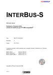


![[December] [2011] Oracle Part Number E51535-01](http://vs1.manualzilla.com/store/data/005639894_1-7cab28abe75641f653b0af59966ce958-150x150.png)