1
Operating Instructions
Universal measuring unit for heavy current variables SINEAX CAM
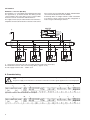
Obligatory safety instructions are marked with the following
symbols in these directions:
2. Scope of supply
SINEAX CAM (1)
1 Safety instructions (2)
1 Software and documentation CD (3)
1 USB cable (4)
1
2
Device may only be disposed of in a professional manner!
Contents
1. Read first and then... ....................................................2
2. Scope of supply ...........................................................2
3. Brief description ...........................................................2
4. Physical installation ......................................................2
4.1 Mounting ................................................................2
4.2 Releasing ................................................................3
5. Electrical connections ..................................................3
5.1 Inputs and outputs .................................................3
5.2 Interface .................................................................5
6. Commissioning.............................................................6
6.1 Software installation ...............................................7
6.2 Parametrization ......................................................7
6.3 Simulation / measurement acquisition ...................7
6.4 Protecting devices ..................................................7
6.5 MODBUS ................................................................7
6.6 Graphic display (optional).......................................7
6.7 Modbus/TCP ..........................................................8
6.8 IEC 61850 ...............................................................8
7. Technical data ..............................................................8
7.1 Measurement input ................................................8
7.2 I/O-Interface .........................................................10
7.3 Interface ...............................................................10
7.4 Further information ...............................................10
7.5 Logger and lists (optional) ....................................11
8. Maintenance ...............................................................12
9. Dimensional drawings ................................................12
10. Safety notes ...............................................................12
11. Declaration of conformity ...........................................12
1. Read first and then …
Perfect and safe operation requires that Operating Instructions has been read and understood!
This device should only be handled by staff
members who are familiar with it and authorised
to work on electric facilities.
The device must be closed down if safe operation is not
possible any more (e.g. visible damage). All connections
are to be switched off. The device must be returned to our
plant or to a service centre authorised by us.
An intervention in the device cancels any warranty
claim!
2
4
3
3. Brief description
SINEAX CAM is designed for measurements in electric
distribution systems or in industrial facilities. Along with the
current system state the pollution due to non-linear loads as
well as the overall load of the supply system can be detected.
Consistent measurement also guarantees that every network
change is reliably acquired and included in measured date.
The high-performance measuring system makes the device
also suitable for strong distorted systems as well as for zero
crossing or phase-angle controls.
The I/O interface may be individually assorted depending on
the application. Up to 4 modules with different functionality
may be used.
The logger allows long-term recordings of measurement
progressions, e.g. to monitor the variable load of transformers, as well as meter readings at definable times. Lists
offer the chronological recording of events, alarms or system
messages for further analysis of occurrences in the power
system.
The graphic display is intended for on-site visualization of
measurements, lists and alarms. Via keypad the user can
e.g. acknowledge alarms or reset extreme values.
4. Physical installation
4.1 Mounting
The device is mounted on a top-hat rail.
Please ensure tha the operating temperature limits
are not exceeded when determining the place
of mounting (place of measurement):
– 10 … 55 °C