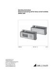
1
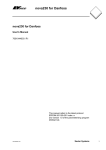
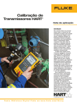
®
HART Transmitter
Calibration
Application Note
Introduction
In today’s process plants, most
new field instruments are smart
digital instruments. Smart implies a microprocessor-based
instrument with extra functionality and digital compensation,
supporting multiple sensor types
or multiple variables. These instruments generally offer better
accuracy, long-term stability,
and reliability than conventional
analog instruments.
The most common class of
smart instruments incorporates
the HART protocol, with more
than five million HART instruments in use in 100,000 plants
worldwide. HART, an acronym
for Highway Addressable Remote
Transducer, is an industry standard that defines the communications protocol between smart
field devices and a control system that employs traditional
4-20 mA wiring.
Two capabilities are required
to properly service HART instruments: precision analog source
and measure capability and digital communication capability.
Until recently, this required two
separate tools, a calibrator and a
communicator. Today, the capabilities of those two tools are
available in a single HART Documenting Process Calibrator that
can help you quickly and effectively service HART instruments.
HART calibration
is required!
A common misconception is
that the accuracy and stability
of HART instruments eliminate
the need for calibration.
Another misconception is that
calibration can be accomplished
by re-ranging field instruments
using only a HART communicator. Still another misconception
is that the control system can
remotely calibrate smart instruments. These are not true. All
instruments drift. Re-ranging
with just a communicator is not
calibration. A precision calibrator or standard is required.
Regular performance verification with a calibrator traceable
to national standards is necessary due to:
1. Shifts in performance of
electronic instruments over
time, due to exposure of the
electronics and the primary
sensing element to temperature, humidity, pollutants,
vibration, and other field
environmental factors.
2. Regulations governing occupational safety, consumer
safety, and environmental
protection.
3. Quality programs such as
ISO 9000 standards for all
instruments that impact
product quality.
4. Commercial requirements
such as weights, measures,
and custody transfer.
Analog
Input
Sensor
Input
Section
Sensor Trim
Figure 1
2 Fluke Corporation
Hart Transmitter Calibration
Regular calibration is also prudent since performance checks
will often uncover problems not
directly caused by the instrumentation, such as solidified or
congealed pressure lines, installation of an incorrect thermocouple type, or other errors
and faults.
A calibration procedure consists of a verification (As Found)
test, adjustment to within acceptable tolerance if necessary,
and a final verification (As Left)
test if an adjustment has been
made. Data from the calibration
are collected and used to complete a report of calibration,
documenting instrument performance over time.
All instruments, even HART
instruments, must be calibrated
on a regular, preventive maintenance schedule. The calibration interval should be set short
enough to insure that an instrument never drifts out of
tolerance, yet long enough to
avoid unnecessary calibrations.
Alternatively, the interval may
be determined by critical process requirements, e.g., calibration before each batch.
PV
(digital
input)
Conversion
Section
PVAO
(digital
4-20 mA)
LRV/URV Adjust
How are HART
instruments properly
calibrated?
To calibrate a HART instrument
consistent with its application, it
is very helpful to understand the
functional structure of a typical
HART transmitter. The article in
Appendix A, by Kenneth L.
Holladay of Southwest Research
Institute, describes a typical
HART instrument and defines
both proper and improper calibration practices. Originally
published in Intech, May 1996, it
is reprinted with permission of
the author.
Note: If you are unfamiliar with HART
calibration or need a review, this is an
excellent point to stop and read the article
in Appendix A. It covers the basics of HART
instrumentation and addresses issues critical
to instrument maintenance.
HART instruments consist of
three distinct sections (see
Figure 1). Proper HART calibration may involve either or both
sensor trim and output trim.
Adjusting range values (LRV and
URV) without a calibrator is not
calibration. Performing an output
trim while ignoring the input
section is not proper calibration.
Adjusting range values with a
calibrator may be a practical
calibration alternative for instruments operated in 4-20 mA
analog mode, provided that the
PV and PVAO are not used for
process control.
Output 4-20 mA
Section
Output Trim
Analog
mA Output
Analog Measure Value
Model Number
Analog Source Value
PV
(Primary Variable)
Tag ID
PVAO
(Digital representation
of the Primary Variable
Analog Output)
PV LRV
(Primary Variable
Lower Range Value)
PV URV
(Primary Variable
Upper Range Value)
Figure 2
New tool speeds
calibration
Today, instrument maintenance
is moving out of the shop and
into the field. This reduces process interruptions and avoids
the time and expense of returning instruments to the shop.
Portable communicators and
calibrators are often used to-
3 Fluke Corporation
gether to complete field calibrations. However, the desire to
carry less equipment and to
perform maintenance in the
field has created a need for a
new class of calibration tool.
The new 744 Documenting
Process Calibrator from Fluke is
the first powerful yet easy-touse tool for field calibration of
HART instrumentation. Pressing
Hart Transmitter Calibration
a single key enters the HART
mode and displays the essential
HART information in the Active
Device Screen, shown in Figure
2. Additional HART functionality
is accessed with only a few
more keystrokes, per the menu
tree in Figure 3.
• View process
variables
Process
Basic
• View variable
map
• Re-map process
variables
(Dual sensor
temperature
devices)
Detailed
(coriolis)
• Keypad input
• Adjust URV, LRV to
applied values
• Tag
• PV units
• LRV, URV
• Damping
• Transfer function
Sensor 1
• Sensor serial number
• Sensor lower and
upper limits
• Sensor minimum span
Temperature
devices only:
• Change Sensor Type
• Change Sensor
Connections
• Config Sensor
• Config Output
Sensor
Device
Identification
Setup
• Software Version
• Final assembly number
• LRV, URV
• Damping
• Transfer function
HART
Output
Loop test
Service
Pressure
zero trim
HART
Information
Output trim
Abort
Sensor trim
Sensor 2
• Change Sensor Type
• Change Sensor
Connections
(Dual sensor
temperature devices)
• Dual Sensor Config
(Dual sensor
temperature devices)
• Manufacturer
• Model
• Device HART ID
• Software revision
• Hardware revision
• Number of preambles
• Write protect
• Alarm state
• HART poll address
• HART burst mode
• HART burst command
Figure 3
4 Fluke Corporation
No communicator is
required!
• Interrogate HART devices to
• Read and write HART tag and
The 744 requires no external
box or communicator for everyday HART calibration and maintenance. It supports many
popular models of HART transmitters, with more devicespecific command support than
any other HART field calibrator.
•
•
Hart Transmitter Calibration
•
determine type, manufacturer,
model, tag-ID, PV, and PVAO
Perform automated HART
sensor trim and output trim
for selected devices
Adjust ranging, damping, and
other basic process–configuration settings
message fields to re-label
smart transmitters
Clone additional transmitters
with basic HART configuration
data
Versatile HART protocol
support
HART operating modes
supported
The 744 supports the commands
contained in HART protocol version 5.7. With 2 MB of memory,
the 744 supports a substantial
set of HART instructions:
• Universal commands —
provide functions that are
implemented in all field
devices, for example, read
manufacturer and device
type, read primary variable
(PV), or read current output
and percent of span
• Common practice commands — provide functions
that are common to many but
not all field devices, for
example read multiple variables, set damping time, or
perform loop test
• Device-specific commands —
provide functions that are
unique to a particular field
device, for example sensor
trim. The 744 Version 2.5
supports these devices:
• For Point to Point operation,
the most commonly used
mode, connects the 744 to a
single HART device in a 4-20
mA loop.
• In Multi-Drop mode, several
HART instruments can be
bussed together. The 744
searches for each, identifies
addresses in use, and allows
you to select the instrument
for calibration and related
operations.
• In Burst Mode, the HART
instrument transmits bursts of
data without waiting to be
interrogated by a master unit.
The 744 can take transmitters
out of burst mode during test
or calibration, then later
restore them to burst mode.
Is there still a role for the
communicator?
Commissioning a HART instrument or modifying HART variables not supported by the 744
requires the use of a communicator. The 744 is designed to
Manufacturer
Pressure Instruments Temperature Instruments
ABB/Kent-Taylor
600T
658T1
1
ABB/
Contrans P,
Hartmann & Braun
AS 800 Series
Endress & Hauser
CERABAR S,
TMT 1221, TMT 1821,
CERABAR M,
TMT 1621
DELTABAR S
Foxboro Eckardt
TI/RTT201
Foxboro/Invensys
I/A Pressure
Fuji
FCX
FRC
FCXAZ
Honeywell
ST3000
STT25T1, STT25H1
Micro Motion
Moore Products
Rosemount
Siemens
SMAR
Viatran
Wika
Yokogawa
1151
2088
3001C
3051, 3051S
SITRANS P DS
SITRANS P ES
LD301
I/A Pressure
UNITRANS
EJA
HART calibration
applications
The following examples demonstrate how the 744 makes HART
calibration an efficient operation. The 744 enables easy
hookup using its HART cable,
fast access to the most important HART data, automatic
branching to appropriate adjustment choices, automatic
completion of test templates,
and automatic fetching and
sending of analog readings
during trim.
Coriolis Instruments
2000
2000 IS
9701
9712
9739
3441
3044C
644
3144
3244, 3144P
TT3011
T32H1
YTA 110, 310 and 320
1
Table 1
5 Fluke Corporation
perform the vast majority of
day-to-day operations you normally perform with a separate
communicator. The HART capability of the 744 is comparable
to that of the model 275 HART
communicator, with the exception of the DD interpreter. While
the DD interpreter enables the
275 communicator to read command set libraries from any
HART supplier, it offers capabilities far beyond those generally
required for daily HART instrument maintenance.
Hart Transmitter Calibration
Sensor Trim not supported
Example 1
Calibration of a
Rosemount 3051 HART
Pressure Transmitter
Basic connections
This example assumes that the
transmitter is isolated from the
process and is not electrically
connected to a loop power supply. Make basic connections to
the 3051 per the diagram in
Figure 4. Polarity of the HART
communication connection is
not important. A separate
250 ohm resistor is not necessary because the 744 incorporates a resistor in series with
the 24V loop supply through its
mA jacks. The 3051 in this example is configured for psi units.
Procedure
1. Power on the Fluke 744
Calibrator. Press the red
key followed by the Loop
Power softkey and the 744
will display the basic HART
information for the 3051
(Figure 5).
key again and
2. Press the
you are prompted to select
the 744 configuration (Figure
6). Selecting MEAS mA,
SOURCE psi will configure
the calibrator to measure the
analog mA output and the
pressure being applied simultaneously to the transmitter input and the pressure
module. (Selecting MEAS PV,
SOURCE psi will configure
the 744 to evaluate the digital PV output from the transmitter.) Press
to select.
ENTER
Figure 5
Figure 6
HART Connection
Hand Pump
744
DOCUMENTING PROCESS CALIBRATOR
S I G N A L
+
–
T E S T
MEAS
SOURCE
V
RTD
mA
V
Hz
V
TC
RTD
7
8
9
4
5
6
1
2
3
0
.
mA
SETUP
Pressure
Module
CLEAR
( ZERO)
ENTER
mA
Pressure Input
V
RTD
CAT
30V
MAX
SOURCE
MEAS
30V
MAX
30V
MAX
300V
MAX
TC
Red
mA Measure, 24V Loop
Figure 4
6 Fluke Corporation
Hart Transmitter Calibration
Black
5. If the As Found test failed
7. Select Output Trim and
3. Vent the pressure line and
. The value of the
(i.e., there were highlighted
press
press
to zero the pressure
primary variable (PVAO) is in
errors in the error summary
module. Press the As Found
the upper right corner of the
table), adjustment is necessoftkey, and then press
display. This is normally a
sary. Press the Adjust
to select Instrument for a
4 mA signal. The mA value,
softkey. Select Sensor Trim
linear transmitter calibration.
as constantly measured by
and press
. (Do not select
(If the 3051 is configured for
the Fluke 744, is in the cenPressure Zero Trim. It is the
square root output, select
ter of the display. Press the
same as trimming the lower
Instrument.) Notice that
Fetch softkey to load the
sensor point at zero, which is
the calibration template is
measured mA value. Press
useful for pressure transmitautomatically completed with
Send to send the value to
ters that do not offer Sensor
the exception of Tolerance.
the 3051 to trim the output
Trim.) The 744 screen should
Fill in the appropriate test
section for the 4 mA value.
look like Figure 8.
tolerance and press Done.
Press Continue for the 20
4. Press the Manual Test
mA trim and repeat this step.
softkey to begin calibration.
8. After completing Output Trim,
Apply the input pressures as
press the Done softkey and
instructed in the SOURCE
proceed with the As Left
screen. Press the Accept
verification test. Press the As
Point softkey when the corLeft softkey. Press Done and
rect pressure is applied for
then press Manual Test.
each point. When the test is
Apply the requested prescomplete, the error summary
sures and press Accept Point
table is displayed (Figure 7).
when the readings are
Test errors exceeding the
stable. On completion an
tolerance are highlighted.
error summary table is disWhen done viewing the
Figure 8
played. If none of the errors
table, press the Done softkey.
are highlighted (Figure 9),
Press Done again to accept,
6. Select Perform user trim –
the 3051 passes the calibraor
to change the tag,
both and press
. Zero the
tion test. If errors are highserial number or ID fields.
pressure module (vented to
lighted, the test has failed
atmosphere) by pressing
.
and further adjustment is
Press the Continue softkey
required. Return to step 5 for
and you are prompted for the
adjustment of the 3051.
Lower Trim value. For best
results, apply the LRV pressure and press Fetch to load
the value being measured by
the pressure module. Press
Trim. Then press Continue
to move to the Upper Trim.
As before, apply the URV
pressure, press Fetch, and
press Trim. If the 3051 is
used with the digital PV
Figure 7
output, skip to step 8 and
perform the As Left test. If
the 4-20 mA analog output
is used in the process, conFigure 9
tinue on to step 7.
CLEAR
ENTER
(ZERO)
ENTER
ENTER
ENTER
ENTER
CLEAR
(ZERO)
7 Fluke Corporation
Hart Transmitter Calibration
Example 2
Calibration of a
Rosemount 3144 HART
Temperature Transmitter
Basic connections
This example assumes that the
transmitter is isolated from the
process and is not electrically
connected to a loop power
supply. Make basic connections
to the 3144 per the diagram in
Figure 10. Polarity of the HART
communication connection is
not important. A separate
250 ohm resistor is not necessary because the 744 incorporates a resistor in series with
the 24V loop supply through its
mA jacks. The 3144 in this example is configured for a type K
thermocouple sensor with a
span of 0-300 °C.
Procedure
1. Power on the Fluke 744
Calibrator. Press the red
key followed by the Loop
to
Power softkey. Press
bypass the warning screens
and the 744 will display the
basic HART information for
the 3144 (Figure 11).
ENTER
2. Press the
key again and
you are prompted to select
the 744 configuration (Figure 12). Selecting MEAS mA,
SOURCE T/C typ K configures the calibrator to measure the analog mA output of
the transmitter and source
the correct temperature
stimulus at the 3144 input.
(Selecting MEAS PV,
SOURCE T/C typ K will
configure the 744 to evaluate the digital PV output
from the transmitter.) Press
to select.
ENTER
Figure 11
HART Connection
TC
+
744
DOCUMENTING PROCESS CALIBRATOR
2
1
TC
–
3
4
–
5
+
T
3144
Transmitter
MEAS
SOURCE
mA
V
Hz
V
TC
RTD
7
8
9
4
5
6
1
2
3
0
.
V
RTD
mA
SETUP
CLEAR
(ZERO)
ENTER
mA
V
+
RTD
Red
CAT
30V
MAX
SOURCE
MEAS
30V
MAX
30V
MAX
300V
MAX
TC
–
Black
Figure 10
8 Fluke Corporation
Hart Transmitter Calibration
5. If the As Found test failed
(i.e., there were highlighted
errors in the error summary
table), adjustment is necessary. Press the Adjust softkey.
Select Sensor Trim and
press
. Select Perform
user trim – both and press
. The 744 screen should
look like Figure 14.
ENTER
ENTER
Figure 12
Figure 15
3. Press the As Found softkey,
8. After completing Output Trim,
to select
and then press
press the Done softkey and
Instrument for a linear
proceed with the As Left
transmitter calibration. Notice
verification test. Press the As
that the calibration template
Left softkey. Press Done and
is automatically completed
then press Auto Test. On
with the exception of the
completion, an error summary
Tolerance. Fill in the approtable is displayed. If errors
priate test tolerance and
are highlighted, the test has
Figure 14
press the Done softkey.
failed and further adjustment
is required. Return to step 5
4. Press the Auto Test softkey
6. For best results, press LRV to
for adjustment of the 3144.
to begin calibration. Once
apply the LRV for the Lower
the test is complete, an error
Trim value. Press Trim and
summary table is displayed
then Continue to move to
(Figure 13). Test errors exthe Upper Trim. Press URV,
ceeding the tolerance are
press Trim, and then press
highlighted. When done
Done. If the 3144 is used
viewing the table, press the
with the digital PV output,
Done softkey. Press Done
skip to step 8 and perform
again to accept, or
to
the As Left test. If the analog
change the tag, serial num4-20 mA output is used in
ber or ID fields.
the process, continue on to
step 7.
7. Select Output Trim and
press
. The value of the
Figure 16
primary variable (PVAO) is in
the upper right corner of the
display. (Figure 18). This is
normally a 4 mA signal. The
mA value, as constantly
measured by the Fluke 744,
is in the center of the display. Press the Fetch softkey
to load the measured mA
Figure 13
value. Press Send to send
the value to the 3144 to trim
the output section for the 4
mA value. Press Continue for
the 20 mA trim and repeat
this step.
ENTER
ENTER
ENTER
9 Fluke Corporation
Hart Transmitter Calibration
Example 3
Calibration of HART
instruments using
universal commands
The 744 supports a majority of
the installed workload of HART
transmitters – see Table 1 – by
supporting sensor trim, which
employs device-specific commands that are unique to a particular instrument. So how can
you calibrate instruments that
are not supported by the 744?
The short answer is that the
744 supports a substantial set of
the universal HART commands
and the common practice HART
commands. The 744 can communicate with virtually any
HART instrument and, in most
cases, can complete a calibration
procedure (except for sensor trim
for unsupported instruments).
This example applies to
instruments used in analog
mode (4-20 mA). If the instrument is operated in digital
mode, i.e., its PV is the output
variable that is used for control,
a calibration of the Input Section
is all that is needed. Adjustment
will require a Sensor Trim, (see
Figure 17) which means that for
instruments not supported by the
744 you will need to use both a
744 (to perform the As Found
and As Left tests and record the
results) and a communicator (to
perform sensor trim).
For instruments used in analog mode, i.e., where the 4-20
mA analog output is used for
control, the 744 can be used for
calibration. After performing an
As Found and determining that
Analog
Input
Sensor
Input
Section
Sensor Trim
Figure 17
10 Fluke Corporation
Hart Transmitter Calibration
adjustment is required, this
example first performs an Output
Trim to bring the instrument
within tolerance. Failing that,
the example performs an adjustment to the Lower and Upper
Range Values (LRV and URV) to
compensate for input section
error.
Note: Appendix A explains that these adjustments do not constitute a proper HART calibration. While this is true, these adjustments
are a practical calibration alternative for
instruments operated in 4-20 mA analog
mode if error corrections are not large
How to determine digital
or analog?
The transmitter is in digital
mode if its HART Poll Address is
set between 1 to 15. An address
of 0 (zero) sets it to 4-20 mA
analog output mode. The 744
will automatically connect to a
device at address 0; if a device
744
mA
V
Hz
8
9
4
5
6
1
2
3
0
.
mA
SETUP
TC
RTD
7
V
RTD
Basic connections
This example assumes that the
transmitter is isolated from the
process and is not electrically
connected to a loop power supply. Make basic connections to
the transmitter per the diagram
in Figure 18. Polarity of the
HART communication connection is not important. A separate 250 ohm resistor is not
necessary because the 744
incorporates a resistor in series
with the 24V loop supply
through its mA jacks. This example assumes a type K thermocouple transmitter with an
input range of 0-100 °C, 4-20
mA output, and a 0.25% test
tolerance.
DOCUMENTING PROCESS CALIBRATOR
MEAS
SOURCE
V
is not found at 0 the 744 will
begin polling addresses 1 to 15.
The 744 also displays a nonzero address with the basic
HART information.
TEST DC PWR
CLEAR
– ++ –
( ZERO)
ENTER
mA
Red
V
RTD
CAT
30V
MAX
SOURCE
MEAS
30V
MAX
30V
MAX
300V
MAX
TC
Black
Figure 18
PV
(digital
input)
Conversion
Section
PVAO
(digital
4-20 mA)
LRV/URV Adjust
Output 4-20 mA
Section
Output Trim
Analog
mA Output
3. Press the As Found softkey
Procedure
and press
to select
1. Power on the Fluke 744
Instrument calibration. Move
Calibrator. Press the
key
the cursor to Tolerance and
and the Loop Power softkey
ENTER the appropriate test
(if loop power is not already
tolerance (0.25% in this exsupplied). Press
until any
ample). Verify that the 0%
device warnings are cleared
Value and 100% Value are
and the basic HART informathe proper, nominal operattion is displayed (Figure 19).
ing values for the transmitter
(0.0 °C and 100.0 °C in this
example, Figure 21). If the
Lower (0%) and Upper
Figure 22
(100%) Range Values (LRV
If errors are highlighted,
and URV) have been previadjustment is necessary by
ously modified for calibration
performing an Output Trim.
purposes, you will need to
Press Done to leave the reENTER the nominal values.
sults screen, edit the tag,
For example, if a previous
serial number or ID fields as
calibration modified the URV
necessary, and press Done
to 100.2 °C, you need to
again.
manually ENTER the nominal value of 100.0 °C for the 5. Press the Adjust softkey,
Figure 19
100% Value. Entering nomiselect Output Trim and press
nal zero and span values
. The value of the primary
2. Press the
key again and
ensures that errors are calcuvariable (PVAO) is in the
you are prompted to select
lated correctly.
upper right corner of the
the 744 configuration (Figure
display (Figure 23). This is
20). Move the cursor to
normally a 4 mA signal. The
MEAS mA, SOURCE T/C
real-time mA value as meatyp K, and press
. (If you
sured by the Fluke 744, is in
were verifying the digital PV
the center of the display.
instead of the mA output, i.e.,
Press the Fetch softkey to
the transmitter has a nonload the measured mA value.
zero HART poll address, you
Press the Send softkey to
would select MEAS PV,
send the value to the transSOURCE T/C typ K instead.)
mitter to trim the output
section for the 4 mA value.
Press Continue for the 20
mA adjustment and repeat
Figure 21
this step.
ENTER
ENTER
ENTER
ENTER
Figure 20
4. Press Done and then press
Auto Test. Once the test is
complete, an error summary
table is displayed (Figure 22).
Test errors exceeding the
tolerance are highlighted. If
the test passed, i.e., if no
errors are highlighted, adjustment is not required.
Figure 23
11 Fluke Corporation
Hart Transmitter Calibration
6. Now perform an As Left test. 9. Calculate the new LRV or
Press As Left, press Done,
URV by multiplying the span
and then press Auto Test. On
by the error in percent and
completion the error sumadding that to the old value.
mary table is displayed. If
If our example has the folerrors are highlighted, the
lowing nominal Source valtest has failed and further
ues, errors, and old LRV and
adjustment is required.
URV values:
Note: If the failure error is large, sensor trim
adjustment with a communicator may be necessary. Often, however, adjustment can be accomplished with a 744 by modifying the LRV
(Lower Range Value) and URV (Upper Range
Value) to compensate for Input Section error.
0% Value
Source
Error%
Old LRV/
URV
0.0 ºC
0.84%
0.4 ºC
-2.41%
102.0 ºC
100%Value 100.0 ºC
Table 2
Figure 24
7. In the case of a pressure
11. Now press Done and then
transmitter that has onpress Abort 3 times. PerCalculate the new LRV and
board Zero and Span adjustform a new As Found test
URV as follows:
ment buttons, calibration is
by pressing As Found. (ReLRVnew = LRVold + (Span × Error0%)
easy. Simply apply a calimember to make sure that
brated source at the LRV and
the original, nominal zero
LRVnew = 0.4 ºC + (100.0 ºC × 0.84%)
URV values and press the
and span values are shown
LRVnew = 0.4 ºC + (100.0 ºC × 0.0084)
respective Zero and Span
as the 0% Value and 100%
buttons on the transmitter.
LRVnew = 0.4 ºC + 0.8 ºC
Value.) Press Done and
Then verify the condition of
then press Auto Test. On
LRVnew = 1.2 ºC
the transmitter by completcompletion, the error suming an As Left test as in step
mary table is displayed.
URVnew = URVold + (Span × Error100%)
6. Many HART transmitters
If errors are highlighted,
do not have physical adjustURVnew = 102.0 ºC + (100.0 ºC ×
the test has failed – repeat
ments and need either a
–2.41%)
the adjustment or trim
communicator or a Fluke 744
sensor section with a
URVnew = 102.0 ºC + (100.0 ºC ×
to adjust the LRV and URV
communicator.
–0.0241)
values. For those cases, proNote: If you encounter any difficulty with
URVnew = 102.0 ºC – 2.4 ºC
ceed to step 8.
any of these examples, you may call 1-800URV
=
99.6
ºC
44-FLUKE for assistance (1-800-443-5853).
8. The error summary table
new
(displayed from step 6) provides the data necessary to
and then press the
make LRV and URV changes. 10. Press
Setup softkey. Select Basic
Write down the ERROR %
from the menu and press
values for the failed 0% and
to display the basic setup
100% test points. (If the error
parameters shown in Figure
summary table is no longer
24. To ENTER the new LRV,
displayed, you can use the
move the cursor to Lower
Review Memory softkey to
Range Value and press
.
recall the As Left data.)
Type
the
new
LRV
and
press
Return the 744 to the normal
. Also type in the new
Measure/Source screen disURV
and press
. Press the
playing the As Left softkey
Send softkey.
by pressing the Done softkey
3 times.
ENTER
ENTER
ENTER
ENTER
12 Fluke Corporation
Hart Transmitter Calibration
a physical quantity into an elec- variable using a communicator,
trical signal. However, the simi- this is the value that you see.
The second box is strictly a
larity ends there. Instead of a
mathematical conversion from
purely mechanical or electrical
Calibrating HART
path between the input and the the process variable to the
Transmitters
resulting 4-20 mA output signal, equivalent milliamp representaBy Kenneth L. Holladay, P.E.
a HART transmitter has a micro- tion. The range values of the
instrument (related to the zero
processor that manipulates the
Calibrating a conventional
and span values) are used in
input data. As shown in Figure
instrument
conjunction with the transfer
A2, there are typically three
For a conventional 4-20 mA
function to calculate this value.
calculation sections involved,
instrument, a multiple point test and each of these sections may Although a linear transfer functhat stimulates the input and
tion is the most common, presbe individually tested and
measures the output is sufficient adjusted.
sure transmitters often have a
to characterize the overall accuJust prior to the first box, the square root option. Other special
racy of the transmitter. The
instruments may implement
instrument’s microprocessor
normal calibration adjustment
measures some electrical prop- common mathematical transforinvolves setting only the zero
erty that is affected by the pro- mations or user defined break
value and the span value, since cess variable of interest. The
point tables. The output of the
there is effectively only one
second block is a digital repremeasured value may be milliadjustable operation between
sentation of the desired instruvolts, capacitance, reluctance,
the input and output as illusinductance, frequency, or some ment output. When you read the
trated below.
other property. However, before loop current using a communiit can be used by the micropro- cator, this is the value that you
see. Many HART instruments
cessor, it must be transformed
Zero and Span
support a command which puts
to a digital count by an analog
Adjustments
the instrument into a fixed outto digital (A/D) converter.
In the first box, the micropro- put test mode. This overrides the
Sensing
4-20 mA
cessor must rely upon some form normal output of the second
Element
Output
Analog
of equation or table to relate the block and substitutes a specified
Electronics
raw count value of the electrical output value.
The third box is the output
measurement to the actual propFigure A1
erty (PV) of interest such as tem- section where the calculated
Conventional Transmitter Block Diagram
perature, pressure, or flow. The output value is converted to a
count value that can be loaded
principle form of this table is
This procedure is often reinto a digital to analog conusually established by the
ferred to as a Zero and Span
verter. This produces the actual
manufacturer, but most HART
Calibration. If the relationship
instruments include commands analog electrical signal. Once
between the input and output
again the microprocessor must
to perform field adjustments.
range of the instrument is not
rely on some internal calibration
linear, then you must know the This is often referred to as a
factors to get the output correct.
transfer function before you can sensor trim. The output of the
first box is a digital representa- Adjusting these factors is often
calculate expected outputs for
referred to as a current loop trim
tion of the process variable.
each input value. Without
or 4-20 mA trim.
When you read the process
knowing the expected output
values, you cannot calculate the
performance errors.
Range and
High and Low
High and Low
Appendix A
PV
Counts
Input
Section
13 Fluke Corporation
PV
Conversion
Section
PV may be
read digitally
Figure A2
HART Transmitter Block Diagram
Hart Transmitter Calibration
mA
Output Trim
D/A
Counts
Counts
A/D
Counts
mA
For a HART instrument, a multiple point test between input
and output does not provide an
accurate representation of the
transmitter’s operation. Just like
a conventional transmitter, the
measurement process begins
with a technology that converts
Transfer Function
Sensor Trim
PV
Calibrating a HART
instrument
mA
Output
Section
mA may be set
and read digitally
HART calibration
requirements
Based on this analysis, you can
see why a proper calibration
procedure for a HART instrument is significantly different
than for a conventional instrument. The specific calibration
requirements depend upon the
application.
If the application uses the
digital representation of the
process variable for monitoring
or control, then the sensor input
section must be explicitly tested
and adjusted. Note that this
reading is completely independent of the milliamp output, and
has nothing to do with the zero
or span settings. The PV as read
via HART communication continues to be accurate even
when it is outside the assigned
output range. For example, a
range 2 Rosemount 3051c has
sensor limits of -250 to +250
inches of water. If you set the
range to 0 - 100 inches of
water, and then apply a pressure of 150 inches of water, the
analog output will saturate at
just above 20 milliamps. However, a communicator can still
read the correct pressure.
If the current loop output is
not used (that is the transmitter
is used as a digital only device),
then the input section calibration is all that is required. If the
application uses the milliamp
output, then the output section
must be explicitly tested and
calibrated. Note that this calibration is independent of the
input section, and again, has
nothing to do with the zero and
span settings.
always a linear relationship
between the input and output,
and both are recorded in the
same engineering units. In general, the desired accuracy for this
test will be the manufacturer’s
accuracy specification.
If the test does not pass, then
follow the manufacturer’s recommended procedure for trimming the input section. This
may be called a sensor trim and
typically involves one or two
trim points. Pressure transmitters also often have a zero trim,
where the input calculation is
adjusted to read exactly zero
(not low range). Do not confuse
a trim with any form of re-ranging or any procedure that involves using zero and span
buttons.
Calibrating the output
section
Again, the same basic multiple
point test and adjust technique
is employed, but with a new
definition for input. To run a test,
use a communicator to put the
transmitter into a fixed current
output mode. The input value for
the test is the mA value that you
instruct the transmitter to produce. The output value is obtained using a calibrator to
measure the resulting current.
This test also implies a linear
relationship between the input
and output, and both are recorded in the same engineering
units (milliamps). The desired
accuracy for this test should also
reflect the manufacturer’s accuracy specification.
If the test does not pass, then
follow the manufacturer’s recommended procedure for trimCalibrating the input section ming the output section. This
may be called a 4-20 mA trim, a
The same basic multiple point
current loop trim, or a D/A trim.
test and adjust technique is
employed, but with a new defi- The trim procedure should require two trim points close to or
nition for output. To run a test,
use a calibrator to measure the just outside of 4 and 20 mA. Do
not confuse this with any form
applied input, but read the
of re-ranging or any procedure
associated output (PV) with a
communicator. Error calculations that involves using zero and
span buttons.
are simpler since there is
14 Fluke Corporation
Hart Transmitter Calibration
Testing overall performance
After calibrating both the Input
and Output sections, a HART
transmitter should operate
correctly. The middle block in
Figure A2 only involves computations. That is why you can
change the range, units, and
transfer function without necessarily affecting the calibration.
Notice also that even if the instrument has an unusual transfer function, it only operates in
the conversion of the input
value to a milliamp output value,
and therefore is not involved in
the testing or calibration of either the input or output sections.
If there is a desire to validate
the overall performance of a
HART transmitter, run a Zero
and Span test just like a conventional instrument. As you
will see in a moment, however,
passing this test does not necessarily indicate that the transmitter is operating correctly.
Effect of damping on test
performance
Many HART instruments support
a parameter called damping. If
this is not set to zero, it can
have an adverse effect on tests
and adjustments. Damping induces a delay between a
change in the instrument input
and the detection of that
change in the digital value for
the instrument input reading
and the corresponding instrument output value. This damping induced delay may exceed
the settling time used in the test
or calibration. The settling time
is the amount of time the test or
calibration waits between setting the input and reading the
resulting output. It is advisable
to adjust the instrument’s
damping value to zero prior to
performing tests or adjustments.
After calibration, be sure to
return the damping constant to
its required value.
Operations that are NOT
proper calibrations
Digital range change
There is a common misconception that changing the range of
a HART instrument by using a
communicator somehow calibrates the instrument. Remember that a true calibration
requires a reference standard,
usually in the form of one or
more pieces of calibration
equipment to provide an input
and measure the resulting output. Therefore, since a range
change does not reference any
external calibration standards, it
is really a configuration change,
not a calibration. Notice that in
the HART transmitter block diagram (Figure 2), changing the
range only affects the second
block. It has no effect on the
digital process variable as read
by a communicator.
Zero and span adjustment
Using only the zero and span
adjustments to calibrate a HART
transmitter (the standard practice associated with conventional transmitters) often
corrupts the internal digital
readings. You may not have
noticed this if you never use a
communicator to read the range
or digital process data. As
shown in Figure 2, there is
more than one output to consider. The digital PV and
milliamp values read by a communicator are also outputs, just
like the analog current loop.
Consider what happens
when using the external zero
and span buttons to adjust a
HART instrument. Suppose that
an instrument technician installs and tests a differential
pressure transmitter that was
set at the factory for a range of
0 to 100 inches of water. Testing the transmitter reveals that
it now has a 1 inch of water
15 Fluke Corporation
zero shift. Thus with both ports
vented (zero), its output is 4.16
mA instead of 4.00 mA, and
when applying 100 inches of
water, the output is 20.16 mA
instead of 20.00 mA. To fix this
he vents both ports and presses
the zero button on the transmitter. The output goes to 4.00
mA, so it appears that the adjustment was successful.
However, if he now checks
the transmitter with a communicator, he will find that the
range is 1 to 101 inches of water, and the PV is 1 inch of
water instead of 0. The zero
and span buttons changed the
range (the second block). This
is the only action that the instrument can take under these
conditions since it does not
know the actual value of the
reference input. Only by using
a digital command which conveys the reference value can
the instrument make the appropriate internal adjustments.
The proper way to correct a
zero shift condition is to use a
zero trim. This adjusts the instrument input block so that the
digital PV agrees with the calibration standard. If you intend
to use the digital process values
for trending, statistical calculations, or maintenance tracking,
then you should disable the
external zero and span buttons
and avoid using them entirely.
Loop current adjustment
Another observed practice
among instrument technicians
is to use a hand-held communicator to adjust the current
loop so that an accurate input
to the instrument agrees with
some display device on the
loop. If you are using a
Rosemount model 268 communicator, this is a “current loop
trim using other scale.” Refer
again to the zero drift example
just before pressing the zero
Hart Transmitter Calibration
button. Suppose there is also a
digital indicator in the loop that
displays 0.0 at 4 mA, and 100.0
at 20 mA. During testing, it read
1.0 with both ports vented, and
it read 101.0 with 100 inches of
water applied. Using the communicator, the technician performs a current loop trim so that
the display reads correctly at 0
and 100, essentially correcting
the output to be 4 and 20 mA
respectively.
While this also appears to be
successful, there is a fundamental problem with this procedure.
To begin with, the communicator will show that the PV still
reads 1 and 101 inches of water
at the test points, and the digital reading of the mA output still
reads 4.16 and 20.16 mA, even
though the actual output is 4
and 20 mA. The calibration
problem in the input section has
been hidden by introducing a
compensating error in the output section, so that neither of
the digital readings agrees with
the calibration standards.
As published in Intech, May 1996 and also in
HART Book 8, July 1998. Reprinted with the
permission of the author.
Documentation of results
The scheduling of calibrations, creation of procedures and documentation of your calibration
results are facilitated by a number of instrumentation management software packages:
DocuMint ™
PRM (Plant Resource
Manager) from Yokogawa
Electric Corporation.
™
OnTimeSupport ™
Fluke DPC/TRACK ™
Meridium
ProCALV
Intools
Ordering Information
FLUKE-744 Documenting Process Calibrator-HART
Includes: TL224 Industrial Test Leads (two sets), AC220
Test Clips (2 sets), TP220 Test Probes (1 set), BP7235
NiMH Battery Pack, BC7217 Battery Charger, serial port
cable, HART communications cable, DPC/TRACK
Sample with free PC communication utility software,
Instruction Manual, HART User’s Manual, NISTtraceable calibration certificate and data, three-year
warranty.
Optional Accessories
Fluke. Keeping your world
up and running.
IT
ANAG E M E NT
YM
S
T
YS
®
R
TI
90
01
ISO 9001
FI
ED
TO M E E T
Hart Transmitter Calibration
IS
O
For more information call:
U.S.A. (800) 443-5853 or Fax (425) 446-5116
Europe/M-East/Africa +1 (31 40) 2 675 200 or
Fax +1 (31 40) 2 675 222
Canada 1-800-36-FLUKE or Fax (905) 890-6866
Other countries +1 (425) 446-5500 or
Fax +1 (425) 446-5116
Web access: http://www.fluke.com
©2004 Fluke Corporation. All rights reserved.
Printed in U.S.A. 12/2004 1262439 A-US-N Rev F
16 Fluke Corporation
EM
Fluke Europe B.V.
PO Box 1186, 5602 BD
Eindhoven, The Netherlands
AL
Fluke Corporation
PO Box 9090, Everett, WA USA 98206
CE
Fluke-700BCW
Fluke-700PTP
Fluke-700TC1
Fluke-700TC2
BE9005
BC7217
BP7217
BP7235
C700
C781
C789
Pressure Modules
Included with each Fluke Pressure
Module: BSP-ISO to NPT Adapter(s)
(except with P29 - P31), Instruction
Sheet, NIST traceable calibration
report and data, one-year warranty.
Bar Code Wand
Pneumatic Test Pump, 360 psi/25 bar
TC Mini-Plug Kit, 9 types
TC Mini-Plug Kit, JKTERS
Battery Eliminator
Battery Charger
NiCd Battery Pack
NiMH Battery Pack
Hard Carrying Case
Soft Carrying Case
Soft Carrying Case
QU
Fluke-700 Pxx