1
GPIO Signals and Registers
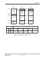
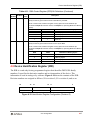
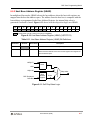
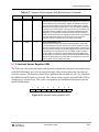
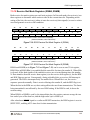
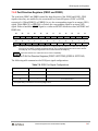
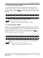
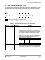
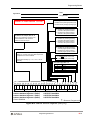
8.7.2 Port E Direction Register (PRRE)
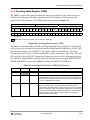
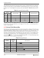
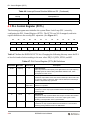
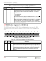
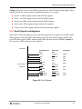
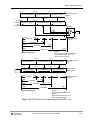
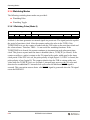
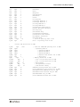
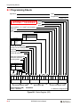
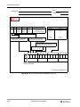
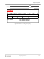
The read/write PRRE controls the direction of SCI GPIO signals. When port signal[i] is
configured as GPIO, PRRE[i] controls the port signal direction. When PRRE[i] is set, the
GPIO port signal[i] is configured as output. When PRRE[i] is cleared, the GPIO port signal[i]
is configured as input. A hardware RESET signal or a software RESET instruction clears all
PRRE bits.
23
22
21
20
19
18
17
16
15
14
13
12
11
10
9
8
7
6
5
4
3
2
1
0
PRRE2
PRRE1
PRRE0
Note:
For bits 2–0, a 0 configures PEn as a GPI and a 1 configures PEn as a GPO. For the SCI, the GPIO signals
are PE[2–0]. The corresponding direction bits for Port E GPIOs are PRRE[2–0].
= Reserved. Read as zero. Write with zero for future compatibility.
Figure 8-9. Port E Direction Register (PRRE X:$FFFF9E)
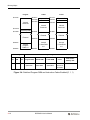
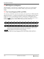
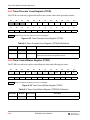
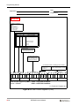
8.7.3 Port E Data Register (PDRE)
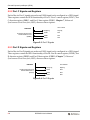
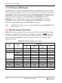
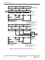
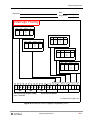
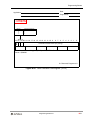
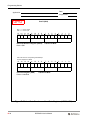
Bits 2–0 of the read/write 24-bit PDRE writes data to or reads data from the associated SCI
signal lines when configured as GPIO signals. If a port signal PE[i] is configured as an input
(GPI), the corresponding PDRE[i] bit reflects the value present on the input signal line. If a
port signal PE[i] is configured as an output (GPO), a value written to the corresponding
PDRE[i] bit is reflected as a value on the output signal line. Either a hardware RESET signal
or a software RESET instruction clears all PDR bits.
23
22
21
20
19
18
17
16
15
11
10
9
8
7
6
5
4
3
Note:
14
13
12
2
1
0
PDRE2
PDRE1
PDRE0
For bits 2–0, the value represents the level that is written to or read from the associated signal line if enabled
as a GPIO signal by the PCRE bits. For SCI, the GPIO signals are PE[2–0]. The corresponding data bits are
PDRE[2–0].
= Reserved. Read as zero. Write with zero for future compatibility.
Figure 8-10. Port Data Registers (PDRE X:$FFFF9D)
Serial Communication Interface (SCI)
8-25