1
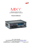
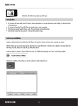
MWS
The Audio Mixer from Switzerland
User Manual
Ab Seriennummer MI0210131
Eb P R Om o t i o n , E r i c h B r ö n n i m a n n , C i t é R o b i n s o n 1 0 , 2 0 7 4 M a r i n , S w i t z e r l a n d
Tel +41 (0)32 763 05 63, Fax +41 (0)32 763 05 64
http :\\:www.ebpromotion.ch, E-mail : [email protected]
Bedienungs-Anleitung Mystère
Januar 2002
Dear Customer,
Let us not waist time with long introduction. The mixer allows you to work with it, without
having to study this manual.
The following points need to be respected:
• The two cover plates over the HF-Docking Bays must always be fixed on to
the mixer before turning it on. They protect the golden contacts underneath
and avoid short circuits. These HF Docking Bays are prepared for easy
installation of the adapters for HF transmitters and receivers should they be
bought at a later date.
• When opening the cover plate of the mixer, make sure nothing drops into the
mixer. Damage to the circuitry or mechanics, caused by such objects may not
be repaired under guarantee.
• Modifications of the mixer, be it mechanically or electronically shall only be
executed by authorised distributors or the manufacturer. Every intervention,
executed by non-authorised people or companies may cancel all guarantee.
Well, if you've got the time…..the short description of the mixer starts on the following page.
Tests, realised with different people, have shown that the eight pages can be read before
fatigue has a chance to overcome you.
PROmotion, Cité Robinson10 2074 Marin, Schweiz www.ebpromotion.ch
Tel +41(0)32 763 05 63 Fax +41 (0)32 763 05 64 e-mail: erich@ebpromotion
eb
1
Bedienungs-Anleitung Mystère
Januar 2002
Front panel
7
6
12
4
8
1
9
5
2
3
10
11
1. 4 Control knobs for channel - level
Switches on the control-panel allow to link electronically channel 1 and 2 as well as
channel 3 and 4. This allows a one-knob control of two channels.
2. 2 Control knobs (red) for the output - level
Both output channels can be linked for one – knob control by a switch on the controlpanel. It is possible to bypass these controls by selecting "CAL" on the switch aside the
knobs for a calibrated output at +6dBu.
3. 4 Gain - control knobs for microphone and line input
When Setting the gain control it is important to observe the overload indicators. Increase
the gain until the LED lights up, then reduce it till the LED turns out. Hoe much you have
to reduce the gain depends on the level of the signal you will have to amplify. Be aware
that a distortion on the input amplification can not be corrected by the output-limiter.
4. „LEVEL“
Level control for the headphone
5. Monitoring switch
Select Stereo, Mono, Left, Right or MS (for the headphone out put only)
6. „BATT“
Push-button for battery-level-control. While pressing the button, the upper row of LED
indicates the charging status of the battery. With fully charged battery all LEDs
illuminate. Every diode less signifies a drop of 0,2V battery tension. The 0 on the scale
above the display corresponds to nominal battery tension providing the setting of the
mixer has been done correctly. (See page 10)
When using a V-mount (or similar) adapter for lock-on batteries with information about
remaining capacity, the mixer can use this information for its display. (e.g. IDX Endura)
PROmotion, Cité Robinson10 2074 Marin, Schweiz www.ebpromotion.ch
Tel +41(0)32 763 05 63 Fax +41 (0)32 763 05 64 e-mail: erich@ebpromotion
eb
2
Bedienungs-Anleitung Mystère
Januar 2002
7. „ON“
On/Off indicator
8. „REF“
Reference-tone switch with three positions
Left position (fix) =
continuous tone of 1 kHz
Right position (momentary) = 1 kHz tone as long as maintained in position
Middle position =
Off
An internal Dip-Switch allows to select between different ballistics and display modes.
(See pages 8 and 10).
9. OUT / RET
Switch for return monitoring. An internal jumper allows to select between two different
display-modes:
• Whether the outgoing or the return signal is monitored, the display always shows the
outgoing signal.
• The display follows the monitoring-switch. In that case, the modulation of the return
signal will be displayed in return-mode.
The standard setting on delivery is always on the outgoing signal unless otherwise
specified by the customer.
10. UNCAL CAL
Selector for calibrated output level (bypasses the master potentiometer; see point 2)
CAL = + 6dB (corresponds to position „0“ of the master potentiometers)
11. „OVL“
Indicator for overloading the microphone or line input (1 LED per channel). The LED
lights up at about –12 dB before distortion.
12. Display
20 LED cover the range between – 24 dB and +5 dB. Between –9 and +5 dB the step for
each LED is 1 dB. The intensity of the LEDs brightness can be dimmed by setting the
switch "Brightness" on the control panel.
PROmotion, Cité Robinson10 2074 Marin, Schweiz www.ebpromotion.ch
Tel +41(0)32 763 05 63 Fax +41 (0)32 763 05 64 e-mail: erich@ebpromotion
eb
3
Bedienungs-Anleitung Mystère
Januar 2002
Kontroll-Pannel
1
7
2
3
4
5
3
6
1. POWER
On/Off-switch
2. PAN
Panorama potentiometer for each channel
3. L- CUT
Low-cut filter 80 Hz or 120Hz, 12 dB/Octave
4. LINK
Switch to gang channels 1&2 resp. 3&4
5. LIMITER
Selector for Limiter „ON“ channel separated, „0“ off, „LINK“ channel-linked
6. MASTER LINK
Switch to gang master outputs
7. BRIGHTNESS
Switch to change intensity of the displays brightness.
PROmotion, Cité Robinson10 2074 Marin, Schweiz www.ebpromotion.ch
Tel +41(0)32 763 05 63 Fax +41 (0)32 763 05 64 e-mail: erich@ebpromotion
eb
4
Bedienungs-Anleitung Mystère
Januar 2002
Input panel (left hand side
7
2
5
4
3
8
1
6
1. CH1 - CH4
Microphone/Line input (XLR, female with gold plated contacts)
2. MIC / LINE
Selector Line or Microphone input. The line input is an attenuated microphone input
(PAD = 26 dB). This allows to use microphones with high level.
The inputs are transformer balanced.
3. XLR / HF
With this switch you select the source where the input signal is coming from:
XLR=> Input via cable on the XLR connector
cuts the receivers internal connection
HF => Input via receiver on internal connection.
Cuts the connection from XLR to gain amplifier.
TDP
Choice of microphone: Tonader 12V, Phantom, Dynamic
4. 12 / 48
Selector microphone power supply 12V or 48V
5. PHONES
Headphone output (Jack ¼“)
6. DC OUT
Two additional power-outlets allowing to supply external accessories. Transmitter,
Receiver or else.
PROmotion, Cité Robinson10 2074 Marin, Schweiz www.ebpromotion.ch
Tel +41(0)32 763 05 63 Fax +41 (0)32 763 05 64 e-mail: erich@ebpromotion
eb
5
Bedienungs-Anleitung Mystère
Januar 2002
7. EXT / INT
Input for external power supply (11–18V)
Pinning:
1&2 ⇒ GND
3&4 ⇒ +
This input is protected by a DC-converter, which lowers the voltage by 1,4 V.
Therefore, external batteries, used to power the mixer, need to be of minimum
13,2 V nominal tension. (max. 18 V) for adequate life. Minimum external voltage
of 11 V needed to power the unit.
Output-panel (righthand side)
4
3
1
6
2
7
5
1. OUTPUTS LEFT/RIGHT
Audio outputs L/R (Master) on (XLR male) +6 dBu
2. LEFT / RIGHT
Unbalanced low level outputs L/R on RCA connectors ; level 0 or –40 d
3. LOW / HIGH
Selector for level on RCA output LOW –40dBu, HIGH 0 dBu
PROmotion, Cité Robinson10 2074 Marin, Schweiz www.ebpromotion.ch
Tel +41(0)32 763 05 63 Fax +41 (0)32 763 05 64 e-mail: erich@ebpromotion
eb
6
Bedienungs-Anleitung Mystère
Januar 2002
4. AUX
9-pin D-SUB-(or HiRose) connector with additional stereo output, return input and power
outlet (Battery tension ). Unless otherwise desired by the client , the standard delivery is
with 9-pin D-SUB connector.
Buchsen−
− Belegung D-Sub:
1 Out right high
2 Free
3 Out left low
4 Return left
5 Return right
6 Out right low
7 Out left high
8 AGND
9 Battery tension
5.
HiRose 10-polig:
1 Out left high
2 Out left low
3 Out right high
4 Out right low
5 Return left
6 --7 Return right
8 --9 + 10 AGND
HiRose 12-polig:
1 Out left high
2 Out left low
3 AGND
4 Out right high
5 Out right low
6 AGND
7 Return left high
8 Return left low
9 AGND
10 Return right high
11 Return left low
12 AGND
Slide-in opening for NP1 Battery
Not installed on models for the NDR.
More about battery control on page 10
6. Level adjustment on headphone for return signalKontroll
These trimmers allow to level adjust the return signal to the level of the outgoing signal.
7. Mixing-Bus Out/In
Allows to cascade two Mystère. The mixed signal is injected as a group into the second
mixers bus. Each mixer can be designed as Master or Group mixer.
PROmotion, Cité Robinson10 2074 Marin, Schweiz www.ebpromotion.ch
Tel +41(0)32 763 05 63 Fax +41 (0)32 763 05 64 e-mail: erich@ebpromotion
eb
7
Bedienungs-Anleitung Mystère
Januar 2002
Cover – HF-Docking Bays
The cover of Mystère MWS provides all connections, necessary to mount up to 4 receivers
and 2 transmitters. With the specially for this application designed adapters the adapters are
connected "wireless" for the audio signal and the power supply of the receivers and transmitters. The gold plated contacts are protected by two plates which should not be taken for other
reason than to mount the adapters. These plates must be used to mou
Protection plate
Contacts
A
nt the adapters.
The cover is secured by two screws. Directly underneath the cover you will find the mainboard on which the DIP switches and jumpers for personal set-up changes are available
(ballistics of the display, level of the reference tone, etc). Equally all necessary test points for
checking the mixer are on this board.
PROmotion, Cité Robinson10 2074 Marin, Schweiz www.ebpromotion.ch
Tel +41(0)32 763 05 63 Fax +41 (0)32 763 05 64 e-mail: erich@ebpromotion
eb
8
Bedienungs-Anleitung Mystère
Januar 2002
Reference - tone
The reference tone can be set for three different levels on the Dip-switches S3 and S4 on the
main board (see page 11). By changing a jumper on the board of the display, two different
reference-tone systems can be chosen:
• Adjustable reference-tone. With this system, the level of the reference tone can be
adjusted by the master potentiometers. For this reason, two LEDs light up in the display. One
indicates the level for which the tone is set (three are possible) and one to control the fine
tuning when adjusting. When in reference mode, the step between two LEDs is 0,2 db, which
allows the adjustment with highest precision. ± 0 is when the LED on position 0 on the
display is lit up.
• Calibrated refernce-tone. In that mode the reference tone is fix and can not be adjusted
by the master potentiometers. The left channel is identifiable by a short (2 milliseconds)
interruption of the signal in about two seconds interval.
The display
Two ballistics can be set over the DIP-switch S1. For applications in digital surrounding, we
recommend the use of the fast ballistic of 1ms attack time. This eliminates the need of having
to create an artificial headroom by low-level mixing. The factory setting is 1ms.
The switches are located close to the connector J4, which is photographically illustrated on
page 11.
The display is set to show always the outgoing signal also when monitoring the return signal
on the headphone.
To change this to have the display following the "PHONE"-switch an intervention of our
distributor or ourself is needed.
To access the dip switches on the board you proceed as described hereafter:
1. Switch off the unit.
2. Unscrew both screws, securing the cover (Attention, these screws could fall off and
get lost) and open it. The switches S1 and S4 are located below the connector J4
underneath the flat cable. Switch S3 is easily accessible below the DC-Converter
U46.
3. If needed disconnect the flat cable.
4. Switch to the desired setting.
5. Connect the cable again, close the cover and secure it with the two screws.
6. Switch on the unit.
PROmotion, Cité Robinson10 2074 Marin, Schweiz www.ebpromotion.ch
Tel +41(0)32 763 05 63 Fax +41 (0)32 763 05 64 e-mail: erich@ebpromotion
eb
9
Bedienungs-Anleitung Mystère
Januar 2002
7. Battery-control
On delivery, the "Low Batt" warning is set for the use of 12V NiCd Batteries starting to blink
at 10,5V Battery tension. To protect batteries with different nominal tension you can change
this setting as follows:
1.
2.
Press and maintain the "BATT" push-button
Now activate the "REF"-switch. On each movement one LED in the lower row of the
display changes its position to the letter engraved below the display.
A = 12V batteries (Low Batt at 10,5V)
B = 13,2V batteries (Low Batt at 11,7V)
C = 14,4V batteries Low Batt at 12,9V)
A+C = 13,2V IonLithium batteries (IDX Endura; others in preparation).
Batteries with new technologies
Modern batteries offer capacities which can not be reached with usual NiCd-Batteries and,
with the need of providing power to more and more accessories, a mixer must provide the
possibility of using modern batteries – the same type as used on the camera.
This is why the Mystère is prepared to receive the adapter plates used on the cameras to adapt
to any available type of "lock-on" battery system. (V-mount from Sony, Pag-Lock, Anton
Bauer). Mystère is also capable of using the information about remaining capacity from the
battery and display it on the display.
These batteries need to be controlled by sophisticated electronics varying from one
manufacturer to the other. This demands the manufacturer to optimise the charger for the
electronics in his batteries. Therefore, it is recommended to make sure that a new battery can
be charged with the existing charger without being harmed.
You may have to purchase as many different chargers as you have different type of batteries.
To be able to adapt the mixer to any battery, used by the camera definitely helps you to keep
your budget.
PROmotion, Cité Robinson10 2074 Marin, Schweiz www.ebpromotion.ch
Tel +41(0)32 763 05 63 Fax +41 (0)32 763 05 64 e-mail: erich@ebpromotion
eb
10
Bedienungs-Anleitung Mystère
Januar 2002
Internal dip switch configuration
S3
Reference tone level
-9
-12
-18 dB
1 = OFF
OFF
OFF
2 = OFF
OFF
ON
3 = OFF
ON
OFF
S1
Limiter attaque time
1ms
10ms
1 = OFF
OFF
2 = OFF
ON
3 = OFF
OFF
S4
Reference tone level
-9
-12
-18 dB
1 = OFF
OFF
OFF
2 = ON
OFF
ON
3 = ON
ON
OFF
PROmotion, Cité Robinson10 2074 Marin, Schweiz www.ebpromotion.ch
Tel +41(0)32 763 05 63 Fax +41 (0)32 763 05 64 e-mail: erich@ebpromotion
eb
11
Bedienungs-Anleitung Mystère
Januar 2002
The HF Docking-Bay
Even though the HF-adapters are optional, the cover of the mixer is already equipped with the
necessary contacts allowing a later upgrade without having to send the mixer to your service
office. Simply screw it on the top of the mixer using the for screws you receive with the
adapters.
The cover plates on the mixers cover protect and isolate the 64 golden contacts enabling the
use of the HF adapters.
It is forbidden to switch on the mixer without these two protection plates mounted on top of
the contacts or the adapters.
The connection between the adapters and the mixer is made through the contacts on row "A"
which are numerated continuously from 1 – 16 for each Docking Bay.
This results in the following pinning-list:
Left Docking Bay:
Contact
Connection
A1 + A2
A3 + A4
Input CH 4
Input CH 3
A5 + A6
Return left
A13 + A14
Sender left
A9
A12
A8 + A10 + A11
Power Supply receiver
Power Supply transmitter
Ground
+ (Battery tension)
+ (Battery tension)
Right Docking Bay:
Contact
Connection
A1 + A2
A3 + A4
Input CH 2
Input CH 1
A5 + A6
Return right
A13 + A14
Sender right
A9
A12
A8 + A10 + A11
Power Supply receiver
Power Supply transmitter
Ground
+ (Battery tension)
+ (Battery tension)
HF-adapter on the left Docking Bay uses inputs 3 and 4 !
HF adapter on the right Docking Bay uses inputs 1 and 2
Should this irritate and disturb the user, the pairs of internal connections may be swapped to
inverse inputs 3 and 4 against the pair of 1 and 2.
The 32 non utilised contacts are kept in reserved for future applications.
PROmotion, Cité Robinson10 2074 Marin, Schweiz www.ebpromotion.ch
Tel +41(0)32 763 05 63 Fax +41 (0)32 763 05 64 e-mail: erich@ebpromotion
eb
12