1
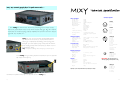
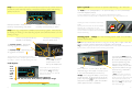
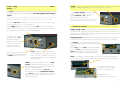
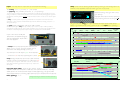
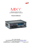
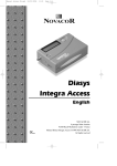
© 2007 AETA Audio Systems www.aeta-audio.com 12 55 000 055-B 1 OK, So smart people don’t read manuals … Mic/Line inputs … but MIXY is smart too. Don’t be fooled by her simple looks, there’s a great deal more to her than meets the eye. By all means treat her as a thoroughly stereo-capable mixer but not as a stereotypical one. Read on…. Max gain (Mic) Max gain (Line) Max input level Equivalent input noise Input headroom Balance adjustment High Pass Filter Limiter L/R path gain matching Frequency response Crosstalk Analogue Ouptuts MIXY can run on her internal rechargeable battery (for more than 10 hours) or on external 8-18VDC. When you unpack her the battery will be only partcharged. You will need to plug in the external mains power supply at the HR4 connector for about 4 hours to recharge it fully. MIXY will operate normally while recharging on external power. Turn MIXY on by holding the Esc button down for >2 seconds Her screen will light up. Nominal output level Maximum output level Output noise THD+N Headphone output M/S matricing Matrix accuracy (M+S) / (M-S) Stereo stage width Stereo reverse Connector pinouts +92dB +30dB +19dBu -128dBu (80dB gain) 37dB ±5dB 50Hz 18dB/oct 120Hz 18dB/oct 300Hz 6dB/oct Attack 1ms Release 0.2s ±0.5dB ±0.25dB (20Hz—20kHz) ±1dB (20Hz—40kHz Fs 96kHz) <-60dB XLR3 1 2 3 XLR5 1 5 3 1 L TX out 2 DC out 3 Ground 4 Ground 5 R TX out 6 IN3 Hi 7 In3 Lo 8 9V out—(max 100mA) 9 IN2 Hi 10 Power ground 11 In 2 Lo 12 Ext detect 1 Better than 1% >50dB steplessly adjustable 50—180° (110° centre) Polarity inverter on S channel Digital connections 32 / 44.1 /48 / 96kHz Bit depth USB 1.1 Bit depth 24 bit 32 /44.1 /48 kHz (set by host) 16 bit General External power Operation Battery charge Dimensions Weight 8-18VDC <300mA <2A 164 x 49 x 126mm (171 x 49 x 131mm inc connectors) 1.2kg measured over 20— 20—20kHz bandwidth unless otherwise annotated 1 Ground 2 L Hi 3 L Lo 4R Hi 5 R Lo Minicon +4dBu / -10dBV / Mic level (–46dBu) -10 to +22dBu -90dBu <0.1%, -80dB @1kHz Zl >16Ω (fully protected) AES/SPDIF/Toslink Sampling rate 1 Ground 2 Hi 3 Lo 4 1 HR10HR10-4 1 Power ground 2 Power ground 3 8-18VDC 4 8-18VDC BEWARE! BEWARE! Never shortshort-circuit pins 1 or 2 with other (signal) ground connections on MIXY 1 6 HR10HR10-6 1 Out Pre 1 2 AES out Hi 3 AES out Lo 4 Out Pre 2 5 Ground 6 Out Pre 3 Hold down the ESC button for >2 seconds to turn MIXY off. 2 11 USB Line Out Ext. I/O PAD 40dB 0/+20 dB Meter int/det Ch 1..3 RTN To set up MIXY press the Esc button briefly – the meter display will change to a menu. USB IN3 IN1 IN2 BUS L/C/R Routing OUT USB R Monitor Source Select USB Interface L/C/R Routing USB L Tone D A Monitor Mode Select OUT R OUT L A M/S dec D Digital Audio Rx Toslink I/F Digital Audio Tx SYNC IN1 IN2 IN3 Optical Out It’s quite OK to peek at menus and settings while MIXY is handling audio – you won’t affect the sound just by looking. GGpGzG G pGXGMGYGtG G h Gp/ Use the joystick to select the option you want, R Monitoring point Slate Ch 3 ϕ Ch 2 ϕ and then press the Left button to enter that menu. On/Off RTN2 RTN1 IN3 IN2 IN1 DC You can navigate up, down and across lists using the joystick. If you meet a >sign there are further options for you to scroll to. 8-18V DC Line In 3 Change the highlighted item or value using the joystick – and press the Left button to confirm the change. Press Esc to leave a menu – and repeat the press to return to the meter screen at any time. P12 P48 T12 Off Rx1 Ext. I/O Rx2 P12 P48 T12 Off PAD 20dB Charger Highlight an item to change by pressing the Left button – the item will flash. 2 1 GGGGGGGGGGGGGGGG pG zG QGpGXGMGYGtG GG h Gp/ GG pGzG QGpGXGMGYGtG GG h Gp/ 15 / 120 / 300 Hz 0..50dB (10 dB steps) HPF P12 P48 T12 Off 2 channel audio signal Differential signal L/R/C L/R/C L/R/C L/R/C Balance / S width Coupling (Stereo/MS) ϕ Invert Ch 1 M/S dec L/R/C Route L OVLD Mic power 10 There are 9 memories so that you can quickly switch between different sets of parameters if you need to use MIXY in a variety of ways. BUS Lim MIXY block schematic diagram Direct & Dig.Out SPDIF In PAD 40dB Tx2 Tx1 Unlike most portable mixers MIXY is largely controlled through her display screens. Take a little time to explore them. Once you have decided the way you want to work you can store the settings and MIXY will remember them. You can turn her off and when she starts again the settings will have been retained unchanged. 3 Inputs : all three XLR-3 inputs can be controlled individually. Set routing: routing L, R , C (=L+R), or – (not routed) Set powering: powering T12 (tonader), P12, P48, or – (no powering). T12 must only be used with microphones marked as such. Phantom power microphones will normally use P48 but if rated for P12 this option will be more economical of battery power. Dynamic microphones, including ribbons, might be safe with P12, P48 but it is wiser to turn the mic powering off. If MIXY is turned off with mic powering enabled she will ask if this is OK when she is next switched on. This is to prevent accidental damage. Press the PAD button briefly to confirm – or change the settings. Set gain: gain select preamplifier gain from 0dB to 50dB. With 0dB preamp gain MIXY has up to 40dB of gain to the line outputs. Adding 50dB of switched gain (90dB total) will give an input suitable for very low sensitivity microphones such as ribbons. In the 0dB gain position inputs as high as Line level can be accommodated. MIXY comes with her factory–default setting which you can always return to and also nine selectable memories which you can use to preset. As you work with Mixy you might find she has a few clever tricks up her sleeve. Try a double-click of the joystick to get to the Inputs menu quickly... Mic/Line input level map dBu +40 +30 Input 3 can have a 20dB pad (attenuator) inserted directly before the preamplifier. Press PAD— an P icon appears. +20 M/ Select the memory where you want to store your settings. Highlight and confirm with the Left button. MIXY’s memory status is shown by the tG GGGGGGGGGGGsGtXG GGGGGGGGGGGzGtXG Input +39 +19 Limiter +19 Max input level 0 -18 -18 -18 -36 -36 -36 -18 -18 -18 -18 -36 -36 ... and turns red when the signal begins to limit. Min gain -36 -36 Std output level (-18dBFS) High(HPF) F) - there are four options. None(-), High-pass filters (HP 50(50Hz,18dB/oct, 120(120hz, 18db/oct), 300 (300hz, 6dB/oct). The steep 18dB options cut windnoise and traffic rumble effectively. The gentle 6dB slope compensates for proximity effect (bass tip-up) in directional microphones. Phase (polarity) - + or 4 M/S decoder active -42 -60 Max gain -70 -80 -90 -86 -86 -88 -98 -98 -106 -106 -106 -110 Noise floor (minimum gain, fader low) -120 -130 -128 -128 MIXY MIXY always checks the input level to each channel. If there is a risk of overload the OVL LED lights red. The LED begins to light at –12dB below overload. If it does more than flash occasionally go back to the input set-up screen and reduce gain. -18 -24 -100 The channel LIM LED lights green when selected... Bus=> Digital dBFS Max output level -50 A limiter can be inserted into each channel, postfader. N=no, Y=yes, YC=yes coupled—this is automatic with stereo pairing of Ch 1 & 2. M/S decode +19 PAD on -30 -40 Fader +2 -10 -20 HPF & Direct o/p PAD on +19 +10 0 Preamp PAD (In3) Line output level map Digital (dBFS) Matrixing Unbalanced output Line out +22 +16 +16 Max level 0 M/S matrixing -18 Std level 0 +10 -6 -2 +4 Max gain (setting =22dBu) dBu +30 +20 +10 0 -10 -20 -18 Min gain (setting -9dBu) -27 -33 -30 -40 Output pad (-40dB) -50 -60 Always confirm your selection with the Left button -67 -70 9 MIXY shows the status of her input channels through the use of small icons at the bottom of the metering display. Microphone powering, filter and polarity (phase) are shown. Inputs 1 & 2 mode: mode these channels can operate independently or as a stereo pair. Set mode to: 2 Ch (independent), L/R (normal stereo), or M/S (Mid/Side or sum and difference stereo). In stereo modes channel 1 fader is not used—the Ch2 fader becomes the master. The outer concentric control provides +/-5dB balance (ch2 ) in L/R or stereo width in M/S. Example: Ch1 HPF= 120Hz, P12 mic powering, reverse polarity (180° phase) Example: Ch3 HPF= 300Hz, T12 mic powering, normal polarity (0° phase) MIXY has a very comprehensive headphone monitoring system. While the meter display is visible you can select any signal source and also listen to it in a variety of ways. Monitor source and mode are labelled on the display The level is controlled by the front panel knob. Linking of limiters is automatic in both stereo modes. Routing is also automatic but can be modified manually for L/R mode (but not M/S). Gain setting is automatic for L/R but not for M/ S since M and S microphones often have different inherent sensitivity. Auxiliary Inputs - MIXY has three auxiliary inputs, USB, Line (XLR5F) and the digital SPDIF. USB can be routed to the mix bus: L only (L), R only (R) or L&R. It can also be left unrouted (-)which still allows the signal to be monitored. The monitor source is selected by sideways joystick movements. Mixy automatically recognises USB signals and decodes them to their original analogue levels. It does not matter what the sample rate was when they were recorded. The monitor mode mode is selected by vertical joystick movements. The joystick can be “locked” against accidental changes. Push to lock—and push again to unlock. If not used for ~3 secs it will automatically lock itself. Mode sequence: M/S M- S M+S L+R L+R R/R L/L L/R I 8O/ MIXY has a low impedance (16Ω) monitor output which is suitable for all headphones. Some modes are not relevant for all sources (only L+R is logical for a mono input) so Mixy will change mode to suit these but will remember the previous setting. Source sequence: IN3, IN2, IN1&2 &2 IN2, IN1, OUT, RTN (return), USB, BUS, IN1 Monitor mode and source reselection have no effect on MIXY’s programme outputs . 8 The Line input can also be routed to the mix bus: L or R to L, L or R to R, l+ R to both ©. Alternatively it can be left unrouted (-) but it will still be available for monitoring. MIXY has no physical fader to control the signal level but an alignment level can be preset. Highlight Level to set the maximum theoretical level between –9dBu and 22dBu (EBU reference level is –18dBFS). The Digital In SPDIF signal (from the RCA connector) can be routed to the analogue outputs and replaces any other signal source routed there. Whether routed or not a valid signal at the SPDIF will synchronize Mixy’s AES/EBU output (Sync). If MIXY is the master (mistress?) digital source then sync is not required. However if she is being used with digital video recorders or as part of a larger digital network it is better to put MIXY MIXY into slave mode and use external sync. 5 Outputs: Outputs MIXY has several outputs which can be configured on the Output Setting screen. The output is normally set to L/R. Under XLR5M highlight and select M/S to encode the output as sum and difference. This setting applies to all analogue outputs. The X/LR5 M output level can be adjusted in two ways—a fixed 40dB attenuator to match levels to nominal microphone inputs, and by presetting a maximum output level relative to 0dBFS. Highlight “Pad Pad L/R” L/R and select N/N (no attenuation), Y/N (-40dB L only), N/Y (-40dB R only), or Y/Y (-40dB both). To set MIXY ’s Maximum Output Level select MOL and adjust the level between –9dBu and +22dBu. The R output tracks the L but this can be overridden by selecting and adjusting the R independently. Whatever MOL is set at the XLR5M (but not the attenuator setting) is mimicked at the 3,5mm stereo mini-jack output, except that it unbalanced and 6dB lower. In the Output Settings screen select Rate (48k, 44.1k). 32k or 96k only in Ext sync. Select Consumer or Pro to set the appropriate AES frame flag. Word length is always 24bit. If Ext sync is selected the sample rate will be driven by the digital input. The Miscellaneous Settings screen is used for various “housekeeping” purposes. Battery Charge— Charge—MIXY MIXY normally charges her internal NiMH battery if an external 8-18VDC supply is plugged in. Charging requires more than 10W so if external power is limited (an auxiliary battery, for instance) it may be helpful to turn the charge off. Select Y or N. Display Brightness— Brightness—select the option and adjust the brightness with the joystick. There is also a choice for maximum brightness with “reverse” video—black text. Iso outputs of Ch1, 2 & 3 are available as Unbalanced outputs at MIXY’s HR10-6 connector. MIXY always translates her analogue output to a digital USB feed. The sample rate (44.1kHz or 48kHz) is governed by the host computer and the wordlength is always 16bit. MIXY also routes the analogue output to the 12pin Minicon with independent level control, primarily for use with radio TXs . Select “RF” and adjust MOL between –40dB and 14dBu. Inputs 2 & 3 can be selected to the Ext I/O for use with radio Rxs etc. Use the Miscellaneous Settings Settings menu, Ext I/o sub menu. Select None, In 2, In 3, or In 2&3 to suit. If an input is enabled on the Minicon it replaces the XLR feed. 6 MIXY is as much a digital mixer as an analogue one and she has two digital outputs, a balanced AES/EBU (AES3) and an optical TosLink The Left key is “soft” and can be assigned various functions. These only operate when the meter screen is displayed. Select L Key Key and then Boost (+20dB for headphone— PFL only), Tone (for analogue alignment tone), or Slate (identification from front panel microphone). B, T or S tallies appear to confirm the selection. MIXY can display two optional styles of monitoring screen. The standard (STD) one shows the two output channels with overload warning (-3dBFS) v}sG In “multi” mode three additional bars show the 3 input channels post-fader levels. Battery level and sample rate are always shown. 7 Outputs: Outputs MIXY has several outputs which can be configured on the Output Setting screen. The output is normally set to L/R. Under XLR5M highlight and select M/S to encode the output as sum and difference. This setting applies to all analogue outputs. The X/LR5 M output level can be adjusted in two ways—a fixed 40dB attenuator to match levels to nominal microphone inputs, and by presetting a maximum output level relative to 0dBFS. Highlight “Pad Pad L/R” L/R and select N/N (no attenuation), Y/N (-40dB L only), N/Y (-40dB R only), or Y/Y (-40dB both). To set MIXY ’s Maximum Output Level select MOL and adjust the level between –9dBu and +22dBu. The R output tracks the L but this can be overridden by selecting and adjusting the R independently. Whatever MOL is set at the XLR5M (but not the attenuator setting) is mimicked at the 3,5mm stereo mini-jack output, except that it unbalanced and 6dB lower. In the Output Settings screen select Rate (48k, 44.1k). 32k or 96k only in Ext sync. Select Consumer or Pro to set the appropriate AES frame flag. Word length is always 24bit. If Ext sync is selected the sample rate will be driven by the digital input. The Miscellaneous Settings screen is used for various “housekeeping” purposes. Battery Charge— Charge—MIXY MIXY normally charges her internal NiMH battery if an external 8-18VDC supply is plugged in. Charging requires more than 10W so if external power is limited (an auxiliary battery, for instance) it may be helpful to turn the charge off. Select Y or N. Display Brightness— Brightness—select the option and adjust the brightness with the joystick. There is also a choice for maximum brightness with “reverse” video—black text. Iso outputs of Ch1, 2 & 3 are available as Unbalanced outputs at MIXY’s HR10-6 connector. MIXY always translates her analogue output to a digital USB feed. The sample rate (44.1kHz or 48kHz) is governed by the host computer and the wordlength is always 16bit. MIXY also routes the analogue output to the 12pin Minicon with independent level control, primarily for use with radio TXs . Select “RF” and adjust MOL between –40dB and 14dBu. Inputs 2 & 3 can be selected to the Ext I/O for use with radio Rxs etc. Use the Miscellaneous Settings Settings menu, Ext I/o sub menu. Select None, In 2, In 3, or In 2&3 to suit. If an input is enabled on the Minicon it replaces the XLR feed. 6 MIXY is as much a digital mixer as an analogue one and she has two digital outputs, a balanced AES/EBU (AES3) and an optical TosLink The Left key is “soft” and can be assigned various functions. These only operate when the meter screen is displayed. Select L Key Key and then Boost (+20dB for headphone— PFL only), Tone (for analogue alignment tone), or Slate (identification from front panel microphone). B, T or S tallies appear to confirm the selection. MIXY can display two optional styles of monitoring screen. The standard (STD) one shows the two output channels with overload warning (-3dBFS) v}sG In “multi” mode three additional bars show the 3 input channels post-fader levels. Battery level and sample rate are always shown. 7 MIXY shows the status of her input channels through the use of small icons at the bottom of the metering display. Microphone powering, filter and polarity (phase) are shown. Inputs 1 & 2 mode: mode these channels can operate independently or as a stereo pair. Set mode to: 2 Ch (independent), L/R (normal stereo), or M/S (Mid/Side or sum and difference stereo). In stereo modes channel 1 fader is not used—the Ch2 fader becomes the master. The outer concentric control provides +/-5dB balance (ch2 ) in L/R or stereo width in M/S. Example: Ch1 HPF= 120Hz, P12 mic powering, reverse polarity (180° phase) Example: Ch3 HPF= 300Hz, T12 mic powering, normal polarity (0° phase) MIXY has a very comprehensive headphone monitoring system. While the meter display is visible you can select any signal source and also listen to it in a variety of ways. Monitor source and mode are labelled on the display The level is controlled by the front panel knob. Linking of limiters is automatic in both stereo modes. Routing is also automatic but can be modified manually for L/R mode (but not M/S). Gain setting is automatic for L/R but not for M/ S since M and S microphones often have different inherent sensitivity. Auxiliary Inputs - MIXY has three auxiliary inputs, USB, Line (XLR5F) and the digital SPDIF. USB can be routed to the mix bus: L only (L), R only (R) or L&R. It can also be left unrouted (-)which still allows the signal to be monitored. The monitor source is selected by sideways joystick movements. Mixy automatically recognises USB signals and decodes them to their original analogue levels. It does not matter what the sample rate was when they were recorded. The monitor mode mode is selected by vertical joystick movements. The joystick can be “locked” against accidental changes. Push to lock—and push again to unlock. If not used for ~3 secs it will automatically lock itself. Mode sequence: M/S M- S M+S L+R L+R R/R L/L L/R I 8O/ MIXY has a low impedance (16Ω) monitor output which is suitable for all headphones. Some modes are not relevant for all sources (only L+R is logical for a mono input) so Mixy will change mode to suit these but will remember the previous setting. Source sequence: IN3, IN2, IN1&2 &2 IN2, IN1, OUT, RTN (return), USB, BUS, IN1 Monitor mode and source reselection have no effect on MIXY’s programme outputs . 8 The Line input can also be routed to the mix bus: L or R to L, L or R to R, l+ R to both ©. Alternatively it can be left unrouted (-) but it will still be available for monitoring. MIXY has no physical fader to control the signal level but an alignment level can be preset. Highlight Level to set the maximum theoretical level between –9dBu and 22dBu (EBU reference level is –18dBFS). The Digital In SPDIF signal (from the RCA connector) can be routed to the analogue outputs and replaces any other signal source routed there. Whether routed or not a valid signal at the SPDIF will synchronize Mixy’s AES/EBU output (Sync). If MIXY is the master (mistress?) digital source then sync is not required. However if she is being used with digital video recorders or as part of a larger digital network it is better to put MIXY MIXY into slave mode and use external sync. 5 Inputs : all three XLR-3 inputs can be controlled individually. Set routing: routing L, R , C (=L+R), or – (not routed) Set powering: powering T12 (tonader), P12, P48, or – (no powering). T12 must only be used with microphones marked as such. Phantom power microphones will normally use P48 but if rated for P12 this option will be more economical of battery power. Dynamic microphones, including ribbons, might be safe with P12, P48 but it is wiser to turn the mic powering off. If MIXY is turned off with mic powering enabled she will ask if this is OK when she is next switched on. This is to prevent accidental damage. Press the PAD button briefly to confirm – or change the settings. Set gain: gain select preamplifier gain from 0dB to 50dB. With 0dB preamp gain MIXY has up to 40dB of gain to the line outputs. Adding 50dB of switched gain (90dB total) will give an input suitable for very low sensitivity microphones such as ribbons. In the 0dB gain position inputs as high as Line level can be accommodated. MIXY comes with her factory–default setting which you can always return to and also nine selectable memories which you can use to preset. As you work with Mixy you might find she has a few clever tricks up her sleeve. Try a double-click of the joystick to get to the Inputs menu quickly... Mic/Line input level map dBu +40 +30 Input 3 can have a 20dB pad (attenuator) inserted directly before the preamplifier. Press PAD— an P icon appears. +20 M/ Select the memory where you want to store your settings. Highlight and confirm with the Left button. MIXY’s memory status is shown by the tG GGGGGGGGGGGsGtXG GGGGGGGGGGGzGtXG Input +39 +19 Limiter +19 Max input level 0 -18 -18 -18 -36 -36 -36 -18 -18 -18 -18 -36 -36 ... and turns red when the signal begins to limit. Min gain -36 -36 Std output level (-18dBFS) High(HPF) F) - there are four options. None(-), High-pass filters (HP 50(50Hz,18dB/oct, 120(120hz, 18db/oct), 300 (300hz, 6dB/oct). The steep 18dB options cut windnoise and traffic rumble effectively. The gentle 6dB slope compensates for proximity effect (bass tip-up) in directional microphones. Phase (polarity) - + or 4 M/S decoder active -42 -60 Max gain -70 -80 -90 -86 -86 -88 -98 -98 -106 -106 -106 -110 Noise floor (minimum gain, fader low) -120 -130 -128 -128 MIXY MIXY always checks the input level to each channel. If there is a risk of overload the OVL LED lights red. The LED begins to light at –12dB below overload. If it does more than flash occasionally go back to the input set-up screen and reduce gain. -18 -24 -100 The channel LIM LED lights green when selected... Bus=> Digital dBFS Max output level -50 A limiter can be inserted into each channel, postfader. N=no, Y=yes, YC=yes coupled—this is automatic with stereo pairing of Ch 1 & 2. M/S decode +19 PAD on -30 -40 Fader +2 -10 -20 HPF & Direct o/p PAD on +19 +10 0 Preamp PAD (In3) Line output level map Digital (dBFS) Matrixing Unbalanced output Line out +22 +16 +16 Max level 0 M/S matrixing -18 Std level 0 +10 -6 -2 +4 Max gain (setting =22dBu) dBu +30 +20 +10 0 -10 -20 -18 Min gain (setting -9dBu) -27 -33 -30 -40 Output pad (-40dB) -50 -60 Always confirm your selection with the Left button -67 -70 9 USB Line Out Ext. I/O PAD 40dB 0/+20 dB Meter int/det Ch 1..3 RTN To set up MIXY press the Esc button briefly – the meter display will change to a menu. USB IN3 IN1 IN2 BUS L/C/R Routing OUT USB R Monitor Source Select USB Interface L/C/R Routing USB L Tone D A Monitor Mode Select OUT R OUT L A M/S dec D Digital Audio Rx Toslink I/F Digital Audio Tx SYNC IN1 IN2 IN3 Optical Out It’s quite OK to peek at menus and settings while MIXY is handling audio – you won’t affect the sound just by looking. GGpGzG G pGXGMGYGtG G h Gp/ Use the joystick to select the option you want, R Monitoring point Slate Ch 3 ϕ Ch 2 ϕ and then press the Left button to enter that menu. On/Off RTN2 RTN1 IN3 IN2 IN1 DC You can navigate up, down and across lists using the joystick. If you meet a >sign there are further options for you to scroll to. 8-18V DC Line In 3 Change the highlighted item or value using the joystick – and press the Left button to confirm the change. Press Esc to leave a menu – and repeat the press to return to the meter screen at any time. P12 P48 T12 Off Rx1 Ext. I/O Rx2 P12 P48 T12 Off PAD 20dB Charger Highlight an item to change by pressing the Left button – the item will flash. 2 1 GGGGGGGGGGGGGGGG pG zG QGpGXGMGYGtG GG h Gp/ GG pGzG QGpGXGMGYGtG GG h Gp/ 15 / 120 / 300 Hz 0..50dB (10 dB steps) HPF P12 P48 T12 Off 2 channel audio signal Differential signal L/R/C L/R/C L/R/C L/R/C Balance / S width Coupling (Stereo/MS) ϕ Invert Ch 1 M/S dec L/R/C Route L OVLD Mic power 10 There are 9 memories so that you can quickly switch between different sets of parameters if you need to use MIXY in a variety of ways. BUS Lim MIXY block schematic diagram Direct & Dig.Out SPDIF In PAD 40dB Tx2 Tx1 Unlike most portable mixers MIXY is largely controlled through her display screens. Take a little time to explore them. Once you have decided the way you want to work you can store the settings and MIXY will remember them. You can turn her off and when she starts again the settings will have been retained unchanged. 3 OK, So smart people don’t read manuals … Mic/Line inputs … but MIXY is smart too. Don’t be fooled by her simple looks, there’s a great deal more to her than meets the eye. By all means treat her as a thoroughly stereo-capable mixer but not as a stereotypical one. Read on…. Max gain (Mic) Max gain (Line) Max input level Equivalent input noise Input headroom Balance adjustment High Pass Filter Limiter L/R path gain matching Frequency response Crosstalk Analogue Ouptuts MIXY can run on her internal rechargeable battery (for more than 10 hours) or on external 8-18VDC. When you unpack her the battery will be only partcharged. You will need to plug in the external mains power supply at the HR4 connector for about 4 hours to recharge it fully. MIXY will operate normally while recharging on external power. Turn MIXY on by holding the Esc button down for >2 seconds Her screen will light up. Nominal output level Maximum output level Output noise THD+N Headphone output M/S matricing Matrix accuracy (M+S) / (M-S) Stereo stage width Stereo reverse Connector pinouts +92dB +30dB +19dBu -128dBu (80dB gain) 37dB ±5dB 50Hz 18dB/oct 120Hz 18dB/oct 300Hz 6dB/oct Attack 1ms Release 0.2s ±0.5dB ±0.25dB (20Hz—20kHz) ±1dB (20Hz—40kHz Fs 96kHz) <-60dB XLR3 1 2 3 XLR5 1 5 3 1 L TX out 2 DC out 3 Ground 4 Ground 5 R TX out 6 IN3 Hi 7 In3 Lo 8 9V out—(max 100mA) 9 IN2 Hi 10 Power ground 11 In 2 Lo 12 Ext detect 1 Better than 1% >50dB steplessly adjustable 50—180° (110° centre) Polarity inverter on S channel Digital connections 32 / 44.1 /48 / 96kHz Bit depth USB 1.1 Bit depth 24 bit 32 /44.1 /48 kHz (set by host) 16 bit General External power Operation Battery charge Dimensions Weight 8-18VDC <300mA <2A 164 x 49 x 126mm (171 x 49 x 131mm inc connectors) 1.2kg measured over 20— 20—20kHz bandwidth unless otherwise annotated 1 Ground 2 L Hi 3 L Lo 4R Hi 5 R Lo Minicon +4dBu / -10dBV / Mic level (–46dBu) -10 to +22dBu -90dBu <0.1%, -80dB @1kHz Zl >16Ω (fully protected) AES/SPDIF/Toslink Sampling rate 1 Ground 2 Hi 3 Lo 4 1 HR10HR10-4 1 Power ground 2 Power ground 3 8-18VDC 4 8-18VDC BEWARE! BEWARE! Never shortshort-circuit pins 1 or 2 with other (signal) ground connections on MIXY 1 6 HR10HR10-6 1 Out Pre 1 2 AES out Hi 3 AES out Lo 4 Out Pre 2 5 Ground 6 Out Pre 3 Hold down the ESC button for >2 seconds to turn MIXY off. 2 11 © 2007 AETA Audio Systems www.aeta-audio.com 12 55 000 055-B 1