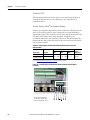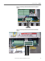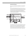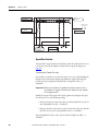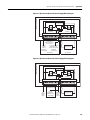
1
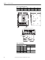
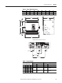
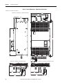
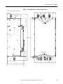
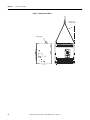
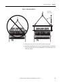
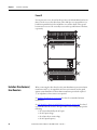
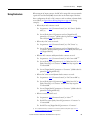
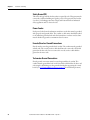
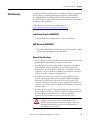
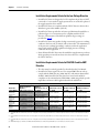
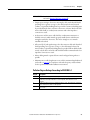
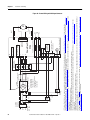
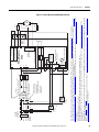
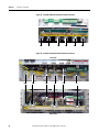
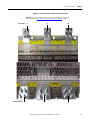
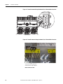
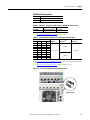
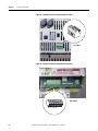
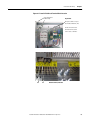
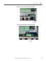
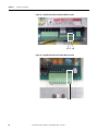
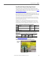
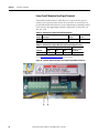
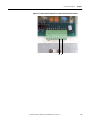
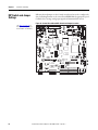
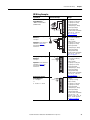
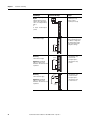
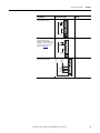
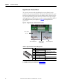
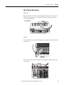
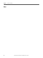
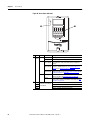
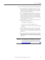
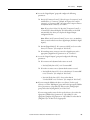
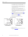
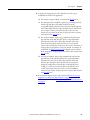
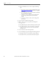
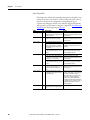
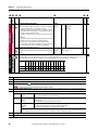
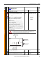
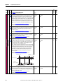
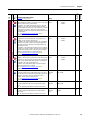
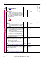
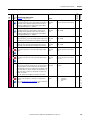
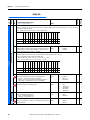
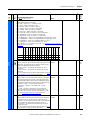
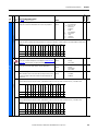
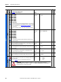
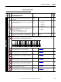
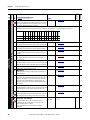
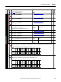
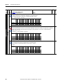
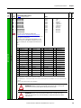
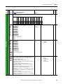
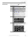
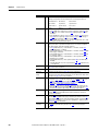
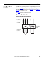
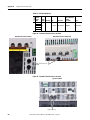
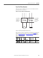
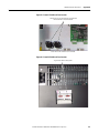
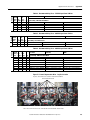
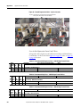
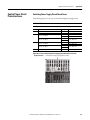
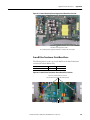
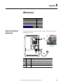
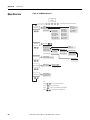
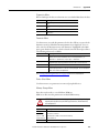
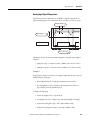
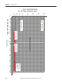
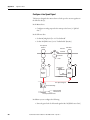
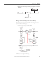
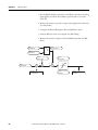
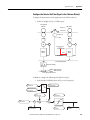
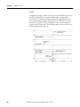
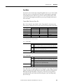
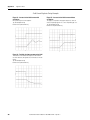
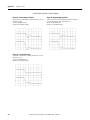
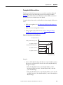
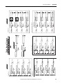
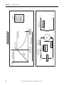
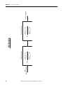
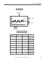
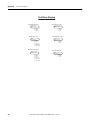
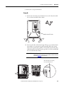
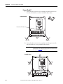
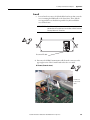
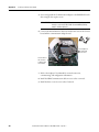
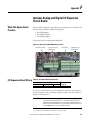
Appendix A
Supplemental Drive Information
Figure 61 - Frame B Switching Power Supply Circuit Board Fuse Location
Top View of Drive
Switching Power Supply circuit board fuse holders.
F1 = 3.15 A fuse
Rev. “H” and below only.
F2 = 2.5 A fuse
Rev. “H” and below only.
Figure 62 - Frame C Switching Power Supply Circuit Board Fuse Location
F1 = 3.15 A fuse
Rev. “H” and below only.
F2 = 2.5 A fuse
Rev. “H” and below only.
The Switching Power Supply circuit board is located on the back of the
Control board EMI shield.
238
Rockwell Automation Publication 20P-UM001H-EN-P - April 2011