1
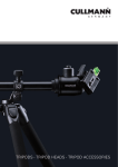
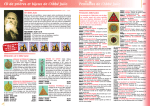
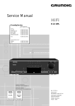
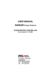
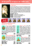
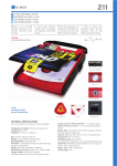
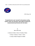
MAX300 Series
NanoMax 3-Axis Flexure
Stage
User Guide
Contents
Chapter 1 Safety ............................................................................................. 3
1.1 Safety Information .................................................................................. 3
1.2 General Warnings .................................................................................. 3
Chapter 2 Introduction ................................................................................... 4
2.1 Description of the NanoMax TS 3-Axis Flexure Stage ........................... 4
2.2 Component Identification ........................................................................ 4
Chapter 3 Operation ....................................................................................... 8
3.1 Manual Differential Drives and Differential Micrometer Drives ............... 8
3.2 NanoStep Motor Drives .......................................................................... 8
3.3 Piezo Actuators ...................................................................................... 9
Chapter 4 Installation ................................................................................... 10
4.1
4.2
4.3
4.4
4.5
4.6
4.7
4.8
Unpacking ........................................................................................... 10
Attaching to a Work Surface ................................................................. 10
Calibration of Motor Drives................................................................... 10
Fitting and Removal of Drives .............................................................. 11
Orienting the Moving Platform .............................................................. 12
Mounting Equipment. ........................................................................... 13
Transportation. ..................................................................................... 13
Dimensions ........................................................................................... 14
Chapter 5 Specifications ............................................................................. 17
Chapter 6 Parts and Consumables ............................................................. 18
6.1 Parts List .............................................................................................. 18
Chapter 7 Regulatory ................................................................................... 19
7.1 Declarations Of Conformity .................................................................. 19
7.2 Waste Electrical and Electronic Equipment (WEEE) Directive ............. 20
Chapter 8 Thorlabs Worldwide Contacts ................................................... 23
2
HA0094T Rev 11 April 2011
Chapter 1
Safety
1.1 Safety Information
For the continuing safety of the operators of this equipment, and the protection of the
equipment itself, the operator should take note of the Warnings, Cautions and Notes
throughout this handbook and, where visible, on the product itself.
The following safety symbols may be used throughout the handbook and on the
equipment itself.
Shock Warning
Given when there is a risk of injury from electrical shock.
Warning
Given when there is a risk of injury to users.
Caution
Given when there is a risk of damage to the product.
Note
Clarification of an instruction or additional information.
1.2 General Warnings
Warnings
If this equipment is used in a manner not specified by the manufacturer, the
protection provided by the equipment may be impaired. In particular,
excessive moisture may impair operation.
Spillage of fluid, such as sample solutions, should be avoided. If spillage does
occur, clean up immediately using absorbant tissue. Do not allow spilled fluid
to enter the internal mechanism.
3
Chapter 2
Introduction
2.1 Description of the NanoMax TS 3-Axis Flexure Stage
The NanoMax 3 axis flexure stage has been designed to integrate seemlessly into the
Thorlabs Modular Electronic System and provide nanometric positioning on three
orthogonal axes. It is suited to the alignment of optical fibres, waveguides,
optoelectronic packages and any other high resolution alignment or positioning
application including general purpose laboratory tasks. The innovative flexure design,
combined with the system of modular drives, offers exceptional performance and
flexibility.
Three types of drive are available, the DRV001 stepper motor drive, the DRV3
differential micrometer and the DRV004 thumbscrew. Also available are two external
piezo actuators which increase the piezo travel to 40 µm or 100 µm.
2.2 Component Identification
2.2.1 NanoMax Stage
The NanoMax-TS 3 axis flexure stage is available in three versions; piezo-actuated
with feedback on all axes, piezo-actuated without feedback and without piezo
actuation, as shown in Fig. 2.1 to Fig. 2.4.
SMC connectors
7-pin LEMO connectors
CAUTION
75 V DC MAX
DRIVE VOLT
AGE
P/N MAX301
Fig. 2.1 MAX301 NanoMax piezo-actuated stage with feedback on all axes
4
MAX300 Series 3-Axis Flexure Stages
SMC connectors
CAUTION
75 V DC MAX
DRIVE VOLTAGE
P/N MAX302
Fig. 2.2 MAX302 NanoMax piezo-actuated stage without feedback
The piezo-actuated models deliver 20 microns of travel, each piezo channel has a
coaxial SMC connector (see Fig. 2.1 and Fig. 2.2). In addition, the NanoMax 301 has
a 7-pin LEMO connector for each feedback channel (see Fig. 2.1). A corresponding
number of leads for connection to the Thorlabs piezoelectric controllers are also
supplied.The piezo-actuated models deliver 30 microns of travel, with a coaxial SMC
connector for each piezo channel.
The pin functions for the Lemo connectorare detailed below.
5
4
6
1
7 2
3
Pin
Description
1
2
3
4
5
6
7
+15 V
Oscillator +
0V
Sig Out Sig Out +
-15 V
Travel
Fig. 2.3 Feedback Lemo connector pin functions
5
Chapter 2
CAUTION
75 V DC MAX
DRIVE VOLTAGE
P/N MAX303
Fig. 2.4 MAX303 NanoMax without piezo-actuation
The NanoMax 303 has no electrical connections.
2.2.2 Drives and Actuators
There are three types of drive available for the NanoMax, a motorized drive as shown
in Fig. 2.5. and two manual drives as shown in Fig. 2.6. In addition, external piezo
actuators are available to give an additional 20 µm or 80µm piezo travel – see Fig. 2.7..
Note
The DRV001 stepper motor drive must be used in conjunction with the BSC
benchtop driver or the MST601 control module. It cannot be driven by the
TST001 T-Cube driver.
Fig. 2.5 DRV001 NanoStep motor drive
6
HA0094T Rev 11 April 2011
MAX300 Series 3-Axis Flexure Stages
DRV3 differential micrometer drive
DRV004 thumbscrew drive
Fig. 2.6 Manual Drives
These external piezo actuators can be fitted in-line with the standard drives described
on the previous page. The DRV120 provides an additional 20 µm of piezo travel. The
DRV181 gives 80 µm of travel.
DRV120
External piezo actuator
with feedback
8
DRV181
External piezo actuator
without feedback
Fig. 2.7 External piezo actuators
7
Chapter 3
Operation
3.1 Manual Differential Drives and Differential Micrometer Drives
3.1.1 Adjusting Micrometer Drives
Turn the coarse adjustment clockwise until the platform of the NanoMax begins to
move. By use of the fine adjustment, sub-micron resolution is now achievable.
3.1.2 Reading Micrometer Drives
50 μm per rev
1.0 μm per division
coarse adjuster (8 mm)
(4 mm on stage)
fine adjuster (300 μm)
Fig. 3.1 Reading micrometer drives
3.2 NanoStep Motor Drives
When used together with a Thorlabs stepper motor Controller, the NanoStep motor
drives allow fully automatic control of the NanoMax.
Basic steps in controlling the stage are as follows:
1) Set commands to configure each axis (setting velocities, accelerations etc.) – see
the handbook for relevant stepper motor controller.
2) Move each axis to its home position, to establish a zero datum.
3) Set commands to move each axis by relative and absolute amounts – see
APTServer Helpfile.
A default configuration is set at the factory and stored in the non-volatile memory of
the motor controller – see Table 3.1.
8
MAX300 Series 3-Axis Flexure Stages
Table 3.1 Standard configurations for motor drives
Parameter
Value
Maximum Velocity
2.5 mm s-1
Minimum Velocity
1 mm s-1
Slope
1 mm s-2
1
–0.01 mm
Linear
40000
3 mm
0.00 mm
4.00 mm
Backlash control
Backlash distance
Mode
Microsteps to units
Offset
Minimum position
Maximum position
Notes
The NanoStep modular drives have no +ve limit switch. The drive reaches
a mechanical stop at a position dependent on the axis to which it is
attached. The design is such that occasional driving into the stop will not
cause any damage.
If the axis is driven towards the –ve limit switch, at a certain position the
platform stops moving while the drive itself continues to move until the
limit switch is reached. The drive must then be moved positively by a
certain distance before the platform begins to move. This distance is just
less than the offset.
When creating a program to control the NanoMax, it is preferable to avoid
running into the +ve limit.
3.3 Piezo Actuators
Piezo actuators are used to give nanometric positioning of the top platform over a
range of 20 microns (40 µm or 100 µm if external piezo actuators are used). They can
also modulate the position of the platform at high frequency.
On a piezo-actuated NanoMax, position feedback may be incorporated on the linear
axes to enhance the repeatability and linearity of piezo motion.
The piezo-actuated NanoMax should be used together with one of the Thorlabs
piezoelectric controllers – see the handbook for the relevant piezoelectric controller.
The NanoMax monitors the ambient temperature using thermistors and applies small
movements to the stage to compensate for the expansion and contraction of metals
within the stage. Note that this compensation is active only when the associated piezo
controller is set to ‘closed loop’ (feedback on) mode – see the relevant piezo controller
handbook for more details on the operation of piezo actuators.
9
Chapter 4
Installation
4.1 Unpacking
Note
Retain the packing in which the unit was shipped, for use in future
transportation.
Caution
Once removed from its packaging, the NanoMax is easily damaged by
mishandling. The unit should only be handled by its base, not by the top
platform or any attachments to the top platform.
4.2 Attaching to a Work Surface
The base of the NanoMax is provided with a number of fixing holes and slots for
attachment to metric or inch optical tables, as supplied by Thorlabs and other
manufacturers. Bolting the unit down minimizes the risk of damage from dropping.
When mounting the NanoMax close to other equipment, ensure that the travel of the
moving platform is not obstructed. If the moving platform is driven against a solid
object, damage to the internal flexures could occur. The range of travel on each axis
is 4 mm total, that is ± 2 mm about the nominal position.
4.3 Calibration of Motor Drives
Note
This section is applicable only to motor drives when a calibration has
been requested.
Calibration enables the server to correct for any mechanical errors inherent in the
system. Mechanical components, such as the leadscrew and linkages, can be
machined only within a certain tolerance, e.g. the leadscrew may be nominally 1mm
but actually 1.0005mm, giving a 0.5 micron error. In practice, these errors accumulate
from a number of sources, however they are repeatable and therefore, can be
compensated.
During calibration, the total positional error is measured at a large number of points
and these errors are stored as a look up table (LUT). The LUT is saved as a
calibration file, one file for each axis on a particular stage. These files are then linked
to the appropriate axis as part of the Stage association process performed using the
APT Config utility. Whenever the stage is moved, the LUT is consulted to ascertain
the precise movement required to achieve the demanded position.
10
MAX300 Series 3-Axis Flexure Stages
When the stage is calibrated at the factory, the stepper motor controller, channel
number, motor, stage and axis are configured in a certain manner. For the calibration
to be effective, it is important to re-assemble the stage with the motors fitted to the
same axis for which they were calibrated. This information is contained in the table
below.
Furthermore, the correct calibration files must be associated with the correct stage
axis. In this regard, it is important to confirm what stage axes are connected to
particular channels on particular motor units. It is then a simple task to use the APT
Config utility to associate the correct calibration file with a particular serial numbered
hardware unit and channel.
The use of a calibration file is optional. Without it, the repeatability and resolution of
the stage are unaffected, but no compensations are made to enhance the accuracy
Details on assigning a calibration file are contained in the APTConfig On Line Helpfile.
Table 4.1 Calibration details
NanoMax serial number
Axis
Motor Serial number Calibration File
X
Y
Z
Remarks
4.4 Fitting and Removal of Drives
This section is applicable only to Part Numbers MAX301, MAX302 and MAX303.
The following procedure details how to fit a drive to the NanoMax 300 stage. A
micrometer drive is shown for illustration purposes but the procedure is equally
applicable to motor or thumbscrew actuators.
1) For manual drives, rotate the coarse adjuster counter-clockwise a few turns to
retract the drive rod. For motor drives, retract the drive rod by turning the manual
adjuster clockwise.
Then, referring to Fig. 4.1 on the next page...
2) Insert the drive into the mounting bush.
3) Tighten the knurled locking ring until finger tight.
Note
To remove a drive reverse the above procedure.
When removing a motor drive, rotate only the locking ring, do not rotate
the motor body.
11
Chapter 4
mounting
lock ring
coarse adjustment
locking screw
fine adjustment
moving
plate
coarse adjustment
mounting bush
fixed body
drive rod
Fig. 4.1 Micrometer drive inserted into mounting bush
4.5 Orienting the Moving Platform
The stage is normally oriented such that the X axis is the optical axis. If it is necessary
to change the orientation for left or right-handed use, the Y axis becomes the optical
axis as shown in Fig. 4.2 (The Z axis is always vertical).
X
Optical axis
Z
X
Y
Z
Y
left handed
right handed
Fig. 4.2 Platform orientation
12
HA0094T Rev 11 April 2011
MAX300 Series 3-Axis Flexure Stages
4.6 Mounting Equipment.
Caution
When attaching accessories (e.g. fiber holders) to the top platform or
angle brackets (e.g. AMA007 and AMA009) to the side of the unit, do not
use long bolts which protrude into the internal mechanism as this could
cause damage to the internal flexures.
The weight attached to the moving platform must not exceed 1 kg.
Do not apply excessive forces to the moving platform.
Thorlabs manufacture a variety of fibre chucks, holders and fixtures to fit the
NanoMax stage. However, custom hardware can be designed using a tongue-ingroove arrangement and the cleats provided, see Fig. 4.3 for a typical fixture.
all dimensions in mm
optical axis
3.0 (0.12)
typical
slot each side for mounting cleats
P
as required
3.0 (0.12)
3.0 (0.12)
typical
1.3 (0.05)
14.55 (0.57)
2.95 (0.12)
32.0 (1.26)
Fig. 4.3 Typical fixture, view along X-axis, length as required
4.7 Transportation.
Caution
The drives should be removed before transporting the NanoMax.
When packing the unit for shipping, use the original packing. If this is not
available, use a strong box and surround the NanoMax with at least 100
mm of shock absorbent material.
13
Chapter 4
4.8 Dimensions
4.8.1 Top Platform
60.0 (2.36)
all dimensions in millimetres (inches)
3 Pitches of 15.00 (0.59) = 45.0
7.5
(0.3)
17.0 (0.67)
17.0 (0.67)
10.0 (0.39)
4.0 (0.16)
10.0 (0.39)
30.0 (1.18)
3.0 (0.12)
17.0 (0.67)
5.3 (0.21)
5.3 (0.21)
17.0 (0.67)
10.0 (0.39)
20.0 (0.79)
20.0 (0.79)
10.0 (0.39)
(0.3)
3 Pitches of 15.00 (0.59) = 45.0
7.5
60.0 (2.36)
1.6 (0.06)
5.3 (0.21)
5.3 (0.21)
20.0 (0.79)
20.0 (0.79)
30.0 (1.18)
(0.06)
1.6
3.00 (0.12)
A
60 (2.36)
7.5
(0.3)
20
(0.79)
60
(2.36)
20
(0.79)
B holes M3 (6-32 UNC)
Product No
AMA001
AMA003
AMA005
A
28 (1.10
35 (1.38)
45 (1.77)
B
12 (0.47)
12 (0.47)
14 (0.55)
extended top platform
Fig. 4.4 Dimensions – top platform
14
HA0094T Rev 11 April 2011
MAX300 Series 3-Axis Flexure Stages
4.8.2 External Piezo Actuators
DRV120: 82.0 nominal
26.0 ±4
nominal
reach
DRV181: 126.0 nominal
Fig. 4.5 External piezo actuators
4.8.3 Modular Drives
all dimensions in millimetres (inches)
112.5 (4.43)
42.0 (1.65)
DRV001
stepper motor drive
26.0 ±4
(1.02 ±0.16)
nominal reach
1.13
(28.7)
nominal
reach
2.24
(56.8)
DRV3 micrometer
differential drive
0.31 (8.0)
Travel
27.5 (1.08)
Ø19 (0.75)
DRV004
thumbscrew drive
26.0 ±4
(1.02 ±0.16)
nominal reach
Fig. 4.6 Dimensions – modular drives
15
Chapter 4
4.8.4 NanoMax 3-Axis Stage
all dimensions in millimetres (inches)
1.7
(0.06)
11
30
(1.18) (0.43)
42.6
30
(1.18) (1.68)
56.5
(2.22)
3.0
(0.12)
87 (3.43)
98
(3.86)
112
(4.41)
93 (3.66)
105.6 (4.16)
17.4 (0.69)
4.8 (0.19)
62.5
(2.46)
105.6 (4.16)
93 (3.66)
42
(1.65)
21
(0.83)
87.0
(3.43)
98.0
(3.86)
Fig. 4.7 Dimensions – NanoMax 3-axis stage
16
HA0094T Rev 11 April 2011
MAX300 Series 3-Axis Flexure Stages
Chapter 5
Specifications
..
Parameter
Weight (without drives):
Load capacity:
Travel
Resolution
Arcuate displacement (maximum):
Value
800 g
1 kg
Manual (coarse) and motor4 mm
Manual (fine)300µm
Piezo20 micron
Manual (coarse)0.5mm per revolution
Manual (fine)50µm per revolution
Motor0.06 µm min incremental movement
Piezo (without feedback)20 nm
Piezo (with feedback)5 nm
80 micron
Note
The resolution of a manual drive corresponds to a 0.5 degree adjustment
of the thimble; the actual resolution obtained depends on the skill of zthe
user. The resolution of the motor drives is the smallest step that can be
executed (i.e. 1 microstep). The resolutions of the piezo actuators are
those typically obtained using Thorlabs controllers.
Power supply
Piezoactuated NanoMax
Nominal maximum input voltage:75 V
Stepper Motor
Absolute maximum input voltage:100 V
Maximum input voltage:24 V
Caution
The NanoMax should only be used in conjunction with the appropriate
Thorlabs Piezoelectric Controllers.
17
Chapter 6
Parts and Consumables
6.1 Parts List
Part Number
Description
MAX316D and MAX316D/M
MAX315D and MAX315D/M
NanoMax stage with differential micrometer drives
NanoMax stage with piezo actuator and differential
micrometer drives
NanoMax stage with feedback piezo actuator and
differential micrometer drives.
NanoMax stage with stepper motor drives.
NanoMax stage with piezo actuator and stepper motor
drives.
NanoMax stage with feedback piezo actuator and
stepper motor drives.
NanoMax stage only
NanoMax stage with piezo actuator
NanoMax stage with feedback piezo actuator.
SMC connector lead
LEMO connector lead
Mounting cleat
Cable clamp
Handbook
MAX314D and MAX314D/M
MAX343 and MAX343/M
MAX342 and MAX342/M
MAX341 and MAX341/M
MAX303 and MAX303/M
MAX302 and MAX302/M
MAX301 and MAX301/M
166038
134667
131030
120992
ha0094T
18
Chapter 7
Regulatory
7.1 Declarations Of Conformity
7.1.1 For Customers in Europe
This equipment has been tested and found to comply with the EC Directives
89/336/EEC ‘EMC Directive’ and 73/23/EEC ‘Low Voltage Directive’ as amended by
93/68/EEC.
Compliance was demonstrated by conformance to the following specifications which
have been listed in the Official Journal of the European Communities:
Safety
EN61010: 2001 Installation Category II, Polution Degree II.
EMC
EN61326: 1997
7.1.2 For Customers In The USA
This equipment has been tested and found to comply with the limits for a Class A
digital device, persuant to part 15 of the FCC rules. These limits are designed to
provide reasonable protection against harmful interference when the equipment is
operated in a commercial environment. This equipment generates, uses and can
radiate radio frequency energy and, if not installed and used in accordance with the
instruction manual, may cause harmful interference to radio communications.
Operation of this equipment in a residential area is likely to cause harmful interference
in which case the user will be required to correct the interference at his own expense.
Changes or modifications not expressly approved by the company could void the
user’s authority to operate the equipment.
19
Chapter 7
7.2 Waste Electrical and Electronic Equipment (WEEE) Directive
7.2.1 Compliance
As required by the Waste Electrical and Electronic Equipment (WEEE) Directive of
the European Community and the corresponding national laws, we offer all end users
in the EC the possibility to return "end of life" units without incurring disposal charges.
This offer is valid for electrical and electronic equipment
•
•
•
•
•
sold after August 13th 2005
marked correspondingly with the crossed out "wheelie bin" logo (see Fig. 1)
sold to a company or institute within the EC
currently owned by a company or institute within the EC
still complete, not disassembled and not contaminated
Fig. 7.1 Crossed out "wheelie bin" symbol
As the WEEE directive applies to self contained operational electrical and electronic
products, this "end of life" take back service does not refer to other products, such as
•
•
•
•
pure OEM products, that means assemblies to be built into a unit by the user (e. g.
OEM laser driver cards)
components
mechanics and optics
left over parts of units disassembled by the user (PCB's, housings etc.).
If you wish to return a unit for waste recovery, please contact Thorlabs or your nearest
dealer for further information.
7.2.2 Waste treatment on your own responsibility
If you do not return an "end of life" unit to the company, you must hand it to a company
specialized in waste recovery. Do not dispose of the unit in a litter bin or at a public
waste disposal site.
20
HA0094T Rev 11 April 2011
MAX300 Series 3-Axis Flexure Stages
7.2.3 Ecological background
It is well known that WEEE pollutes the environment by releasing toxic products
during decomposition. The aim of the European RoHS directive is to reduce the
content of toxic substances in electronic products in the future.
The intent of the WEEE directive is to enforce the recycling of WEEE. A controlled
recycling of end of life products will thereby avoid negative impacts on the
environment.
21
22
Chapter 8
Thorlabs Worldwide Contacts
USA, Canada, and South America
Thorlabs, Inc.
435 Route 206
Newton, NJ 07860
USA
Tel: 973-579-7227
Fax: 973-300-3600
www.thorlabs.com
www.thorlabs.us (West Coast)
email: [email protected]
Support: [email protected]
Europe
Thorlabs GmbH
Hans-Böckler-Str. 6
85221 Dachau
Germany
Tel: +49-(0)8131-5956-0
Fax: +49-(0)8131-5956-99
www.thorlabs.de
email: [email protected]
UK and Ireland
Thorlabs Ltd.
1 Saint Thomas Place, Ely
Cambridgeshire CB7 4EX
Great Britain
Tel: +44 (0)1353-654440
Fax: +44 (0)1353-654444
www.thorlabs.de
email: [email protected]
Support:
[email protected]
Scandinavia
Thorlabs Sweden AB
Box 141 94
400 20 Göteborg
Sweden
Tel: +46-31-733-30-00
Fax: +46-31-703-40-45
www.thorlabs.de
email: [email protected]
Japan
Thorlabs Japan Inc.
Higashi Ikebukuro
Q Building 1st Floor 2-23-2
Toshima-ku, Tokyo 170-0013
Japan
Tel: +81-3-5979-8889
Fax: +81-3-5979-7285
www.thorlabs.jp
email: [email protected]
China
Thorlabs China
Oasis Middlering Centre
3 Building 712 Room
915 Zhen Bei Road
Shanghai
China
Tel: +86 (0)21-32513486
Fax: +86 (0)21-32513480
www.thorlabs.com
email: [email protected]
France
Thorlabs SAS
109, rue des Côtes
78600 Maisons-Laffitte
France
Tel: +33 (0) 970 444 844
Fax: +33 (0) 811 381 748
www.thorlabs.de
email: [email protected]
23
Thorlabs Inc.
435 Route 206 North
Newton, NJ07860
USA
Tel: +1 973 579 7227
Fax: +1 973 300 3600
www.thorlabs.com
24
Thorlabs Ltd.
Saint Thomas Place, Ely
Cambridgeshire CB7 4EX,
UK
Tel: +44 (0) 1353 654440
Fax: +44 (0) 1353 654444
www.thorlabs.com