1
User’s guide
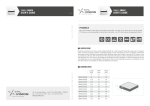
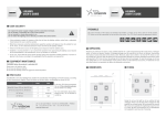
Dimensions
Length
(mm)
EBAR5
P2/4
fixing
Height
(mm)
P3/4
strobe mode
Width
(mm)
A
B
C
153
47
47
EBAR10
278
47
47
EBAR15
403
47
47
EBAR20
528
47
47
EBAR25
653
47
47
EBAR30
778
47
47
EBAR35
903
47
47
EBAR40
1028
47
47
EBAR45
1153
47
47
EBAR50
1278
47
47
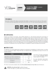
Dimming
Entrée
Triggering
Déclenchement
input
100%
80%
Set at equal
distance
60%
40%
20%
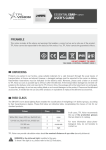
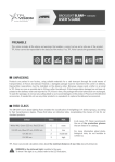
During the set up, the light has to be switched off and
unplugged. Please use the 2 delivered nuts and insert
them in the groove located in the back of the lighting.
The lighting will be better fixed if you spread the attachment points as indicated on the scheme above.
IP65 Option:
add 3 mm to the length above mentionned.
Timetable
We recommend the using of M8 screws (not supplied)
with a tightening torque from 0.5 to 1.5 Nm. We also
recommend the use of a threadlocker (not supplied) to
avoid any risk of loosening.
VOLTS
0%
0
1
2
3
4
5
6
1.5 ms
1 ms
Sortie
Lighting
Éclairage
output
Potential dimming between 1.5 and 5 Volts.
Above 5 Volts, the product reaches 100%
Power supply : 24V +/-10%
of its lighting power.
Strobe input : 24V or 5V TTL
Connection
M12 4 male points
Automate black
STROBE
+ 24 V
brown
4
3
blue
1
2
white
In STROBE mode:
STROBE entry = 24 V
or 5V TTL –> light on
FRONT VIEW
OF THE CONNECTOR
GND
NC
PNP-Like Automaton output
STROBE MODE CONNECTION
CONTINUOUS MODE CONNECTION
1 + 24 V
1 + 24 V
2
2
3 Ground
3 Ground
4 Strobe
4
NPN-Like Automaton output
Toward STROBE
input
From camera
/automate
+5V or +24V
Resistance value
to be adapted
to the automaton.
Max. 4.7 kΩ
+5V or +24V
0V
Toward STROBE
input
From camera
/automate