1
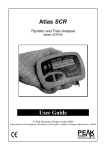
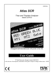
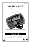
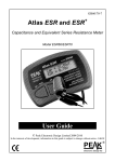
Atlas SCR
Thyristor and Triac Analyser
Model SCR100
User Guide
© Peak Electronic Design Limited 2004/2008
In the interests of development, information in this guide is subject to change without notice - E&OE
electronic design ltd
Atlas SCR User Guide
January 2008 – Rev 3
Want to use it now?
We understand that you want to use your Atlas SCR right now.
The unit is ready to go and you should have little need to refer
to this user guide, but please make sure that you do at least take
a look at the notices on page 4!
Contents
Page
Introduction .........................................................................3
Safety Considerations ..........................................................4
Analysing components.........................................................5
SCRs ..............................................................................6
Triacs..............................................................................7
Notes on SCRs (Thyristors) and Triacs ...............................8
Gate Sensitivity..................................................................10
Care of your Atlas SCR......................................................11
Battery Replacement ....................................................11
Self Tests......................................................................12
Appendix A – Accessories.................................................13
Appendix B – Technical Specifications.............................14
Warranty Information ........................................................15
Page 2
Atlas SCR User Guide
January 2008 – Rev 3
Introduction
The Atlas SCR is an advanced instrument designed specifically
for the analysis of SCR (Thyristor) and Triac devices.
Summary Features:
•
Automatic component identification.
•
Automatic pinout identification.
•
Displays actual trigger (gate) current classification.
•
Fixed load current of 100mA.
•
Device test voltage of 12V regardless of battery condition.
•
Suitable for devices requiring gate currents up to 90mA.
•
Automatic and manual power-off.
Page 3
Atlas SCR User Guide
January 2008 – Rev 3
Safety Considerations
WARNING:
This instrument must NEVER be connected to powered
equipment/components or equipment/components with any
stored energy (e.g. charged capacitors).
Failure to comply with this warning may result in personal
injury, damage to the equipment under test, damage to the
Atlas SCR and invalidation of the manufacturer's
warranty.
“Analysis of discrete, unconnected components is
recommended.”
The Atlas SCR is designed to provide accurate and reliable
information for the majority of supported component types
(SCRs and Triacs) as described in the technical specifications.
Testing of other component types or component networks may
give erroneous and misleading results.
Page 4
Atlas SCR User Guide
January 2008 – Rev 3
Analysing Components
The Peak Atlas SCR is designed to analyse discrete, unconnected, unpowered
components. This ensures that external connections don’t influence the
measured parameters. The three test probes can be connected to the component
any way round.
The Atlas SCR will start component analysis when the on/test button is
pressed.
Analysing...
The analysis typically takes less than a second to complete, after which the
results of the analysis are displayed. Information is displayed a “page” at a
time, each page can be displayed by briefly pressing the scroll/off button.
If the Atlas SCR cannot recognise the component connected to the test probes,
or the component under test is outside the specifications covered by this
instrument, the following message will
be displayed:
No SCR or Triac
detected
Note:
The arrow symbol on the display indicates that more pages are
available to be viewed.
Page 5
Atlas SCR User Guide
January 2008 – Rev 3
A
Silicon Controlled rectifiers (SCRs)
The Atlas will analyse almost any SCR provided that a gate trigger
current of no more than 90mA is required.
The three test clips can be connected to
the device under test any way round. If
the Atlas detects an SCR, the following
message will be displayed:
RED GREEN BLUE
Anod Cath Gate
G
K
SCR detected
Details follow
Pressing the scroll/off button will then
display the pinout details for the device.
In this example, the Anode of the SCR is connected to the Red test clip, the
Cathode is connected to the Green test clip, and the Gate terminal is connected
to the Blue test clip. The gate trigger current is displayed on the next screen.
Note that SCRs are often only specified
to have a certain maximum trigger
current – the actual (measured) trigger
current may be well below that value.
Trigger current
IG=50 to 75mA
The load current at which the SCR was
tested is also displayed. This value is
Tested at a load
fixed for all devices, and simply serves
current of 0.1A
symbol indicates
as a reminder. The
that this is the final page of information. Pressing the scroll/off button again
will return the display to the first page of information.
Page 6
Atlas SCR User Guide
January 2008 – Rev 3
MT2
Triacs
The Atlas will analyse almost any Triac, with the proviso that a G
MT1
gate trigger current of more than 90mA is not required. The
three test clips can be connected to the
device under test any way round. If the
Triac detected
Atlas detects a Triac, the following
Details follow
message will be displayed:
Note: The device under test will be analysed in quadrants 1 and 3. The
definition of these quadrants is given later in this guide.
RED GREEN BLUE
MT1 MT2 Gate
Pressing the scroll/off button will then
display the pinout details for the device.
In this example, the MT1 terminal of the Triac is connected to the Red test clip,
the MT2 terminal is connected to the Green test clip, and the Gate terminal is
connected to the Blue test clip. The gate
trigger current is displayed on the next
Trigger current
screen. Note that Triacs are often only
IG=25 to 50mA
specified to have a certain maximum
trigger current – the actual (measured)
trigger current may be well below that value.
The gate trigger current1 displayed is that for quadrant 3. (Quadrant 1 will
usually be very similar).
The load current at which the Triac was tested is also displayed. This value is
symbol indicates
fixed for all devices, and simply serves as a reminder. The
that this is the final page of information. Pressing the scroll/off button again
will return the display to the first page of information.
Note 1. See the “Gate Sensitivity” section later in this guide.
Page 7
Atlas SCR User Guide
January 2008 – Rev 3
Notes on SCRs and Triacs
Silicon Controlled Rectifiers
SCR Turn-On
SCRs (Thyristors) act as a controlled diode. They block reverse current at all
times, and they conduct in the forward direction only when triggered by a pulse
of current to the control (gate) terminal. Once triggered, the SCR will continue
to conduct current in the forward direction until the device is turned off.
SCR Turn-Off
In order to turn off a triggered SCR, it is necessary to reduce the main terminal
current below the holding current for typically 5-200µS. Shorter periods may
leave insufficient time for free charge carriers to recombine, and thus when
main current is reapplied, the device may remain triggered.
Page 8
Atlas SCR User Guide
January 2008 – Rev 3
Notes on SCRs and Triacs
Triacs
Triacs are a well established technology, designed specifically for the solidstate control of AC loads. They offer bi-directional load current switching (for
both half cycles of the mains supply) and also bi-directional gate current
capability to trigger the device. The combinations of the load currents and gate
control currents are referred to as “quadrants”. These quadrants are shown
below:
MT2 Positive (positive half cycle)
Quadrant 2
Quadrant 1
MT2
MT2
GT
GT
The main load current is
handled by the connections
MT1 and MT2. The device is
switched to the on state by a
current into (or out of) the
gate terminal with respect to
the MT1 terminal.
MT1
MT1
Quadrant 3
Quadrant 4
MT2
MT2
GT
GT
MT1
MT1
MT2 Negative (negative half cycle)
Once triggered, main load
current will continue to flow
until a zero-cross in the
mains cycle is encountered,
at this point the device
switches off. Therefore, if the
device is to be kept on, a
continuous gate current must
be provided or at least a gate
current pulse that occurs
immediately after each mains zero-cross.
Many triacs however are only capable of operating reliably in 3 of the 4
quadrants. (In particular, Q1, Q2 and Q3). Quadrant 4 (negative gate current
and negative load current) can be troublesome with some triacs, suffering from
poor gate sensitivity and slow response.
Page 9
Atlas SCR User Guide
January 2008 – Rev 3
Gate Sensitivity
The Peak Atlas SCR attempts to trigger the device under test at eight discrete
gate currents, in ascending order.
Trigger test level 1
100µA
Trigger test level 2
Trigger test level 3
Trigger test level 4
500µA
2.5mA
10mA
Trigger test level 5
Trigger test level 6
Trigger test level 7
25mA
50mA
75mA
Trigger test level 8
90mA
First test
Last test
Thus, for example, a reported trigger current of 10mA means that device
triggering occurred at a gate current of 10mA, but not at 2.5mA. Therefore the
trigger current for the device under test is between 2.5mA and 10mA.
Although Triacs are tested in both quadrants 1 and 3, the reported gate trigger
current (for both SCRs and Triacs) is that which applies to quadrant 3.
Page 10
Atlas SCR User Guide
January 2008 – Rev 3
Care of your Atlas SCR
The Peak Atlas SCR should provide many years
of service if used in accordance with this user
guide. Care should be taken not to expose your unit
to excessive heat, shock or moisture. Additionally, the battery
should be replaced at least every 12 months to reduce the risk of leak
damage.
Low Battery
If a low battery warning message
appears, replacement of the battery is
mandatory. The Atlas will not continue
to operate if this condition is
encountered.
New batteries can be purchased from many retailers and directly from Peak
Electronic Design Ltd or an authorised agent.
Battery types: Suitable battery types include 23A, V23A, GP23A, MN21 or a
good quality 12V alkaline equivalent as used in many test instruments and
automotive remote key fobs.
Battery access: To replace the battery, unscrew the three screws to remove the
rear panel. Remove the old battery and insert a new one, taking care to observe
the correct polarity. Carefully replace the rear panel, do not over-tighten the
screws.
Peak Safe Battery Disposal Scheme: Please return your old analyser battery to
Peak Electronic Design Ltd for safe and environmentally responsible disposal.
Page 11
Atlas SCR User Guide
January 2008 – Rev 3
Self Test Procedure
Each time the Atlas SCR is powered up, a self test procedure is performed. In
addition to a battery voltage test, the Atlas measures the performance of many
internal functions such as the voltage and current sources, amplifiers, analogue
to digital converters and test lead multiplexers. If any of these function
measurements fall outside tight performance limits, a message will be
displayed and the Atlas will switch off automatically.
If the problem was caused by a
temporary condition, such as applying
power to the test clips, then simply
restarting the Atlas may clear the
problem.
Error M6
If a persistent problem does arise, it is likely that damage has been caused by
an external event such as excessive power being applied to the test clips or a
large static discharge taking place. If the problem persists, please contact us for
further advice, quoting the displayed fault code.
If there is a low battery condition, the automatic self test
procedure may not be performed.
Page 12
Atlas SCR User Guide
January 2008 – Rev 3
Appendix A – Accessories
A range of useful additions is available to enhance your Atlas SCR.
Carry Case
A specially designed case with custom made foam compartments and a smart
tough exterior is ideal for protecting your Atlas SCR and probes. There is even
space for a spare battery.
Replacement Probes
If your probes become damaged, you may wish to purchase a new set of probes
or alternatively fit a different style of probes.
Replacement Battery
Replacement batteries are available from Peak Electronic Design Limited, your
agent or many good electronic stores.
All accessories are available from Peak Electronic Design Limited or an
authorised agent.
Page 13
Atlas SCR User Guide
January 2008 – Rev 3
Appendix B - Technical Specifications
All values are at 25°C unless otherwise specified.
Parameter
Peak test current into S/C
Peak test voltage across O/C
Gate trigger current range (IGT)
Battery type
Battery voltage range
Battery voltage warning threshold
Inactivity power-down period
Dimensions (excluding test leads)
Operating temperature range
1.
2.
Minimum
Maximum
120mA
12.5V
0.1mA
90mA
GP23A 12V Alkaline
8.5V
12V
8.5V
20 secs (2 secs for single screen results)
103 x 70 x 20 mm
0°C
50°C
Between any pair of test clips.
Subject to acceptable LCD visibility.
Page 14
Typical
100mA
12.0V
Note
1
1
2
Atlas SCR User Guide
January 2008 – Rev 3
Warranty Information
Peak Satisfaction Guarantee
If for any reason you are not completely satisfied with the Peak Atlas SCR
within 14 days of purchase you may return the unit to your distributor. You
will receive a refund covering the full purchase price if the unit is returned in
perfect condition.
Peak Warranty
The warranty is valid for 12 months from date of purchase. This warranty
covers the cost of repair or replacement due to defects in materials and/or
manufacturing faults.
The warranty does not cover malfunction or defects caused by:
a) Operation outside the scope of the user guide.
b) Unauthorised access or modification of the unit (except for battery
replacement).
c) Accidental physical damage or abuse.
The customer’s statutory rights are not affected by any of the above.
All claims must be accompanied by a proof of purchase.
At Peak Electronic Design Ltd we are committed to continual product development and improvement.
The specifications of our products are therefore subject to change without notice.
© 2004/2008 Peak Electronic Design Limited - E&OE
West Road House, 26a West Road, Buxton, Derbyshire, SK17 6HF, UK.
www.peakelec.co.uk Tel. +44 (0) 1298 70012 Fax. +44 (0) 1298 70046
Page 15