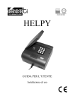
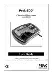
1
GB40-4
Peak Atlas LCR
Passive Component Analyser
Model LCR40
User Guide
© Peak Electronic Design Limited 2002/2009
In the interests of development, information in this guide is subject to change without notice - E&OE
electronic design ltd
Atlas LCR User Guide
January 2009 – Rev 4
Want to use it now?
We understand that you want to use your Atlas LCR
right now. The unit is ready to go and you should
have little need to refer to this user guide, but please
make sure that you read through pages 4-6!
Contents
Page
Introduction......................................................................... 3
Using your Atlas LCR......................................................... 5
Normal use
Probe compensation
Testing Inductors................................................................. 7
Testing Capacitors............................................................... 8
Testing Resistors ............................................................... 11
Low Resistance and Inductance
Taking care of your Atlas LCR ......................................... 12
Battery Replacement
Self Tests
Appendix A – Accessories ................................................ 14
Appendix B – Component Identification .......................... 15
Appendix C – Technical Specifications ............................ 17
Appendix D – Troubleshooting......................................... 18
Appendix E – Warranty Information................................. 19
Appendix F – Disposal Information.................................. 20
Page 2
Atlas LCR User Guide
January 2009 – Rev 4
Introduction
The Atlas LCR is an advanced instrument that greatly simplifies the testing of
passive components.
Traditional LCR bridges are inherently complex and very time consuming to
use.
The Atlas LCR does everything automatically, it tells you the component type
in addition to component value data.
What's more, the Atlas LCR automatically selects the best signal level and
frequency for the particular component under test.
The software is smart; all internal calculations are performed with floating
point maths. This means that precision isn't lost in the complex internal
calculations and all results are displayed in properly formatted and easy-toread engineering units, eg. 23.6pF.
Summary Features:
• Automatic component identification.
• Automatic test frequency selection (DC, 1kHz, 15kHz and
200kHz).
• Delayed or instant analysis (for hands free operation).
• Auto power-off.
• Probe and test lead compensation.
• Interchangeable probe sets.
• Automatic ranging and scaling.
• 1% basic accuracy for resistors.
• 1.5% basic accuracy for inductors and capacitors.
Page 3
Atlas LCR User Guide
January 2009 – Rev 4
Important Notices
WARNING:
This instrument must NEVER be connected to powered
equipment/components or equipment/components with
any stored energy (e.g. charged capacitors).
Failure to comply with this warning may result in personal
injury, damage to the equipment under test, damage to the
Atlas LCR and invalidation of the manufacturer's
warranty. Non-destructive overload situations are logged
in the non-volatile memory within the Atlas LCR.
“Analysis of discrete, unconnected components is
recommended.”
The Atlas LCR is designed to provide accurate and
reliable information for the majority of supported component
types (inductors, capacitors and resistors) as described in the
technical specifications. Testing of other component types or
component networks may give erroneous and misleading
results.
Page 4
Atlas LCR User Guide
January 2009 – Rev 4
Using your Atlas LCR
Normal Use
The Atlas LCR performs its component analysis before
the results are displayed. Therefore, once the analysis has
completed, the probes can be disconnected from the component.
Analysis itself only takes a few seconds and you can choose to
start the analysis after a 5 second delay or immediately.
Delayed Analysis: If you press the ontest button the unit will power-up (if it's
not already on!) and then delay for 5
seconds before analysis of your
component starts.
Analysis starts
in 5 seconds...
seconds...
This can be particularly useful if you need time to use both hands to apply the
test probes to the component while the analysis takes place.
Instant Analysis: You can skip the 5
second delay by pressing the on-test
button again. The analysis will then start
immediately.
Analysing...
Scrolling through the results: Results are displayed a screen at a time, simply
press the scroll-off button to see each screen when you're ready.
If you reach the last screen of results, pressing scroll-off will take you to the
first results screen again. Remember, you can take your time; and you don't
need to keep the component connected.
Starting again: The component analysis can be started again at any time by
pressing on-test.
Switching off: The unit will automatically switch off after about 20 seconds
following the last keypress. If you wish, you may manually switch off by
holding down the scroll-off button for about 1 second.
Page 5
Atlas LCR User Guide
January 2009 – Rev 4
Probe Compensation
If you change the probes on your Atlas LCR, it is good practice to run through
the short compensation procedure. This ensures that the probes' own
inductance, capacitance and resistance is automatically taken into account for
subsequent measurements.
Before you start the compensation procedure, attach a
small length of tinned copper wire between the two test
probes. Now let the leads rest on a non-conductive
surface, try not to touch them during the compensation
procedure.
Now press and hold on-test until the
following is displayed:
After a short delay, the unit will prompt
you to short the probes together. As you
have already shorted the probes with the
piece of wire, the Atlas LCR will then
ask you to open the probes.
Probe
Compensation
Please short
the probes
Now open
the probes
Now simultaneously unclip the both
probes from the small length of wire and let the leads rest without touching
them.
If this procedure has been successful, the unit will display “OK” and then
switch off.
At this point the parasitic and stray characteristics associated with the test
leads (and indeed the Atlas LCR itself) will be stored in non-volatile memory.
All further tests will have these values subtracted from the measured values,
therefore displaying the characteristics of the component alone.
Please note that probe compensation is particularly important when
analysing low value inductors, capacitors and resistors.
Page 6
Atlas LCR User Guide
January 2009 – Rev 4
Testing Inductors
The Atlas LCR is designed to analyse most inductors, coils and
chokes.
Inductor test frequency: The test frequency that the Atlas LCR uses will be
automatically selected from 1kHz, 15kHz or 200kHz. The following table
shows the test frequencies used for various inductance ranges:
Inductance Range
Between 0µH and 0.3mH
Between 0.3mH and 4mH
Between 4mH and 10H
Test Frequency Used
200kHz
15kHz
1kHz
The inductance range for each test frequency shown in the table above is
approximate. Effects such as DC resistance, hysteresis and Q factor can
influence the frequency that the Atlas LCR selects for your particular
inductor.
Inductance range: Values ranging from about 1µH to 10H can be measured,
with a minimum resolution of 0.4µH. The DC resistance of the inductor is
measured from 0.5Ω to 1kΩ with a
minimum resolution of 0.3Ω.
Inductance
Inductor results: Following analysis,
the inductance is displayed.
Press scroll-off to display the
frequency at which the inductance was
measured.
Pressing the scroll-off button again will
display the inductor's DC resistance.
1.507mH
Test frequency
15kHz
DC Resistance
67.2 ohms
Inductance measured for some components can be dependant on the test
frequency used. The effect of frequency on inductance varies depending on
the type of windings and core utilised. Even air cored inductors can show
significant changes of measured inductance at different frequencies.
Page 7
Atlas LCR User Guide
January 2009 – Rev 4
Testing Capacitors
The Atlas LCR uses two different methods to analyse
capacitors, AC impedance analysis for low value capacitors
(less than about 1µF) and DC charge analysis for larger
capacitors (about 1µF to 10,000µF).
Capacitors (particularly electrolytics) can store enough charge that
may cause damage to the LCR.
An electrolytic capacitor can even develop it’s own stored charge that
may be sufficient to cause damage to the Atlas LCR even after it has
been temporarily discharged. This is a characteristic known as
“Soakage”.
It is vitally important that you ensure the capacitor is fully discharged
(ideally for several seconds) to minimise the possibility of damage to the
unit.
If you are unsure, measure the voltage across the capacitor using a
suitable volt meter before applying the capacitor to the Atlas LCR.
The unit will automatically identify the type of capacitor being tested and
apply the most appropriate test method.
The capacitance will always be displayed in the most suitable units. To
convert between the various units refer to the following table:
pF
(pico-Farads)
1
1000
1000,000
1000,000,000
nF
(nano-Farads)
0.001
1
1000
1000,000
µF
(micro-Farads)
0.000001
0.001
1
1000
Page 8
mF
(milli-Farads)
0.000000001
0.000001
0.001
1
Atlas LCR User Guide
January 2009 – Rev 4
Low Value Capacitors
There is a vast range of low value capacitors available. Types include ceramic,
polyester, polystyrene and mylar dielectric capacitors. Generally, low value
capacitors tend to be unpolarised. Minimum capacitance resolution is about
0.1pF.
Capacitor test frequency: The Atlas LCR uses a high purity sine wave signal
of 1kHz, 15kHz or 200kHz to analyse these types of capacitors. The
frequency is automatically selected to give the best possible measurement
resolution.
The following table shows the test frequencies used for various capacitance
ranges:
Capacitance Range
Between 0pF and 1nF
Between 1nF and 15nF
Between 15nF and 1µF
Above 1µF
Test Frequency Used
200kHz
15kHz
1kHz
DC
The capacitance ranges for each test frequency shown in the table above is
approximate. Effects such as leakage, dielectric dissipation and ESR can
influence the frequency that the Atlas LCR selects for your particular
capacitor.
Capacitor results: Following analysis of the capacitor, the capacitance value
is displayed first. Press the scroll-off button to display the frequency at
which the capacitance was measured.
Capacitance
48.3pF
Test frequency
200kHz
Page 9
Atlas LCR User Guide
January 2009 – Rev 4
Large Capacitors
Capacitors larger than about 1µF are treated differently,
instead of being tested with an AC signal, they are tested with
a DC signal. This is confirmed in the “Test frequency” screen.
Please be patient when testing large value capacitors, it may
take several seconds depending on the capacitance.
Capacitance
106.5uF
Test frequency
DC
For capacitance values of greater than 1000µF, the Atlas LCR will use the
units of mF (milli-Farads). Don’t confuse milli-Farads with micro-Farads,
1mF=1000µF.
Capacitors (particularly electrolytics) can store enough charge that
may cause damage to the LCR.
An electrolytic capacitor can even develop it’s own stored charge that
may be sufficient to cause damage to the Atlas LCR even after it has
been temporarily discharged. This is a characteristic known as
“Soakage”.
It is vitally important that you ensure the capacitor is fully discharged
(ideally for several seconds) to minimise the possibility of damage to the
unit.
If you are unsure, measure the voltage across the capacitor using a
suitable volt meter before applying the capacitor to the Atlas LCR.
Generally, tantalum capacitors and electrolytic capacitors are
polarised. The Atlas LCR, however, uses a maximum of 1V to test the
capacitor and so polarity of the Atlas LCR test probes is (usually)
unimportant.
Page 10
Atlas LCR User Guide
January 2009 – Rev 4
Testing Resistors
Resistance values ranging from 0.5Ω to 2MΩ can be
measured, with a minimum resolution of about 0.3Ω.
Resistance is measured using a DC signal with a peak voltage
of 1V (across an open circuit) and a peak current of about 3mA (through a
short circuit).
Resistor results: Following analysis, the
resistance value is displayed.
Resistance
332.2k
Low Resistance/Inductance
Low value inductors (<5µH) and low value resistors (<10Ω) are treated as a
special case by the Atlas LCR. This is because low value inductors and low
value resistors can exhibit very similar characteristics at the test frequencies
available from the Atlas LCR.
The following message is displayed:
Low Resistance
and Inductance
Inductance
Pressing the scroll-off button will
display the values of resistance and
inductance that the Atlas LCR has
measured.
Resistance
1.3 ohms
The test frequency displayed is the
frequency used for the measurement of
the inductance.
Inductance
0.6uH
Test frequency
200kHz
Please note that probe compensation is particularly important when
analysing low value inductors, capacitors and resistors.
Page 11
Atlas LCR User Guide
January 2009 – Rev 4
Taking care of your Atlas LCR
Battery Replacement
The Atlas LCR requires no special maintenance
although the battery should be replaced every 12
months to prevent leak damage.
* Low Battery *
If this message is displayed, the battery
should be replaced as soon as possible to
prevent malfunction or leak damage.
Although the unit may continue to operate following a low battery warning,
measurements may be adversely affected.
New batteries can be purchased from many retailers and directly from Peak
Electronic Design Ltd or an authorised agent.
Battery types: Suitable battery types include 23A, V23A, GP23A, MN21 or a
good quality 12V alkaline equivalent as used in many test instruments and
automotive remote key fobs.
Battery access: To replace the battery, unscrew the three screws to remove the
rear panel. Remove the old battery and insert a new one, taking care to
observe the correct polarity. Carefully replace the rear panel, do not overtighten the screws.
Peak Safe Battery Disposal Scheme: Please return your old analyser battery
to Peak Electronic Design Ltd for safe and environmentally responsible
disposal.
Page 12
Atlas LCR User Guide
January 2009 – Rev 4
Self Tests
Many internal functions are tested each time the unit is powered up. If any of
these self tests do not meet tight
performance limits, a message will be
Error 02
displayed similar to the following:
The unit will then switch off.
It is possible that a temporary condition caused the failure and restarting the
unit may clear the problem. If the fault persists please contact Peak Electronic
Design Ltd or an authorised agent with details of the error message for further
advice.
Please note that some internal tests cannot be performed if a low battery
warning has been displayed. This means that if there is an internal problem, a
low battery condition can prevent the error condition from being displayed. It
is therefore strongly recommended that a low battery is replaced as soon as a
“Low Battery” message is displayed.
Page 13
Atlas LCR User Guide
January 2009 – Rev 4
Appendix A – Accessories
A range of useful additions is available to enhance your Atlas LCR.
Carry Case
A specially designed case with custom made foam compartments and a smart
tough exterior is ideal for protecting your Atlas LCR and probes. There's even
space for a spare battery.
SMD Tweezer Probes
These tweezers are ideal for testing many types of surface mount device. The
tweezers can cope with package sizes of 0402, 0603, 0805, 1206, 1210 and
Case A/B/C/D.
Fitting is easy: the tweezers are terminated in the standard Atlas LCR probe
connectors.
Other Probe Accessories
Many different probe types are available, specially made for your Atlas LCR.
Contact Peak Electronic Design Ltd or an authorised agent for more details.
Page 14
Atlas LCR User Guide
January 2009 – Rev 4
Appendix B - Component Identification
It is important to appreciate that the Atlas LCR can only decide on the identity
of the component under test using results of the electrical tests that it performs
on the component.
The Atlas LCR determines the type of component under test according to the
following criteria:
Inductor and Resistor Detection
The Atlas LCR will distinguish between components that are largely inductive
or largely resistive according to the values of inductance and resistance that it
has measured. This is illustrated in the following graph.
For example, if the inductance of your component is measured at 100µH and
it has a DC resistance of 100Ω, then the Atlas LCR will tell you that you have
a resistor. If however the resistance was only 10Ω, then the Atlas LCR will
tell you that you have an inductor.
Note that any inductor with a DC resistance of more than 1000Ω will be
identified as a resistor.
Page 15
Atlas LCR User Guide
January 2009 – Rev 4
Capacitor Detection
The Atlas LCR will tell you that you have a capacitor if the following criteria
are satisfied:
1. If the measured DC resistance is higher than 10MΩ, even if the
measured capacitance is very low (such as open probes).
or
2. If the measured DC resistance is between 100kΩ and 10MΩ and
the measured capacitance is larger than 10pF.
or
3. If the measured DC resistance is between 1kΩ and 100kΩ and the
measured capacitance is larger than 100nF.
Resistor Detection
Measured characteristics that do not satisfy any of the above criteria (for
inductors or capacitors) will be displayed as a resistive element.
Page 16
Atlas LCR User Guide
January 2009 – Rev 4
Appendix C – Technical Specifications
Parameter
range
Resistance
resolution
accuracy
range
Capacitance
resolution
accuracy
range
Inductance
resolution
accuracy
Peak test voltage (across O/C)
Peak test current (thru S/C)
1kHz
Test frequency
14.925kHz
accuracy
200kHz
Sine purity
Operating temperature range
Battery operating voltage
Notes:
1.
2.
3.
4.
5.
6.
Min
Typ
Max
1Ω
2MΩ
0.3 Ω
0.6Ω
Typically ±1.0% ±1.2Ω
0.5pF
10,000µF
0.2pF
0.5pF
Typically ±1.5% ±1.0pF
1µH
10H
0.4µH
0.8µH
Typically ±1.5% ±1.6µH
-1.05V
+1.05V
-3.25mA
+3.25mA
-1.5%
±1%
+1.5%
-1.5%
±1%
+1.5%
-1.5%
±1%
+1.5%
rd
Typically -60dB 3 harmonic
10°C
40°C
8.5V
13V
Note
1,2,6
1,2,5
1,2,4
3
Within 12 months of factory calibration. Please contact us if you
require a full re-calibration and/or certification of traceable
calibration.
Specified at temperatures between 15°C and 30°C.
Subject to acceptable LCD visibility.
For inductances between 100µH and 100mH.
For capacitances between 200pF and 500nF.
For resistances between 10Ω and 1MΩ.
Page 17
Atlas LCR User Guide
January 2009 – Rev 4
Appendix D – Troubleshooting
Problem
Capacitance measured when
probes are open circuit is not
close to zero (±1.0pF).
Resistance and/or inductance
measured when probes are
short circuit is not close to
zero (±1.2Ω, ±1.6µH).
Measured value doesn’t
appear to be correct.
Measured values vary
slightly between tests.
Calibration date is
approaching or has past.
Probe has become detached.
Possible Solution
Perform a probe compensation.
Perform a probe compensation.
Ensure probes are well connected to the
component under test for the entire duration
of the analysis.
Ensure that nothing else is connected with
the component under test. Make sure that
you are not touching the connections.
The component value may be outside the
supported measurement range.
The component’s design frequency may not
correspond to the test frequencies used by
the Atlas LCR.
The displayed resolution is higher than the
measurement resolution to avoid rounding
errors. Small variations within the quoted
measurement resolutions are normal.
Don’t worry, the Atlas LCR will carry on
working after the “Calibration Due Date”
has past. The date is simply a
recommendation.
The probes simply fit to the test lead using
square-pin connectors, carefully push them
back together.
Page 18
Atlas LCR User Guide
January 2009 – Rev 4
Appendix E – Warranty Information
Peak Satisfaction Guarantee
If for any reason you are not completely satisfied with the Peak Atlas LCR
within 14 days of purchase you may return the unit to your distributor. You
will receive a refund covering the full purchase price if the unit is returned in
perfect condition.
Peak Warranty
The warranty is valid for 12 months from date of purchase. This warranty
covers the cost of repair or replacement due to defects in materials and/or
manufacturing faults.
The warranty does not cover malfunction or defects caused by:
a) Operation outside the scope of the user guide.
b) Unauthorised access or modification of the unit (except for battery
replacement).
c) Accidental physical damage or abuse.
The customer’s statutory rights are not affected by any of the above.
All claims must be accompanied by a proof of purchase.
Page 19
Atlas LCR User Guide
January 2009 – Rev 4
Appendix F – Disposal Information
WEEE (Waste of Electrical and Electronic Equipment),
Recycling of Electrical and Electronic Products
United Kingdom
In 2006 the European Union introduced regulations (WEEE) for the collection
and recycling of all waste electrical and electronic equipment. It is no longer
permissible to simply throw away electrical and electronic equipment. Instead,
these products must enter the recycling process.
Each individual EU member state has implemented the WEEE regulations
into national law in slightly different ways. Please follow your national law
when you want to dispose of any electrical or electronic products.
More details can be obtained from your national WEEE recycling agency.
If in doubt, you may send your Peak Product to us for safe and
environmentally responsible disposal.
At Peak Electronic Design Ltd we are committed to continual product development and improvement.
The specifications of our products are therefore subject to change without notice.
© 2008 Peak Electronic Design Limited - E&OE
West Road House, West Road, Buxton, Derbyshire, SK17 6HF, UK.
www.peakelec.co.uk Tel. +44 (0) 1298 70012 Fax. +44 (0) 1298 70046
Page 20