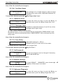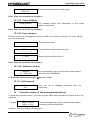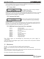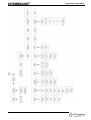
1
Operating Instructions
HV 1.1-HV 1.2
Incl. RS 485 - interface
English
771079202
210991-2 Manual HV1_1-1_2-V-EN
HV1.1-2-ENV
Operating Instruction
Index
1
IMPORTANT SAFETY INSTRUCTIONS .......................................................................................... 4
2
SYSTEM DESIGN ........................................................................................................................ 6
3
PRESSURE TANK ....................................................................................................................... 7
4
TRANSDUCER............................................................................................................................. 8
4.1
4.2
5
TECHNICAL DATA - FREQUENCY INVERTER AND GENERAL DATA............................................. 10
5.1
6
PRESSURE TRANSMITTER SERIES PA-21 R ..........................................................................................8
DIFFERENTIAL PRESSURE TRANSMITTER SERIES PD 39 M.......................................................................9
DIMENSIONS ................................................................................................................................11
HYDROVAR MOUNTING ........................................................................................................... 12
6.1 MOUNTING THE HYDROVAR ON THE PUMP .......................................................................................12
6.1.1 Included components...........................................................................................................12
6.1.2 Mechanical mounting ..........................................................................................................13
6.1.3 Mounting the thermistor .....................................................................................................16
6.1.4 Mounting of the pressure transducer..................................................................................17
6.2 ELECTRIC INSTALLATION AND WIRING ..................................................................................................18
6.2.1 Means of protection.............................................................................................................18
6.2.2 Wiring the Hydrovar to the motor........................................................................................18
6.2.3 Control.................................................................................................................................21
6.2.4 Terminals .............................................................................................................................21
6.3 FRONT PLATE ................................................................................................................................23
7
OPERATION WITHOUT EXTERNAL PROGRAMMING DEVICE...................................................... 24
8
POSSIBLE INDICATIONS OF THE LED ON THE HYDROVAR......................................................... 25
9
OPERATION IN THE MAIN MENU ............................................................................................. 26
10
CONNECTING THE EXTERNAL PROGRAMMING DEVICE TO THE HYDROVAR............................. 27
11
TYPICAL APPLICATIONS ........................................................................................................... 28
11.1 SETTING SINGLE PUMP CONSTANT PRESSURE .......................................................................................28
11.2 SINGLE PUMP - PUMP PROTECTION....................................................................................................29
11.3 SINGLE PUMP – SYSTEM CURVE COMPENSATION ..................................................................................31
11.4 ENTERING COMPENSATION VALUES ...................................................................................................32
MULTIPLE PUMP CONSTANT PRESSURE AND SYSTEM COMPENSATION ....................................................................34
12
SETTINGS AT THE INVERTERMENU........................................................................................... 39
13
SETTINGS AT THE SUBMENU-PARAMETER ............................................................................... 40
13.1 PRESSURE CHANGE .........................................................................................................................40
13.2 AUTO START .................................................................................................................................40
13.3 MODE.........................................................................................................................................40
13.4 CONTROL RESPONSE .......................................................................................................................41
13.4.1 Dimension unit ...................................................................................................................41
13.5 SUBMENU INVERTER .......................................................................................................................41
13.5.1 Maximum Frequency...........................................................................................................41
13.5.2 Minimum frequency............................................................................................................42
13.5.3 Boost ..................................................................................................................................42
13.5.4 Operation of the minimum frequency.................................................................................42
13.5.5 Delay time for Fmin.............................................................................................................42
13.6 SUBMENU CONTROLLER ..................................................................................................................42
www.hydrovar.com
2
Operating Instruction
13.6.1 Window - % ........................................................................................................................43
13.6.2 Ramp Hysteresis..................................................................................................................43
13.6.3 Fast acceleration time .........................................................................................................43
13.6.4 Fast deceleration time.........................................................................................................43
13.6.5 Slow acceleration time........................................................................................................43
13.6.6 Slow deceleration time .......................................................................................................44
RAMP WINDOW ......................................................................................................................................44
13.6.7 Compensation Frequency....................................................................................................44
13.6.8 Lift-Intensity........................................................................................................................44
13.7 SUBMENU MULTICONTROLLER ..........................................................................................................45
13.7.1 Lift Value ............................................................................................................................45
13.7.2 Fall Value ............................................................................................................................45
13.7.3 Release – Follow up pump ..................................................................................................46
13.7.4 Switch Interval ....................................................................................................................46
13.8 SUBMENU RELAY ...........................................................................................................................47
13.8.1 Relay Configuration ............................................................................................................47
13.8.2 Start frequency of the slave pump ......................................................................................47
13.8.3 Stop frequency of the slave pump ......................................................................................47
13.9 SUBMENU SENSOR .........................................................................................................................47
13.9.1 Sensor – Adjust ...................................................................................................................48
13.9.2 SensorMax-Adjust ...............................................................................................................48
13.10 SUBMENU TEST-RUN ......................................................................................................................48
13.10.1 Start of manual test run....................................................................................................48
13.10.2 Sequence for automatic test run.......................................................................................48
13.10.3 Test Run: Frequency .........................................................................................................48
13.10.4 Test Run: Boost.................................................................................................................49
13.11 SUBMENU ERROR...........................................................................................................................49
13.11.1 Conveyor Limit..................................................................................................................49
13.11.2 Error Delay ........................................................................................................................49
13.12 SET PASSWORD .............................................................................................................................49
13.13 DEFAULT SETTINGS.........................................................................................................................49
13.14 SUBMENU DIAGNOSIS.....................................................................................................................49
13.14.1 Pump Runtime ..................................................................................................................50
13.14.2 Pump Address...................................................................................................................50
13.14.3 Error memory....................................................................................................................50
13.14.4 Software Version ..............................................................................................................50
13.15 SET PASSWORD .............................................................................................................................50
14
CONTROLLER MENU (OF THE PROGRAMMING DEVICE) ........................................................... 50
14.1 CONTROLLER MENU CONFIGURATION .................................................................................................51
14.1.1 Automatic connection to the programming device .............................................................51
14.1.2 Software Version of the programming device.....................................................................51
14.2 SUBMENU ADDRESS........................................................................................................................51
14.2.1 Change of pump address ....................................................................................................51
15
POSSIBLE ERROR MESSAGES ................................................................................................... 52
15.1
15.2
15.3
15.4
15.5
15.6
15.7
15.8
15.9
16
LOW WATER.................................................................................................................................52
OVERHEATING – MOTOR .................................................................................................................52
OVERVOLTAGE ..............................................................................................................................52
UNDERVOLTAGE ............................................................................................................................52
OVERLOAD ...................................................................................................................................52
OVERHEATING OF THE HEAT SINK .......................................................................................................52
SENSOR FAULT ..............................................................................................................................53
CONVEYOR LIMIT FAULT...................................................................................................................53
ADDITIONAL INTERNAL PROCESSOR ERROR MESSAGES: ...........................................................................53
MAINTENANCE ........................................................................................................................ 53
Follow the Pump Operating and Maintenance Instructions
We reserv the right to alter specifications
www.hydrovar.com
3
Operating Instruction
1
Important safety instructions
Read and follow the operating instructions
and safety instructions carefully before
starting operations! All modifications must be
done by qualified technicians!
Warns that failure to observe the precaution may cause electric shock.
Warns that failure to observe the precaution may cause personal injury or
damage to property.
In addition to the instructions contained in these operating instructions please pay
attention to universal safety and accident prevention regulations.
The HYDROVAR drive head must be disconnected from the power supply before any work
can be carried out in the electrical or mechanical part of the system.
Installation, maintenance and repair work may only be carried out by trained, skilled and
qualified personnel.
Unauthorised modifications or changes to the system make all guarantees null and void.
When in operation the motor can be stopped by remote control, whereby the drive head
and the motor remain under voltage. For safety reasons, the unit must be disconnected from
the power supply when carrying out work on the machinery as locking out the equipment
by switching off the release mechanism or set value cannot prevent accidental starting of
the motor.
When the drive head is connected to power supply, the components of the
power unit as well as certain components of the master control unit are also
connected to the power supply.
Touching these components seriously endangers life !
Before removing the frequency inverter cover the system must be
disconnected from the power supply. After switching off the power supply
wait at least 5 minutes before starting work on or in the HYDROVAR drive
head (the capacitors in the intermediate circuit have to be discharged by the
installed discharge resistors first).
www.hydrovar.com
4
Operating Instruction
Voltages of up to 400 volts are possible (if there are faults it can be higher).
All work carried out when the frequency inverter is open may only be
performed by qualified authorised staff.
Furthermore, care must be taken not to short circuit the neighbouring
components when connecting the external control wires and that open
cable ends which are not in use are insulated.
The HYDROVAR drive head contains electronic safety devices which switch off
the control element in the event of faults, whereby the motor has zero current
but remains energised and comes to a halt. The motor can also be halted by
mechanical blocking. If it is switched off electronically the motor is
disconnected from the mains voltage through the electronics of the frequency
converter but is not potential-free in the circuit.
In addition voltage fluctuations, especially power failures can cause the
system to switch off itself.
Repair of faults can cause the motor to start up again.
The system may only be put into operation when it has been earthened. In addition,
equipotential bonding of all pipes must be ensured.
The operating instructions must be read, understood and followed by the operating
personnel. We point out that we accept no liability for damage and operating disorders
which are the result of non-compliance with the operating instructions.
Please
note:
High voltage tests of the inverter or the motor may damage the
electronic components! Hence bridge before the in- and outgoing
terminals L -N -- U- V-W.
To avoid incorrect metering by capacitors incorporated in the
electronic part isolate the motor from the Hydrovar Drive head.
www.hydrovar.com
5
Operating Instruction
2
System Design
The following diagrams show typical single pump and multi-pump systems using the
Hydrovar control unit. Connection can be made directly to a water supply or water can be
drawn from a break tank or well. In the case of break tanks and wells, level switches, should
be used to shut down the pumps when water is low. In the direct connection, a pressure
switch on the suction side should be used.
(1) pump with drive head
(2) diaphragm tank
(3) distribution panel
(4) gate valves
(5) non return valves
(8) incoming pressure switch
(9) pressure gauges
(14) pressure transmitter
Single pump layout
Multiple pump Layout
www.hydrovar.com
6
Operating Instruction
3
Pressure tank
A diaphragm pressure tank is used on the discharge side of the pump or pumps to maintain
pressure in the line when there is no demand. This will keep the pumps from continuing to
run. With the Hydrovar control unit, it is not necessary to have a large tank for supply
purposes. In selecting a tank, make sure it can withstand systems pressure. The tank should
have a capacity of more than 10% of the maximum system flow rate l/min of one pump.
Ask of required certificates needed for your country!
Precharge the tank to the following:
Solldruck / required pressure [bar]
Before checking the precharge pressure, take care, that the tank, is
pressureless (no water inside).
www.hydrovar.com
7
Operating Instruction
4
Transducer
4.1
Pressure Transmitter
Series PA-22 S
The sensor of this transmitter is a piezoresistive silicon pressure sensor, mounted on a
tape (TAP) freely floating in an oil chamber. The pressure is transferred to the sensor by a
separate steel diaphragm in the oil chamber.
Specifications
Range (FS):
Max. pressure-Pmax:
Class of protection :
10 bar 25 bar (other ranges upon request)
20 bar 50 bar
IP 67
Output signal:
0,5 – 4,5 V DC
Supply:
5 VDC +/- 5 %
Operating temperature: -10...+80°C compensated (max. –40...135 °C)
Storage Temperature:
-40...+135°C
Cable length:
1,2 m
connections:
white = analogue output signal (+ Out) (1)
green = Ground (GND) (2)
brown = supply voltage (+ VCC) (3)
Materials:
Body:
1.4435
diaphragm: 1.4435
plug / cable
Pressure transmitter
gasket
gasket Viton®
Measures in mm
www.hydrovar.com
8
Operating Instruction
4.2
Differential Pressure Transmitter
Series PD 39 M
The sensors of this differential pressure transmitter are two piezoresistive silicon pressure
sensors, mounted on a tape (TAP) freely floating in an oil chamber. The pressure is
transferred to the sensor by a separate steel diaphragm in the oil chamber.
Specifications
Range (FS):
Over-pressure- Pmax:
Class of protection :
4 bar
16 bar
IP 65
differential
single-sided
Output Signal:
Supply:
Load Resistance:
0,5 – 4,5 V DC (ratiometric)
5 VDC +/- 10 %
> 5 kΩ
Linearity::
Stability:
±0.20 % FS; max. ±0.5% FS
±0.1 % FS; max. ±0.2% FS
Operating temperature:
Storage Temperature:
-10...+80°C
-40...+80°C
Material: Body and diaphragm: 1.4435 Stainless steel
Screw joint and cover: Steel electroplated for Emetorpipe d=8mm
Plug: mPm 193
P-
P+
Incl. 2m cable:
Out (white)
+ Vcc (brown)
GND (green)
Screen
www.hydrovar.com
9
Operating Instruction
5
Technical Data - Frequency Inverter And General Data
HYDROVAR
Type
Rated
output
1,1 kW
1,5 kW
2,2 kW
HV 1.1
HV 1.15
HV 1.2
Output voltage:
Min. frequency:
Electrical efficiency:
Hydrovar output to
the Motor
Voltage
Max.
current
3x 230V
4,8 A
3x 230V
7,0 A
3x 230V
10,0 A
Supply Voltage (Uin)
Mains frequency
48-62 Hz
1x 220-240 V ±15%
1x 220-240 V ±15%
1x 220-240 V ±15%
Prefuse
min.
10 Ampere
10 Ampere
16 Ampere
3x 0...Uin VAC / 0-70 Hz
(depends on the input voltage)
0 – max. frequency
> 95%
Protection against: Short circuit, over- and undervoltage, overheating of the electronics
(overload) and additional external protective functions via PTC
(motor temperature) and low water switch.
A mains filter is fitted to ensure interference immunity.
The HV Series frequency converter complies with the general EMC provisions and has
been tested according to the following standards:
·
·
·
Disturbance voltage:
EMC – Immunity:
Electrostatic discharge:
EN 55011
EN 61000-4-3 and ENV 50204
EN 61000-4-2
Ambient temperature:
Storage temperature:
Humidity:
5° C ... + 40°C
-25° C ... + 55° C (+70°C during max. 24 hours.)
rH max. 50% at 40°C, unlimited
rH max. 90% at 20°C, max. 30 days per year
Condensation not permitted !
Air pollution:
The air may contain dry dust as found in workshops where
there is no excessive quantity of dust due to machines.
Excessive amounts of dust, acids, corrosive gases, salts etc.
are not permitted
max. 1000m above sea level
At higher altitudes the max. available power has to be
reduced. Please ask the manufacturer for further details.
IP55
Altitude::
Class of protection :
www.hydrovar.com
10
Operating Instruction
5.1
Dimensions
HV1.1:
closing cap
Æ12
Type:
Weight
[Kg]
HV 1.1
HV 1.15
HV 1.2
2,00
4,70
4,70
cable gland
Æ7
HV1.15,1.2:
closing cap
cable entries
www.hydrovar.com
11
Operating Instruction
6
HYDROVAR mounting
6.1
Mounting the HYDROVAR on the pump
6.1.1 Included components
Variant for HV1.1:
thermistor
mounting and distance ring
screw
washer
Variant for HV1.15-1.2:
thermistor
screw M5x50
cable gland
www.hydrovar.com
mounting clamp
12
cable gland
Operating Instruction
6.1.2 Mechanical mounting
Variant for HV1.1
Hydrovar
1. Remove the motor fan cover from
your 3-phase motor by removing the
mounting screws.
2. Put the mounting and distance ring
(1) between the fan cover and the
Hydrovar and fix them together with
the screw (3) by using the included
washer(2).
(1) mounting
and distance
ring
3. Use the fan cover screws to mount
the fan cover/Hydrovar combination
to the motor
motor fan
cover
(2) washer
(3) screw
Note:
Don’t forget the washer between the screw and the motor fan cover!
www.hydrovar.com
13
Operating Instruction
Variant for HV1.15-1.2:
Don’t forget the gaskets for the 3 screws .
Ensure that there is no water on the unit
before you open the cover.
Gasket
4 screw
M5x50
Center bit
4 mounting clamps
Connection
Motor conduit box
Thermistor
Transducer
www.hydrovar.com
14
Mounting:
u Remove the 3 screws from the
Hydrovar cover.
u Place the centre bit in the
Hydrovar fan cover.
u Place the Hydrovar fan cover on
the motor .
u Hang the 4 clamps by the
Motor fan cover and mounted
with the 4 screws.
u Mounted the cover with the
3 screws.
Operating Instruction
Mounting ring
If you use a motor with plastic fan cover, you must use
a mounting ring.
www.hydrovar.com
15
Operating Instruction
6.1.3 Mounting the thermistor
Variant A:
motor
thermistor
terminal block
rubber gasket
cover of the
conduit box
Variant B:
Thermistor
1. Open the cover of the conduit box and remove also the terminal block inside.
2. Fix the thermistor (Variant A or B)
3. Electrical connection of the motor cables see chapter 6.2.
www.hydrovar.com
16
Operating Instruction
6.1.4 Mounting of the pressure transducer
In the delivery of the pressure transducer there are included:
plug / cable
Pressure transmitter
gasket
gasket Viton®
1. The transducer has an mechanical connection of G ¼”.
2. Electrical connection to the Hydrovar see chapter (6.2)
www.hydrovar.com
17
Operating Instruction
6.2
Electric installation and wiring
Note:
All installations and maintenance MUST be performed by trained
and qualified personal with proper tools!!
Warning:
In case of a failure, disconnect and lockout electrical
power and wait five minutes for capacitor discharge
before servicing the Hydrovar.
6.2.1 Means of protection
Ask your power supply company which means of protection are required.
Applicable:
AC and DC current-operated circuit breaker (FI), TN systems, protective
circuits.
When using a FI protection switch, make sure that it also releases in the event of
a DC fault, use for each Hydrovar a separate FI-switch!
6.2.2 Wiring the Hydrovar to the motor
Remove the 3 screws holding the top of the Hydrovar. Carefully lift the top, loose the earth
screw and put the Hydrovar cover aside.
Now you can see the 2 main parts
(1)
control card with all terminals for the control signals and the RS485 interface
(2)
main card with all power components and terminals for power supply and motor
www.hydrovar.com
18
Operating Instruction
6.2.2.1 Main part overview
HV1.1:
control card (1)
main supply
connections
Motor
connections
main board
(2)
Cable introduction
for motor cable
(at least 11,5mm)
Cable gland (for
power supply
5-10mm)
Cable introduction for control
cable (at least 5mm)
HV1.15, 1.2:
control card (1)
main board (2)
motor
connections
main supply
connections
cable introduction for
control cable
www.hydrovar.com
19
Operating Instruction
6.2.2.2 Connecting the power cables
a) motor cable:
Locate the motor connections, labeled U, V, W inside the Hydrovar. Connect wires to the
terminals and rout the cable through the cable gland.
You must take a motor cable at least Ø 11.5mm if you want protection IP55. (only HV1.1)
The earth-wire of the cable has to be fixed with the screws with the earth-symbol to the
cooling body of the Hydrovar.
Connections in the conduit box
The connection of the motor cable depends on the type of the motor and can be done in
star or delta connection:
(you have to use the connection for a motor voltage of 3x230V shown on the motor label)
Star-connection
Delta-connection
b) supply cable
The main power cable is connected to the terminals labelled L1, N for the 230 VAC, single
phase input (shown in the diagram 6.2.2.1).
www.hydrovar.com
20
Operating Instruction
6.2.3 Control
By using the HYDROVAR drive head for constant pressure control, together with a
pressure or differential pressure transmitter, or, if required, according to external
manual control by reference of 0,5-4,5VDC, this external signal has to be
connected to the terminals X2/1, X2/2 and X2/3 of the control terminals.
terminals of the
RS485 interface
control terminals
HV1.1
HV1.15, 1.2
6.2.4 Terminals
All externally used cables have to be shielded. Do not connect the mass of the electronic
components to other higher potentials.
All electronic ground and GND of the RS 485-interface are internally connected.
For external off/on and low water, switch contacts suitable for <10 V are necessary.
The control cable must be at least Ø 5mm.
If unshielded control cables are used, signal interference may occur and interfere with the
function of the inverter.
When connecting together the variable speed pumps (max. 4 pumps) via the interface RS
485, the terminals X3/1 and X3/2 and X3/3 are to be connected in parallel by means of a
shielded cable to every HYDROVAR drive head and programmed accordingly
www.hydrovar.com
21
Operating Instruction
Control-Terminals:
Thermistor
External release Ri 10kOhm, 5VDC (use gold
plated contact)
Power supply for external control 5VDC
0,5-4,5 VDC
Ground (not earthened)
www.hydrovar.com
22
Operating Instruction
6.3
Front plate
HV 1.1-1.2:
www.hydrovar.com
indication LED
23
push buttons
Operating Instruction
7
Operation without external programming device
Warning:
Before you start the system, the pump must be filled and all wiring and
piping have to be done!
Note: The Hydrovar is delivered with these settings as standard!
¨
¨
Change Pressure:
Auto Start:
enabled
enabled
Other possibilities to use the push buttons of the Hydrovar:
The Pump could be
STARTED with the
button (if Autostart is disabled, the pump can be started by
pressing the
button and then the
button at the first startup or after a
power supply failure) or
STOPPED with the
button.
Both buttons are on the front plate of the Hydrovar
·
Change pressure without programming device:
To change the pressure without the external programming device you have to
follow:
on the front plate of the Hydrovar
1.
Start the pump with the push button
2.
Then press the
3.
The colour of the LED changes to orange
4.
Now you can change the pressure with the
and buttons.
The only way to check the set pressure is given by a pressure gauge.
5.
If there is no action for more than 5 sec., the HYDROVAR returns to normal
operation automatically, and the new required pressure is saved.
www.hydrovar.com
and
buttons together for longer than 3 sec.
24
Operating Instruction
8
Possible indications of the LED on the HYDROVAR
.) Green shining
Þ Motor stopped
(via external stop with terminals X2/4; X2/5
or the unit is stopped with the button on the front plate)
.) Green slow flashing
Þ Inverter is active, but the motor has stopped
.) Green fast flashing
Þ Motor runs
.) Orange shining
Þ required pressure can be changed without the
programming device with the buttons and ,
or the external programming device is connected and the
pump is stopped with the button on the Hydrovar or
with the external release input (terminals X2/4 and X2/5).
.) Orange slow flashing Þconnected remote control and the inverter is released,
but the pump is not running (because of the required
pressure is reached).
.) Orange fast flashing
Þconnected external programming device and the pump is
running.
.) Red shining
Þ error signalling (type of the Error is shown on the display
of the external programming device)
.) Red flashing
Þ signalling of a fatal error (HYDROVAR has to be cut from
the power supply!)
www.hydrovar.com
25
Operating Instruction
9
Operation in the main menu
Menu overview
www.hydrovar.com
26
Operating Instruction
General for working with the external programming device:
With ç and è you can select the different parameters in the menu.
To enter a submenu, press the ê button. To leave the submenu, you have to press the
buttons ç or è for longer than 3 sec.
With é or ê you can change the parameters.
Each change in the settings is saved after leaving this parameter with the buttons
ç or è.
When you have changed a parameter and you leave it, the LCD shows you the following
message
SAVE
PARAMETER
10
for about 2 sec.
Connecting the external programming device to the HYDROVAR
After connection of the HYDROVAR – head to the power supply and plug in of the
external programming device, there can be shown two different messages:
1. If the AUTOCONNECTION is disabled (standard) you reach:
Address 01
Lost
This message is shown, when the Remote Control is
new connected
At this time the Hydrovar searches for an available address
If address 01 is available, the display changes to
Address 01
Detected
The actual pump-address is shown
Statusinformations by systems with activated Multicontroller:
P1: Masterpump
P2: Slavepump
P3: Slavepump
P4: Slavepump
P.: Follownumber is not useful
Hold:
pump stops through the pressure transmitter
Run:
pump runs
Stop:
pump stops through the leadpump
Disabled: pump stops through the stopbutton or the terminal block
Error:
pump stops through an error
ê Follow pump stopped
é Regulator from the follow pump is release
Pump don’t work at the follow pump
www.hydrovar.com
27
Operating Instruction
If the actual pump address 01 is not available the display does not change and you
will see again
Address 01
Lost
Then you could change the address with é and ê
and confirm the selected address with è.
Press è on the controller and you enter the INVERTERMENU
2. If the AUTOCONNECTION is enabled, following message is shown:
SCAN
CONNECTION
This message is shown during the connecting, when
AUTOCONNECTING is enabled
In this time the Hydrovar searches for the given or entered address!
Then the display changes to the 1st display
PRESS X.X bar
SPEED X.X Hz
11
The actual input value [bar] and the actual
output frequency [Hz] are displayed.
Typical applications
11.1 Setting Single Pump Constant Pressure
At the first startup, “Change Pressure” and “Autostart” of the external programming unit are
enabled. After connecting, on the display of the programming unit there is shown
Scan
Connection
This message is shown when the external
programming device is set up to the Hydrovar
and scanning a valid pump address.
After a few seconds, the display changes automatically to the 1st display
Press x.x bar
Speed x.x Hz
This window shows the actual values of the
Hydrovar (a required pressure of 3,5 bar is
previously set)
Press è on the controller to change to
Pressure
xx.x bar
To select required pressure use the
buttons é and ê.
After changing of the value, you have to confirm with the è-button. Then you will get the
message “SAVE PARAMETER” for a short time, when the new setting is saved!
After changing of the value, you have to confirm with the è-button.
Then press ç on the controller to change back to the 1st display
Press x.x bar
Speed x.x Hz
www.hydrovar.com
28
Operating Instruction
11.2 Single Pump - Pump Protection
www.hydrovar.com
29
Operating Instruction
Note:
Low/no suction depends on the installation of a suction line pressure switch, or float switch
for a tank. This is connected to the Hydrovar as described earlier in the Electrical Installation
section.
The cut off setting for this switch should be the maximum NPSH required by the pump.
To set run out protection:
Warning:
Run out protection is available for one pump systems and multiple pump systems with a
common suction pipe. In multiple pump systems with separate suction pipes, you can not
avoid dry running by measuring the system pressure, because the pressure is produced from
another pump in the system.
From the 1st display, press the è button twice, until you
reach
SUBMENU
PARAMETER
Then press the ê button and the display will change to
PASSWORD
0000
Password:
The Password protection prevents untrained personal from accidentally changing the base
setting
Press the é button until you reach the number 0066
PASSWORD
0066
Press the è button repeatedly until you reach
SUBMENU
ERROR
Press the ê button to enter the submenu and change to
CONVEYOR LIMIT
0,0 bar
CONVEYOR LIMIT
“0.0 bar” means disabled conveyor limit.
An adjusted value >0 has to be reached till the programmed “ERROR DELAY”-time.
Doesn’t this value be reached the failure “CONVEYOR CONTROL ERROR” will be indicated
and the pump stops.
By pressing the é and ê button, enter the pressure setting
CONVEYOR LIMIT
(bar) at which you want the pump to shutoff.
0 bar
Typically a setting of about 1 bar less than the standard pressure setting would be entered
After changing of the value, you have to confirm with the è button.
Then you will get the message “SAVE PARAMETER” for a short time, when the new setting is
saved!
Press the è button to change to
www.hydrovar.com
ERROR DELAY
10 s
30
Operating Instruction
ERROR DELAY:
Adjustable between 0...100 sec.
Delayed switch-off in the event of low water, terminal X2/6-X2/7) and also for the conveyor
limit.
By pressing the é and ê button, you will be entering the
ERROR DELAY
amount of time (sec) that the pump will run at the
10 s
programmed conveyor limit before it automatically shuts off.
After changing of the value, you have to confirm with the è button. Then you will get the
message “SAVE PARAMETER” for a short time, when the new setting is saved!
Hold the è button down for 3 seconds and you will be
returned to:
Hold the è button down again for 3 seconds to return to
the 1st display
SUBMENU
ERROR
PRESSURE x.x bar
SPEED xx Hz
11.3 Single Pump – System Curve Compensation
The Hydrovar can automatically compensate
for system friction losses due to increased
flow. Tables are available in most pump
catalogues indication the amount of friction
loss that can be expected in various sizes of
pumps at different flow rates. Use these
tables to determine the friction loss for the
pipe size you are using at maximum flow
rate.
This Diagram shows a typical system curve. The system pressure set point is shown at shutoff
and pressure increase is shown for increasing flow.
Calculate the pressure required to overcome friction loss at maximum flow.
www.hydrovar.com
31
Operating Instruction
11.4 Entering Compensation Values
www.hydrovar.com
32
Operating Instruction
Instructions:
From the 1st display, press the è button twice, until you
reach
SUBMENU
PARAMETER
Then press the ê button and the display will change to
PASSWORD
0000
Password:
The Password protection prevents untrained personal from accidentally changing the base
setting
Press the é button until you reach the number 0066
Press the è button repeatedly until you reach
Press the ê button to enter the submenu and change to
PASSWORD
0066
SUBMENU
CONTROLLER
WINDOW
5,0 %
Now press the è button until you reach the parameter “LIFT
LIFT FREQUENCY
FREQUENCY”
30 Hz
LIFT FREQUENCY:
This indicates the frequency at which the increase of the set pressure should begin.
It should be the speed at which the pump works at the set pressure and at delivery rate of 0
m³/h. On a 50 Hz system, there is virtually no flow below about 30 Hz, on a 60 Hz system
about 40Hz.
Press the é and ê button until you reach desired frequency.
LIFT FREQUENCY
30 Hz
After changing of the value, you have to confirm with the è button.
Then you will get the message “SAVE PARAMETER” for a short time, when the new setting is
saved!
Now press the è button to change to
LIFT INTENSITY
0,0 bar
LIFT INTENSITY:
This value states, how much the required value should be continually increased, till the
maximum speed (maximum volume) is reached.
Press the é and ê button until you reach desired value
LIFT INTENSITY
0,0 bar
After changing of the value, you have to confirm with the è button. Then you will get the
message “SAVE PARAMETER” for a short time, when the new setting is saved!
Hold the è button down for 3 seconds to return to:
SUBMENU
CONTROLLER
Hold the è button down again for 3 seconds to return to
the 1st display
www.hydrovar.com
33
PRESSURE x.x bar
SPEED xx Hz
Operating Instruction
11.5 Multiple pump constant pressure and system compensation
www.hydrovar.com
34
Operating Instruction
When two, three or four Hydrovar speed controlled pumps are connected together in a
system via the RS485-interface, they can be programmed to work together to maintain
system pressure up to the maximum flow rate of all the pumps combined.
As the first pump reaches its maximum speed and flow, the second pump will automatically
turn on (and so on). In addition, the sequence of the pump that will run first (lead pump)
can be automatically varied to reduce premature wear on any one pump in the system.
Instructions:
!! Refer to chapter 11.1 (setting single pump constant pressure).
Follow these instructions for setting the required pressure and then continue
with the following steps.
From the 1st display, press the è button twice, until you
reach
SUBMENU
PARAMETER
Then press the ê button and the display will change to
PASSWORD
0000
Password:
The Password protection prevents untrained personal from accidentally changing the base
setting
Press the é button until you reach the number 0066
Press the è button repeatedly until you reach
Press the ê button to enter the submenu and change to
PASSWORD
0066
SUBMENU
MULTICONTROLLER
ACTUAL VALUE INCREASE
0.15 bar
ACTUAL PRESSURE INCREASE (= Lift value):
This value, together with the fall value (ACTUAL VALUE DECREASE) determines the increase
of the required value after starting of the following pumps (see attached application
example on next page)
www.hydrovar.com
35
Operating Instruction
Generally a slight pressure drop is allowed on the first pump before the next is
started. This allows for brief systems fluctuations without pump cycling. Once the
next pump starts, however, you will want the system to resume its normal set
pressure.
To do this, enter the amount of pressure drop
you will allow before the next pump starts
(=value of parameter ACTUAL VALUE
DECREASE). The diagram shows the pressure
drop and increase.
To increase the pressure even more to
compensate for system loss at higher flows,
enter the total of the system drop allowed
before next pump starts and the increased
pressure (ACTUAL VALUE INCREASE) desired.
For example, if the pressure drop allow 0,35 bar before the next pump starts, and the
increased pressure needed to compensate for system losses is 0,2 bar, you would
enter 0,35 + 0,20 = 0,55 bar (= calculated value of the parameter ACTUAL VALUE
INCREASE) to compensate for both system pressure drop and compensation
requirements.
Application example:
1) Pump 1 reaches the speed of ENABLE SEQ: CONTROL
2) Pressure falls and reaches the start-value of the 2nd pump
(= REQUIRED VALUE – ACTUAL VALUE DECREASE)
3) Pump 2 is switched on automatically
4) The required value is calculated new, after the start of the 2nd pump in the
following way!
New required value = REQUIRED VALUE – ACTUAL VALUE DECREASE + ACTUAL
VALUE INCREASE
Generally:
k ... Number of active pumps
P = Pset + (k-1)*[lift value – fall value]
· Lift value = Fall value Þ Pressure constant when pumps switch on
· Lift value > Fall value Þ Pressure rises when lag-pump switches on
· Lift value < Fall value Þ Pressure falls when lag-pump switches on
Note:
This value is cumulative. An extra 0,2 bar will be added to the total system pressure with
each additional pump which turns on. For example, if the initial system pressure was 3,5 bar,
pump two would create 3,7 bar, pump three would create 3,9 bar, and pump four would
create 4,1 bar system pressure.
www.hydrovar.com
36
Operating Instruction
Enter the required value by pressing the é and ê button
ACTUAL VALUE INCREASE
0,15 bar
After changing of the value, you have to confirm with the è button.
Then you will get the message “SAVE PARAMETER” for a short time, when the new setting is
saved!
Press the è button to change to
ACTUAL VALUE DECREASE
0,15 bar
ACTUAL PRESSURE DECREASE (= Fall value):
This value determines amount of pressure drop you will allow before the next pump starts.
(see application example on previous page)
Enter the required value by pressing the é and ê button
ACTUAL VALUE DECREASE
0,15 bar
After changing of the value, you have to confirm with the è button.
Then you will get the message “SAVE PARAMETER” for a short time, when the new setting is
saved!
Press the è button to change to
ENABLE SEQ. CONTROL
48 Hz
ENABLE SEQUENCE CONTROL:
The follow-up pump only starts, when the start-value is reached and the lead pump has
reached the programmed release-frequency. (Adjustable from 0.0 Hz to 70 Hz). Normally
this start frequency is set 1 to 2Hz lower than the MAX. FREQUENCY
If you don’t want to start a following pump this value has to be set higher than the MAX.
FREQUENCY. (see application example on previous page)
Enter the required value by pressing the é and ê button
ENABLE SEQ. CONTROL
49 Hz
After changing of the value, you have to confirm with the è button.
Then you will get the message “SAVE PARAMETER” for a short time, when the new setting is
saved!
Press the è button to change to
SWITCH INTERVAL
24 HOURS
SWITCH INTERVAL
This time determines the interval of the changeover of the master pump in order to achieve
even operating hours of all pumps in the system. Adjustable between 0 and 250 hours
Enter the required value by pressing the é and ê button
www.hydrovar.com
37
SWITCH INTERVAL
24 HOURS
Operating Instruction
After changing of the value, you have to confirm with the è button.
Then you will get the message “SAVE PARAMETER” for a short time, when the new setting is
saved!
Use the settings of this submenu (lift value, fall value, enable sequence control and
switch interval) for each pump in the Hydrovar system
Hold the è button down for 3 seconds to return to:
Hold the è button down again for 3 seconds to return to
the 1st display
SUBMENU
CONTROLLER
PRESSURE x.x bar
SPEED xx Hz
If you set the addresses in a multiple pump system the first time, connect only the
Hydrovar unit where you want to set the address to power supply otherwise all
Hydrovars in the system connected over the RS485-interface will change their
address, too
In the following section you will give the pump an address number. Generally, the first
programmed pump will be number 1, the second will be number 2, and so on. The purpose
of this is to help the Hydrovar sequence the start and stop activity of the pumps in the
system including the selection of the lead and lag pumps.
From the 1st display, hold the è button for longer than 3
sec. to get the display, where the actual address is shown
or
When there is no active address, there is shown
Then press the ç button twice to change to
Press the ê button to enter the submenu and change to
Address 01
Detected
Address 01
LOST
Submenu
Address
Address Change
00 --> 00 *
Addresses from 01 to 04 and also 00 can be set in this parameter. To change the address
it is not necessary to cut the interface connection to other HYDROVARS.
On the left side there is shown the address of the HYDROVAR, which you are actually
speaking (select the address by using the buttons é or ê). On the right side, then you can
give the HYDROVAR a new address also with the buttons é and ê. You only can give an
address, which is not used in the pump group!
To change between left and right side, press buttonç or è. The star shows the actual
used side.
To save the new selected address press both buttons (ç and è) together for 2 sec. If it
was successfully you will see the same address on both sides.
www.hydrovar.com
38
Operating Instruction
Example:
To change the Hydrovar with address 01 to address 04:
press the ç button to change the * to the left side
Address Change
00* --> 00
Select the address of the Hydrovar, you want to change the
address with the é and ê button
Address Change
01* --> 00
press the è button to change the * to the right side
Address Change
01 --> 00*
Select the address you want to give this Hydrovar with the
é and ê button
Address Change
01 --> 04*
To confirm and save the new selected address press both buttons (çand è) together for
2 sec. If it was successfully you will see the same address on both sides.
Address Change
04 --> 04*
The definition of the address you have to do for each pump in the system.
Hold the è button down for 3 seconds to return to:
Hold the è button down again for 3 seconds to return to
the 1st display
12
SUBMENU
Address
PRESSURE x.x bar
SPEED xx Hz
Settings at the Invertermenu
1st display
PRESS X.X bar
SPEED X.X Hz
The actual input value [bar] and the actual
output frequency [Hz] are displayed.
Press è on the controller to change to
PRESSURE
XX.X bar
There you can set required pressure
with the buttons é and ê
Press è on the controller to change to
SUBMENU
PARAMETER
To enter the submenu “Parameter”,
press ê button
Press è on the controller to change to 1st display
www.hydrovar.com
39
Operating Instruction
13
Settings at the Submenu-Parameter
Warning: Before entering the secondary menu these instructions
must be read carefully to prevent incorrect settings which will
cause malfunction.
After entering the SUBMENU PARAMETER, the display
... will change to
PASSWORD
0000
Set Password 0066 by pressing é and ê
PASSWORD
0066
Note: The password must be entered at each entry
Confirm by pressing è and the first
parameter of the sub menu is shown
Change Pressure
Enabled
13.1 Pressure change
Change Pressure
You can decide between é (Enabled) or ê
Enabled
(Disabled)
If the pressure setting is enabled, you can change the required pressure on the
Hydrovarhead with decrease and increase (see chapter 7) without an external
programming device.
Press è on the controller to change to
13.2 Auto start
Auto Start
You can select between ê Disabled and é Enabled
Enabled
Autostart Enabled means, that the pump starts again automatically after an interruption
of the power supply (power failure).
If Autostart Disabled is set, the pump has to be restarted manually after a power failure,
by pressing
and .
Press è on the controller to change to
13.3 Mode
www.hydrovar.com
40
Operating Instruction
Mode
Select with buttons ê and é between:
Controller
Multicontroller Þ sequence control for max. 4 pumps
Controller Þ pressure control for a single pump If only one HYDROVAR-pump is in
operation, set Controller.
If more than one HYDROVAR-pumps are working together via the RS485-interface, the
Multicontroller must be selected.
Actuator Þ external frequency setting. The application Actuator is only used, if you
have an external controller and the HYDROVAR works like a standard frequency
converter (external frequency signal 0,5-4,5VDC to the terminals X2/1 and X2/2).
Press è on the controller to change to
13.4 Control Response
Regulation Mode
Normal
Normal: Speed is increased with falling actual value
Signals. (e.g.: Control at constant output pressure).
Inverse: Speed is reduced with falling actual value
signal, (e.g.: Control of constant suction pressure or at
constant level before the pump).
Press è on the controller to change to
13.4.1 Dimension unit
Dimension unit
Bar
Here you could choose your favourite unit (with
buttons ê and é) Bar, psi or % for the 1st display.
Press è on the controller to change to
13.5 Submenu Inverter
Submenu
Inverter
To enter this menu you have to press the ê key, to
leave the menu, press the è key longer than 3 sec.
Press è on the controller to change to
13.5.1 Maximum Frequency
Max. Frequency
50.0 Hz
Possible setting between min. 40 and max. 70 Hz.
Attention: Settings higher than 50 Hz may overload the
motor!
Settings of 10% above nominal frequency cause 33%
more power consumption!
Press è on the controller to change to
www.hydrovar.com
41
Operating Instruction
13.5.2 Minimum frequency
Min. Frequency
Here you can set the minimum frequency.
0.0 Hz
Attention!: If there is set F>Fmin in the parameter
CONFIG FMIN the pump will not stop in the normal mode. It will keep running with the
set minimum frequency.
!! Possibility of overheating of the pump !!
Press è on the controller to change to
13.5.3 Boost
BOOST
The stated value determines the course of the
5.0 %
U/f-curve.
Setting of the motor starting voltage in % of rated voltage.
Settings of 0...25% of maximum output voltage are possible. However, care should be
taken that settings are kept as low as possible so that the motor does not become
thermally overloaded.
Press è on the controller to change to
13.5.4 Operation of the minimum frequency
Config. Fmin
If you have selected „F->0“ the frequency will go
down to the selected minimum frequency.
F Þ Fmin
Then the inverter will run for the selected time and after this time the Hydrovar will stop
automatically.
With the selection is „F->Fmin“ you can not run the pump below the set minimum
frequency. In the controller, actuator and multicontroller mode the pump will never run
below the set minimum frequency (the pump will only stop with the external on/offterminals or in case of a failure).
Press è on the controller to change to
13.5.5 Delay time for Fmin
Fmin Time
After running the pump for this selected time at
0s
minimum frequency, the pump will stop, if parameter
CONFIG Fmin it set to F Þ 0 Adjustable between 0 and 100s.
To leave the submenu press the è key longer than 3 sec.!
13.6 Submenu Controller
Submenu
Controller
www.hydrovar.com
To enter this menu you have to press the ê key, to
leave the menu, press the è key longer than 3 sec.
42
Operating Instruction
13.6.1 Window - %
Window
This value indicates the max. variation of the outgoing
5%
pressure (ref. Ramp window).
Possible setting: between 0% - 100% of required pressure.
Press è on the controller to change to
13.6.2 Ramp Hysteresis
Hysteresis
80%
Level, where the fast ramp changes to the slow
ramp within the window.
Possible setting: between 0%..100% of the window
Press è on the controller to change to
13.6.3 Fast acceleration time
Time setting at Ramp 1, 2, 3, or 4 will influence the control of the pump
and SHOULD NOT BE CHANGED at normal operation. Possible setting for
each ramp 0,05 - 1000 sec.
Accel. High
Excessively fast running up time may overload the
4 Sec
inverter.
Excessively slow running up time may cause a break down of the outgoing pressure.
Press è on the controller to change to
13.6.4 Fast deceleration time
Decel. High
Excessively fast running down time tends to cause
4 Sec
oscillation or hunting or can cause an error
(OVERVOLTAGE) during pump down of the pump.
Excessively slow running down time tends to generate over pressure.
Press è on the controller to change to
13.6.5 Slow acceleration time
Accel. Low
70 Sec
A too slow running up time during variation of
demand the outgoing pressure may break.
A too fast running up time may lead to over
oscillation and /or overload of the inverter.
Press è on the controller to change to
www.hydrovar.com
43
Operating Instruction
13.6.6 Slow deceleration time
Decel. Low
70 Sec
A too fast setting leads to oscillation
A too slow setting delays the switching off too
much and may generate over pressure.
Ramp Window
Press è on the controller to change to
13.6.7 Compensation Frequency
Control according to a system curve (increase of the set pressure depending on the
delivery rate or speed).
LIFT FREQUENCY
Adjustable between 6 Hz and the set MAXIMUM
30.0 Hz
FREQUENCY, this setting states at which frequency
the set pressure should be increased. That is the speed at which the pump works at the set
pressure and at delivery rate 0.
Press è on the controller to change to
13.6.8 Lift-Intensity
LIFT – INTENS.
Adjustable from 0 to 100% of the range of the used
0.0 bar
pressure transmitter.
This value states how much the required value should be continually increased, till the
maximum speed (maximum volume) is reached.
www.hydrovar.com
44
Operating Instruction
Figure: Lift-Intensity
To leave the submenu press the è key longer than 3 sec.!
13.7 Submenu Multicontroller
Submenu
Multicontroller
To enter this menu you have to press the ê key, to
leave the menu, press the è key longer than 3 sec.
13.7.1 Lift Value
ACTU. VALUE INC.
Adjustable between 0 and 2,5 bar.
0.15 BAR
This value, together with the fall value determines the
increase of the required value after starting of the following pumps
Press è on the controller to change to
13.7.2 Fall Value
For scaling the required value for 1 to 4 pumps
www.hydrovar.com
45
Operating Instruction
Actu. Value Dec.
Adjustable between 0 and 2,5 bar.
0.15 bar
This value determines the start value of the 2nd and the
other following pumps. (Start-Value = REQUIRED VALUE – ACT. VALUE DEC.)
Application example:
1) Pump 1 reaches fmax (maximum speed )
2) Pressure falls and reaches the start-value of the 2nd pump
(= REQUIRED VALUE – ACTU. VALUE DEC.)
3) Pump 2 is switched on automatically
4) The required value is calculated new, after the start of the 2nd pump in the
following way!
New required value = REQUIRED VALUE – ACTU. VALUE DEC. + ACU. VALUE INC.
Generally:
k ... Number of active pumps
P = Pset + (k-1)*[lift value – fall value]
· Lift value = Fall value Þ Pressure constant when pumps switch on
· Lift value > Fall value Þ Pressure rises when lag-pump switches on
· Lift value < Fall value Þ Pressure falls when lag-pump switches on
Press è on the controller to change to
13.7.3 Release – Follow up pump
Enable Seq. Ctl.
The follow-up pump only starts, when the start48.0 Hz
value is reached and the lead pump has reached
the programmed release-frequency. (Adjustable from 0.0 Hz to 70 Hz). If you don’t
want to start a following pump this value has to be set higher than the MAX.
FREQUENCY
Press è on the controller to change to
13.7.4 Switch Interval
Switch Interval
24 hours
www.hydrovar.com
For changing the master pump and follow-up
pump in order to achieve even operating hours of
46
Operating Instruction
the pumps. Adjustable between 0 and 250 hours
To leave the submenu press the è key longer than 3 sec.!
13.8 Submenu Relay
Submenu
Relay
To enter this menu you have to press the ê key, to
leave the menu, press the è key longer than 3 sec.
13.8.1 Relay Configuration
Relay Configu.
Simple Multicnt.
Warning:
Possible selections with buttons ê and é:
Simple Multicnt. Þ allows to start a following
(simple multiconstant speed pump.
controller)
Run Signalling
Þ Run indication over the relay
Error Signalling Þ fault indication over the relay
Max. contact load 500mA / 125V
Press è on the controller to change to
13.8.2 Start frequency of the slave pump
Slave-On Limit
Here you can set the frequency of the speed
50,0 Hz
controlled HYDROVAR-pump, when the full speed
slave pump should start, if “simple multicontroller” is set in the parameter Relay
configuration. In this case, the slave pump runs with full speed and the HYDROVARpump controls the additional demand.
Press è on the controller to change to
13.8.3 Stop frequency of the slave pump
Slave-Off Limit
Here you can set the frequency of the speed
30.0 Hz
controlled HYDROVAR-pump, where the full speed
slave pump should stop, if “simple multicontroller” is set in the parameter Relay
configuration.
To leave the submenu press the è key longer than 3 sec.!
13.9 Submenu Sensor
Submenu
Sensor
www.hydrovar.com
To enter this menu you have to press the ê key, to
leave the menu, press the è key longer than 3 sec.
47
Operating Instruction
13.9.1 Sensor – Adjust
SENSOR_ADJUST ?
Zero adjustment of the transmitter
Out of range
Depressurise the system and press keys ê + é
simultaneously. After adjustment "adjusted" appears on the display. If “out of range” is
shown on the display, no adjustment is possible (e.g. when pressure is in the system....)
Press è on the controller to change to
13.9.2 SensorMax-Adjust
SENSORMAX-ADJUST
The analogue input (terminal X2/2) is prepared for a
0,5 – 4,5 V
transmitter signal of 0,5 – 4,5VDC.
When there is used a transmitter with another signal range, you can also choose an
input signal of 0,5 – 2,5VDC ( for example a 4-20mA-transmitter with an external load
resistor of 125 ohm/0,25W) with the buttons ê + é.
To leave the submenu press the è key longer than 3 sec.!
13.10 Submenu Test-Run
Submenu
Testrun
To enter this menu you have to press the ê key, to
leave the menu, press the è key longer than 3 sec.
13.10.1 Start of manual test run
Start Test Run
By simultaneously pressing é + ê a test run will be
é+ê
released even if the test cycle is not set.
After starting this test run, the pump will speed up with the fasten ramp 1 to the in the
parameter 13.10.3 setted speed and then will ramp down with the fasten ramp 2.
Press è on the controller to change to
13.10.2 Sequence for automatic test run
Time Test Run
Adjustable between 1...100 hours.
100 h
The test run starts the pump at the set time after
the last stop for 20 seconds with the in parameter 13.10.3 set speed.
Deactivating test run: Set 0 hours, by using é and ê.
Repeating the test run: Select test run and set the desired hours using the key é.
Press è on the controller to change to
13.10.3 Test Run: Frequency
Test Frequency
30.0 Hz
www.hydrovar.com
Frequency for manual and automatic test run.
Can be set from 0 Hz up to 70 Hz.
48
Operating Instruction
Press è on the controller to change to
13.10.4 Test Run: Boost
BOOST Test Run
10.0 %.
Start voltage in % of rated voltage in order to ensure
that the motor starts safely. Adjustable between 0%
and 25%
To leave the submenu press the è key longer than 3 sec.!
13.11 Submenu Error
Submenu
Error
To enter this menu you have to press the ê key, to
leave the menu, press the è key longer than 3 sec.
13.11.1 Conveyor Limit
Conveyor Limit
Disabled or adjustable between 0 and 10 bar of the
0.0 bar
analogue input signal range.
“0.0 bar” means disabled conveyor limit.
An adjusted value >0 has to be reached till the programmed “ERROR DELAY”-time.
Doesn’t this value be reached the failure “ERROR WATER” will be indicated and the
pump stops.
Press è on the controller to change to
13.11.2 Error Delay
Error Delay
Adjustable between 0...100 sec.
10 Sec.
Delayed switch-off in the event of low water,
(Terminal X2/6-X2/7) and also for the conveyor limit.
To leave the submenu press the è key for 3 sec.!
13.12 Set Password
Set Password
0066
The pre-set password can be changed if necessary
with the é and ê keys.
Press è on the controller to change to
13.13 Default Settings
Default
é+ê
To load DEFAULT – PARAMETER, press buttons é + ê
together, till the timer is run down.
Press è on the controller to change to
13.14 Submenu Diagnosis
Submenu
Diagnosis
www.hydrovar.com
To enter this menu you have to press the ê key, to
leave the menu, press the è key longer than 3 sec.
49
Operating Instruction
13.14.1 Pump Runtime
Pump Runtime
0000 Std.
Shows the running hours of the pump.
Press è on the controller to change to
13.14.2 Pump Address
Pump-Address
1
This window shows the adjustment of the pump
address (only read).
Press è on the controller to change to
13.14.3 Error memory
The last three error messages are always stored in an internal memory. The error signals
can not be deleted!
Last Error
........................
Shows the last error:
2nd Error
........................
Shows the Error before the last error:
3rd Error
........................
Shows the Error before Error 2
Press è on the controller to change to
13.14.4 Software Version
Software
CP – VOG: 004
In this parameter, there is shown the used software
version of the HYDROVAR.
To leave the submenu press the è key for 3 sec.!
13.15 Set Password
Password
O.K.
14
Here the set or changed password must be
confirmed.
Controller menu (of the programming device)
To reach the controller menu, you have to press è on the controller for longer than 3 sec.,
when the
1st display
PRESS X.X bar
SPEED X.X Hz
The actual input value [bar] and the actual output
frequency [Hz] are displayed.
is shown. Then the display will change to
www.hydrovar.com
50
Operating Instruction
Address 01
Detected
The actual pump-address is shown
Then press ç on the controller to change to
14.1 Controller menu Configuration
Submenu
Configuration
To enter this menu you have to press the ê key, to
leave the menu, press the è key longer than 3 sec.
14.1.1 Automatic connection to the programming device
Auto Connecting
!Only valid for programming device!
Enabled
Auto connecting enabled: that after plug in of the
programming device, it changes automatically to the inverter menu. During this auto
connection the programming device is looking for a valid address and “SCAN CONNECTION”
is shown on the display. Auto connecting will be stored after leaving the submenu
Configuration. Auto connecting disabled: there is no automatic connecting with the pump
(choose the address)
Press è on the controller to change to
14.1.2 Software Version of the programming device
Software:
Software: VOGREM-004
In the second line of the display, there is shown the
version of the software of the programming device
and also the date of programming of this software.
To leave the submenu press the è key for 3 sec.!
14.2 Submenu address
Submenu
Address
To enter this menu you have to press the ê key, to
leave the menu, press the è key longer than 3 sec.
14.2.1 Change of pump address
Address Change
Addresses from 01 to 04 and also 00 can be set in
00--> 00 *
this parameter. To change the address it is
not necessary to cut the interface connection to other HYDROVARS.
On the left side there is shown the address of the HYDROVAR, which you want to speak
(select the address by using the buttons é or ê). On the right side, then you can give
the HYDROVAR a new address also with the buttons é and ê. You only can give an
address, which is not used in the pump group! To change between left and right side,
press button ç or è. The star shows the actual used side.
To save the new selected address press both buttons (ç and è) together for 2 sec. If it
was successfully you will see the same address on both sides.
www.hydrovar.com
51
Operating Instruction
To leave the submenu press the è key for 3 sec.!
15
Possible Error messages
15.1 Low Water
XXX
Remedy:
Error Water
Check incoming pressure
If incoming pressure is normal the unit restarts itself. If there is no external low water
protection (e.g. circulating systems), you have to bridge terminals X2/6 and X2/7.
15.2 Overheating – Motor
XXX
Possible causes: insufficient cooling,
Error-Mot-Temp
ambient temperature is too high or motor
overloaded. After the cause has been remedied, the malfunction has to be reset by
cutting off the power supply for >30 seconds.
15.3 Overvoltage
XXX
Possible cause: Check mains supply, supply
Error-Overvolt
voltage too high, peak voltage owing to
switch heavy loads on the network, or RAMP 2 is to fast! Find the cause and take
countermeasures (e.g. network filter, RC-elements). Disconnect the power supply for
> 30 seconds (acknowledgement).
15.4 Undervoltage
XXX
Possible cause: Check mains supply, faulty
Error-Undervolt
fuse or phase Unsymmetry.
Disconnect the power supply for > 30 seconds (acknowledgement).
15.5 Overload
XXX
Possible causes: false data settings or the
Error Overload
pump is working at a capacity significantly in
excess of its performance data.
Ramp 1 to fast:
Max. frequency to high:
Boost to low:
Disconnect the power supply for > 30 seconds (acknowledgement).
15.6 Overheating of the heat sink
XXX
Error KK-Temp
www.hydrovar.com
The thermal sensor, mounted on the cooling
body of the HYDROVAR indicates over
52
Operating Instruction
temperature. Possible causes: insufficient cooling, ambient temperature is too high or
motor overloaded. After the cause has been remedied, the malfunction has to be reset
by cutting off the power supply for >30 seconds.
15.7 Sensor fault
XXX
The voltage level of the incoming analogue
Sensor Fault
input signal is supervised.
If the signal falls below the 0,5VDC-level, an Error will be displayed.
Possible causes: break of the sensor cable or the sensor itself, bad connection of the plug
of the sensor. After the cause has been remedied, the malfunction has to be reset by
cutting off the power supply for >30 seconds.
15.8 Conveyor limit fault
XXX
The value of the programmed Conveyor limit
Error Water
is not reached within the programmed delay
time Error Delay.
Possible causes can be: break of the pipe before or after the pump, closed valve before
the pump, air in the pump. After the cause has been remedied, the malfunction has to
be reset by cutting off the power supply for >30 seconds.
15.9 Additional internal processor Error messages:
ERROR 1
:
ERROR 2
ERROR 3
ERROR 4
ERROR 5
ERROR 6
ERROR 7
ERROR 8
:
:
:
:
:
:
:
EEPROM-ERROR
(corresponding data block malfunction)
Not used
Processor RAM error
Not used
Processor ROM error
Watchdog error
Clock error (quarz)
Programme error
These ERROR signals are acknowledged by disconnecting the power supply for
> 30 seconds.
If the error signal should appear again, contact customer service and provide a detailed
description of the error.
16
Maintenance
The HV1.1-1.2 control unit does not require special maintenance.
However, the cooling fan and the vent should be freed of dust occasionally.
Notes:
When replacing the control card in a plant with more than one pump ensure, that the same
control card version is used in all Hydrovar units.
Fur further information, please ask your distributor!
www.hydrovar.com
53
Operating Instruction
www.hydrovar.com
54
Operating Instruction
Manufacturer's Declaration
as defined in EC Machinery Directive 98/392/EEC,
Appendix II B
and the EMC Directive 89/336/EEC
We herewith declare that the frequency converter of type
HDROVAR HV 1.1, 1.15, 1.2
is intended for assembly with other machines to a machine. It is forbidden to start using it
until it has been established that the machine on this converter is to be installed or with
which this converter is to be assembled complies with the provisions of EC Directives
93/44/EEC and 93/68/EEC.
Relevant technical standards and specifications, especially
EN 55011
EN 50082-2
EN 60146
EN 50178
EN 60204-1
.........................................................
Dir. Ing. Sacher
Pumpenfabrik ERNST VOGEL GmbH
A-2000 Stockerau, Ernst Vogel-Str. 2
Stockerau, 25.03.03
www.hydrovar.com
55
Operating Instruction
Pumpenfabrik ERNST Vogel GmbH
Tochterunternehmen in Europa
Subsidiaries in Europa
A-2000 Stockerau
LOWARA-VOGEL Szivattyú Kft.
Ernst Vogel-Strasse 2
Telefon: 02266/604
Telefax: 02266/65 311
Internet: www.vogel-pumpen.com
www.hydrovar.com
H-8000 Székesfehérvár
Bakony u. 8
Telefon: 0036/22/512 640
Telefax: 0036/22/512 642
A-8054 Graz Seiersberg
Lowara Vogel Polska sp.zo.o.
Kärtnerstrasse 518
Telefon: 0316/28 6120
Telefax: 0316/28 70 42
PL-40652 Katowice, ul. Worcella 16
Telefon: 0048/32/202 8904
Telefax: 0048/32/202 5452
A-9020 Klagenfurt
VOGEL-ROCANO SA
CH-2087 Cornaux, Z.I. Prés-Bersot
Telefon: 0041/32/75 87 200
Telefax: 0041/32/75 87 200
Schachterlweg 58
Telefon: 0463/31 93 20
Telefax: 0463/31 93 17
A-4600 Wels
Haidestrasse 41
Telefon: 07242/66 8 51,52,53,54
Telefax: 07242/66 8 51/12
A-6175 Kematen
Bahnhofstrasse 31
Telefon: 05232/20 0 01
Telefax: 05232/20 0 03
www.hydrovar.com
56