1
INSTRUCTIONS
®
REV. 03-16-2004
-J02461
Kit Number 74633-02A
ELECTRONIC COMPASS SENSOR SERVICE KIT
General
i04775.tif
This kit is designed to service the compass sensor that
comes with Electronic Compass Kit 74441-02, which fits
1996 and later FLHT (Electra Glide®) and 1998 and later
FLTR (Road Glide®) model motorcycles.
4
3
2
Installation of the service sensor does not require
disassembly of the fairing or fuel tank removal. The service
sensor harness will plug into the existing compass harness
in the area under the seat. The existing harness will be cut,
and a new Deutsch connector (included in the kit) must be
installed.
5
1
6
See the Service Parts illustration for a list of items contained
in this kit.
1WARNING
7
A Service Manual is necessary for installation of this kit.
The rider's safety depends upon the correct installation
of this kit. If the procedure is not within your capabilities
or you do not have the correct tools, have your HarleyDavidson dealer perform the installation. Improper installation of this kit could result in death or serious injury.
NOTE
A Service Manual for your model motorcycle is available
from any Harley-Davidson dealer.
Installation
1.
2.
3.
4.
5.
6.
7.
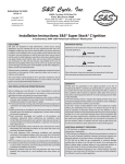
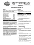
Saddlebag support
Lower saddlebag guard
Compass sensor
Lower saddlebag guard screw
Upper saddlebag guard screw
Support bracket
Support bracket screw and locknut
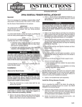
Figure 1. Compass Sensor Mounting
(Model with Saddlebag Guards Shown)
4. See Figure 1. Remove the outboard screw and locknut
(7) attaching the existing sensor (3) and saddlebag support (1) to the support bracket (6).
Removing the Existing Sensor
1WARNING
To prevent accidental vehicle start-up, which could
cause death or serious injury, disconnect negative (-)
battery cable before proceeding. (00048a)
1. Refer to the Owner’s Manual and follow the instructions
given to remove the seat and disconnect the negative
battery cable. Retain all seat mounting hardware.
2. Remove the right-side saddlebag. Refer to SADDLEBAG REMOVAL in the appropriate Service Manual.
3. Cut the wires on the old sensor, a few inches away from
the sensor.
CAUTION
Torx®
drivers when
Do not use magnetic tools such as
installing the compass sensor. If the compass bracket
becomes magnetized, it will affect calibration and accuracy.
5. Remove the screw (4) and flat washer holding the upper
part of the sensor bracket (and the lower saddlebag
guard [2], if so equipped) to the support bracket.
Installing the New Compass Sensor Unit
6. Models WITHOUT Saddlebag Guards: Attach the new
compass sensor (3) to the support bracket (6) through
the upper hole with the flat washer and screw (4)
removed in Step 5.
Models WITH Saddlebag Guards: Attach the new
compass sensor (3) to the lower saddlebag guard (2)
and the support bracket (6) through the upper hole with
the flat washer and screw (4) removed in Step 5.
7. All models: Attach the compass sensor to the support
bracket (6) and the saddlebag support (1) through the
lower hole with the nut and screw (7) removed in Step 4.
1 of 4
Routing the Compass Sensor Cable
Final Assembly
1. See Figure 1. Remove the screw (5) fastening the compass sensor cable clamp to the support bracket, and
pull the old cable from the clamp. Insert the cable from
the new compass sensor into the clamp, and re-fasten
the clamp to the support bracket.
In order to connect the new compass sensor to the compass
display in the motorcycle fairing, the old compass sensor
harness must be cut in the area under the seat. A sixposition Deutsch connector (included in the kit) will then be
assembled to the front portion of the existing harness, and
plugged into the new sensor harness.
2 Remove the old cable from the motorcycle as you lead
the new cable up the right side saddlebag support
bracket (6), and forward along the fender support bracket and frame strut. Secure the new cable with cable ties
from the kit at the same points as the old cable.
NOTE
When cutting the existing harness, make sure the wires from
the front of the bike are long enough to reach the service
harness connector without stretching, pinching or rubbing.
3. Route the cable through the opening in the frame gusset,
under the turn signal/security module (if so equipped) and
behind the battery to the left side of the motorcycle.
1. Cut the wires of the original compass sensor harness in
the area under the seat so that the wires coming from
the fairing will reach the service harness connector.
4. Run the cable along the left side of the battery. Unplug
the existing cable from the switched accessory connector, located in front of the battery. Plug the four-position
Deutsch connector from the new compass sensor into
the accessory connector.
2. Obtain the Deutsch socket, terminals and related parts
from the kit. See a 1998 or later FLT Service Manual for
Deutsch Solid Barrel Contact Crimping Instructions. Follow
instructions to terminate the wires from the old compass
sensor harness.
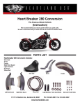
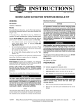
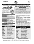
3. See Figure 2. Insert the terminals into the connector
half as shown.
i05110
1 2 3
4 5 6
4. Insert the seal pin in the unused cavity.
5. Connect the old compass harness to the new sensor
harness.
Open
Orange/White
6. Install the right-side saddlebag. Refer to SADDLEBAG
INSTALLATION in the appropriate Service Manual.
Green
Purple
7. Refer to the Owner’s Manual and follow the instructions to
re-attach the negative battery cable and install the seat.
White
Yellow
1WARNING
After installing seat, pull upward on front of seat to be
sure it is in locked position. While riding, a loose seat
can shift causing loss of control, which could result in
death or serious injury. (00070a)
Figure 2. Connection Diagram
1
16
16
(NNW)
(N)
1
2
15
3
15
(NW)
2
(NNE)
i04776c
14
4
14
(WNW)
13
3
5
13
(W)
(NE)
6
12
12
(WSW)
4
7
11
10
(ENE)
5 (E)
6 (ESE)
7
8
(SE)
(SSE)
9 (S)
10
11
(SSW) (SW)
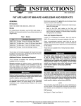
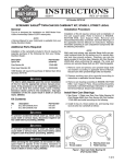
Figure 3a. Zone Chart for the "Lower 48" States
(With Compass Gauge Equivalents)
9
8
Figure 3b. Zone Equivalents on the
Compass Gauge
Figure 3
-J02461
2 of 4
Setting the Zone and Re-calibrating the Compass
CAUTION
Upon initial power up of the compass after installation of
the new sensor, the gauge will continually spin until zone
selection and calibration procedures have been successfully completed.
With the new sensor installed, the compass must be adjusted to operate in the zone in which it will be used. Therefore,
the correct zone must again be programmed into the compass. See Figure 3a for locations within the “lower 48”
United States. See Figure 4 for Canada and Alaska. Hawaii
is in zone seven. Travel across several zones should not significantly affect compass accuracy.
1
16
(NNW)
(N)
3
(NE)
i04899a.eps
See Figure 3b. The compass gauge display is used to indicate the zone currently selected or stored in memory. “N”
indicates zone one is selected, “NNE” indicates zone two,
and so on.
4
(ENE)
5 6
(E)
(ESE)
7
(SE)
(SSE)
Reposition the
motorcycle and
prepare to drive in
opposite direction.
about 3 sec.
Turn ignition
switch "ON".
within 10 sec.
Quickly cycle the
accessory rocker
switch 3 times
("ON"-"OFF""ON"-"OFF""ON"-"OFF"
within 2 seconds).
Gauge spins to
"N", indicating
zone stored and
"calibration" mode
entered.
Turn accessory
rocker switch "ON".
Position the
motorcycle on level
ground, in area free
of large buildings,
power lines, etc.,
and prepare to
drive in circles,
Gauge spins to
"N", indicating
"calibration" mode
is again entered.
immediately
Start driving
counterclockwise in
consistent circles
at constant speed
and constant
turning radius.
Continue driving
until gauge
displays the
current direction
(about 60 seconds).
Turn accessory
rocker switch "OFF".
"Zone selection"
mode entered.
Gauge stops
spinning,
immediately
Determine correct
zone per chart.
within 10 sec.
Cycle the
accessory rocker
switch 1 time
("ON"-"OFF")
to advance one
zone (if needed).
within 10 sec.
13 (W)
12(WSW)
11(SW)
10 (SSW)
NOTE: For Hawaii calibrate to Zone 7 (SE)
Turn accessory
rocker switch "ON".
Upon initial power
up, gauge will
continually spin
until calibration
is complete.
8
9(S)
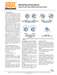
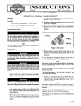
Figure 4. Zone Chart for Alaska and Canada
(With Compass Gauge Equivalents)
The compass must also be re-calibrated after sensor
replacement. This allows the new sensor to compensate for
the influence of the motorcycle structure in its determination
of the correct heading.
i02464a
15 (NW)
14 (WNW)
2
(NNE)
Start driving
clockwise in
consistent circles
at constant speed
and constant
turning radius.
Continue driving
until gauge
displays "S"
(about 60 seconds).
After the second calibration period:
• If the calibration was valid, the compass
will begin to operate normally and show
the current heading.
• If the calibration was not valid, the compass
will continually spin. If this happens, perform
the entire calibration procedure again.
• If the compass shows an incorrect heading,
but does not spin, use the re-calibration
procedure on the cut-off reference, page 6.
Continue cycling
the accessory
rocker switch
("ON"-"OFF")
until correct zone
is displayed.
Figure 5. Zone Selection and Re-calibration Procedure
-J02461
3 of 4
The zone-setting and re-calibration of the compass can be
accomplished by following the flow chart in Figure 5.
Please read through and understand the entire flow chart
before starting the re-calibration procedure.
• The re-calibration procedure involves driving the
motorcycle in large diameter circles (30-40 ft) (9-12 M)
on level ground free of large buildings, power lines, etc.
Calibration information is stored in non-volatile memory, and
re-calibration will not be needed if power to the unit is disconnected. However, when travel to another zone introduces noticeable inaccuracy the new zone should be stored
in memory in order to maintain compass accuracy.
• An on/off sequence of the accessory rocker switch
(located on the inner fairing dash panel) will set the
zone and initiate re-calibration.
• The quality of the calibration is directly dependent on
the consistency of the circles driven during calibration.
• Two sets of equal -size circles, driven in opposite
directions, are required.
®
Service Parts
Part No. 74633-02A
Date 03/04
Electronic Compass Sensor Service Kit
i05109
10
2, 3, 4, 5
1
13
11
12
6, 7, 8, 9
14
Item Description (Quantity)
1
Sensor, electronic compass (includes items 2 through 9)
2
Socket housing, 4-cavity
3
Secondary lock, 4-cavity
4
Terminal, socket (2)
5
Plug, seal pin (2)
6
Pin housing, 6-cavity
7
Secondary lock, 6-cavity
8
Terminal, pin (5)
9
Plug, seal pin
10
Cable strap, (6) 0.19 x 7.5 in (5 x 190 mm)
11
Socket housing, 6-cavity
12
Secondary lock, 6-cavity
13
Terminal, socket (5)
14
Plug, seal pin
-J02461
Part No.
Not sold separately
72114-94BK
72154-94
72191-94
72195-94
74106-98BK
74146-98
74190-98
74195-98
10006
74116-98BK
74156-98
74191-98
74195-98
4 of 4