1
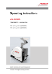
Operating instructions
PARTICLE SIZER
ANALYSETTE 28 IMAGESIZER
Valid starting with: 28.2000/00100
Read the instructions prior to performing any task!
Translation of the original operating instructions
Fritsch GmbH
Milling and Sizing
Industriestraße 8
D - 55743 Idar- Oberstein
Telephone: +49 (0)6784/ 70-0
Fax: +49 (0)6784/ 70-11
Email: [email protected]
Internet: www.fritsch-sizing.de
Version 01/2014 Index 003
Certifications and CE conformity
Certifications and CE conformity
Certification
Fritsch GmbH has been certified by the TÜV-Zertifizierungsgemeinschaft
e.V.
An audit certified that Fritsch GmbH conforms to the requirements of
the DIN EN ISO 9001:2008.
CE Conformity
The enclosed Conformity Declaration lists the guidelines the FRITSCH
instrument conforms to, to be able to bear the CE mark.
-3-
Table of contents
Table of contents
1
Basic structure............................................................................... 6
2
Safety information and use........................................................... 8
2.1 Requirements for the user..................................................... 8
2.2 Scope of application............................................................... 8
2.3 Obligations of the operator................................................... 9
2.4 Information on hazards and symbols used in this manual.... 9
2.5 Device safety information.................................................... 12
2.6 Hazardous points................................................................. 13
2.7 Electrical safety.................................................................... 14
2.7.1 General information......................................................... 14
3
Technical data..............................................................................
3.1 Dimensions..........................................................................
3.2 Weight..................................................................................
3.3 Operating noise....................................................................
3.4 Voltage.................................................................................
3.5 Current consumption...........................................................
3.6 Power consumption.............................................................
3.7 Electrical fuses.....................................................................
15
15
15
15
15
15
15
15
4
Installation...................................................................................
4.1 Transport and storage..........................................................
4.2 Unpacking............................................................................
4.3 Scope of delivery..................................................................
4.3.1 Accessory case..................................................................
4.3.2 Accessory tray...................................................................
4.4 Setting up.............................................................................
4.5 Ambient conditions..............................................................
4.6 Transport securing devices..................................................
4.7 Electrical connection............................................................
4.7.1 Stability of the mains voltage............................................
4.8 Preparation of the ANALYSETTE 28 ImageSizer...................
4.8.1 Connection of the camera to the lens and insertion........
4.9 Mounting the funnel............................................................
4.10 Preparation of the computer.............................................
4.11 Checking the communication between the device and
the PC.................................................................................
4.11.1 Checking the communication between the camera and
the PC..............................................................................
16
16
16
17
18
18
19
19
19
20
20
21
21
22
23
Using the device...........................................................................
5.1 Changing the lens.................................................................
5.1.1 Adjusting the camera angle..............................................
5.1.2 Changing the sample guide plate......................................
30
30
32
32
5
-4-
28
28
Table of contents
5.2 Fritsch test powder F16.......................................................
5.2.1 Filling with material and adjustment of the funnel
height................................................................................
5.2.2 Positioning the feeder.......................................................
5.2.3 Measuring with the ImageSizer........................................
33
34
35
6
Accessories...................................................................................
6.1 Lenses..................................................................................
6.2 Computer.............................................................................
6.3 Dust extraction system........................................................
36
36
36
37
7
Cleaning........................................................................................
7.1 Cleaning the device..............................................................
7.1.1 Cleaning the falling chute.................................................
7.2 Cleaning the lens..................................................................
7.3 Cleaning the windows..........................................................
7.3.1 Removal of the window holder.........................................
7.4 Cleaning the lens of the digital camera................................
38
38
38
38
39
39
40
8
Maintenance................................................................................ 41
9
Repairs......................................................................................... 42
9.1 Checklist for troubleshooting............................................... 42
10
Disposal........................................................................................ 44
11
Guarantee terms.......................................................................... 45
12
Exclusion of liability..................................................................... 47
13
Safety logbook............................................................................. 49
14
Index............................................................................................. 52
-5-
33
Basic structure
1
Basic structure
The designations below are used with the corresponding numbers in the
following operating instructions.
1
2
3
4
Funnel
Feed channel
Height-adjustable funnel holder
Funnel support column
5
6
7
8
-6-
Sample collection container
Latches
Housing flap
Base plate
Basic structure
9
10
11
12
13
5 MP digital camera
Lens holder
Lens
Lens holder end stop
Holder with optical glass window
18
19
20
21
Main switch
Ethernet connection
Mains connection
USB socket
14
15
16
17
22
-7-
Holder with frosted Plexiglas window
Flash unit
Falling chute
Sample guide plate
Setting ring
Safety information and use
2
Safety information and use
2.1 Requirements for the user
This operating manual is intended for persons assigned with operating
and monitoring the Fritsch ANALYSETTE 28 ImageSizer. The operating
manual and especially its safety instructions are to be observed by all
persons working on or with this device. In addition, the applicable rules
and regulations for accident prevention at the installation site are to be
observed. Always keep the operating manual at the installation site of
the ANALYSETTE 28 ImageSizer.
People with health problems or under the influence of medication,
drugs, alcohol or exhaustion must not operate this device.
The ANALYSETTE 28 ImageSizer may only be operated by authorised persons and serviced or repaired by trained specialists. All commissioning,
maintenance and repair work may only be carried out by technically
qualified personnel. Qualified personnel are persons who, because of
their education, experience and training as well as their knowledge of
relevant standards, regulations, accident prevention guidelines and operating conditions, are authorised by those responsible for the safety of
the machine to carry out the required work and are able to recognize
and avoid possible hazards as defined for skilled workers in IEC 364.
In order to prevent hazards to users, follow the instructions in this
manual.
Malfunctions that impair the safety of persons, the ANALYSETTE 28
ImageSizer or other material property must be rectified immediately.
The following information serves both the personal safety of operating
personnel as well as the safety of the products described and any
devices connected to them: All maintenance and repair work may only
be performed by technically qualified personnel.
This operating manual is not a complete technical description. Only the
details required for operation and maintaining usability are described.
Fritsch has prepared and reviewed this operating manual with the
greatest care. However, no guarantee is made for its completeness or
accuracy.
Subject to technical modifications.
2.2 Scope of application
The ANALYSETTE 28 ImageSizer is used for the analysis of the particle
shape and size of powders and bulk solids. The particle sizer has an
extra-large measuring range of 20 µm to 20 mm! It is therefore an ideal
device for uncomplicated quality control in various areas of application.
The particle sizer described here is an operations resource for use in
industrial environments. This operations resource possesses hazardous
live components during operation.
-8-
Safety information and use
2.3 Obligations of the operator
Before using the ANALYSETTE 28 ImageSizer, this manual is to be carefully read and understood. The use of the ANALYSETTE 28 ImageSizer
requires technical knowledge; only commercial use is permitted.
The operating personnel must be familiar with the content of the operating manual. For this reason, it is very important that these persons
actually receive the present operating manual. Ensure that the operating
manual is always near the device.
The ANALYSETTE 28 ImageSizer may exclusively be used within the scope
of applications set down in this manual and within the framework of
guidelines put forth in this manual. In case of non-compliance or
improper use, the customer assumes full liability for the functional capability of the ANALYSETTE 28 ImageSizer and for any damage or injury
arising from failure to fulfil this obligation.
By using the ANALYSETTE 28 ImageSizer the customer agrees with this
and recognizes that defects, malfunctions or errors cannot be completely
excluded. To prevent risk of damage to persons or property or of other
direct or indirect damage, resulting from this or other causes, the customer must implement sufficient and comprehensive safety measures
for working with the ANALYSETTE 28 ImageSizer.
Neither compliance with this manual nor the conditions and methods
used during installation, operation, use and maintenance of the ANALYSETTE 28 ImageSizer can be monitored by Fritsch GmbH. Improper execution of the installation can result in property damage and thus
endanger persons. Therefore, we assume absolutely no responsibility or
liability for loss, damage or costs that result from errors at installation,
improper operation or improper use or improper maintenance or are in
any way connected to these.
The applicable accident prevention guidelines must be complied with.
Generally applicable legal and other obligatory regulations regarding
environmental protection must be observed.
2.4 Information on hazards and symbols used in this manual
Safety information
Safety information in this manual is designated by symbols. Safety information is introduced by keywords that express the extent of the hazard.
DANGER!
This symbol and keyword combination points out a directly
hazardous situation that can result in death or serious
injury if not avoided.
-9-
Safety information and use
WARNING!
This symbol and keyword combination points out a possibly
hazardous situation that can result in death or serious
injury if not avoided.
CAUTION!
This symbol and keyword combination points out a possibly
hazardous situation that can result in slight or minor injury
if not avoided.
NOTICE!
This symbol and keyword combination points out a possibly
hazardous situation that can result in property damage if
not avoided.
ENVIRONMENT!
This symbol and keyword combination points out a possibly
hazardous situation that can result in environmental
damage if not avoided.
Special safety information
To call attention to specific hazards, the following symbols are used in
the safety information:
DANGER!
This symbol and keyword combination points out a directly
hazardous situation due to electrical current. Ignoring information with this designation will result in serious or fatal
injury.
DANGER!
This symbol and keyword combination designates contents
and instructions for proper use of the machine in explosive
areas or with explosive substances. Ignoring information
with this designation will result in serious or fatal injury.
- 10 -
Safety information and use
DANGER!
This symbol and keyword combination designates contents
and instructions for proper use of the machine with combustible substances. Ignoring information with this designation will result in serious or fatal injury.
WARNING!
This symbol and keyword combination points out a directly
hazardous situation due to movable parts. Ignoring information with this designation can result in hand injuries.
WARNING!
This symbol and keyword combination points out a directly
hazardous situation due to hot surfaces. Ignoring information with this designation can result in serious burn injuries
due to skin contact with hot surfaces.
Safety information in the procedure
instructions
Safety information can refer to specific, individual procedure instructions. Such safety information is embedded in the procedure instructions
so that the text can be read without interruption as the procedure is
being carried out. The keywords described above are used.
Example:
1.
Loosen screw.
2.
CAUTION!
Risk of entrapment at the lid.
Close the lid carefully.
3.
Tighten screw.
Tips and recommendations
This symbol emphasises useful tips and recommendations
as wells as information for efficient operation without mal‐
function.
Further designations
To emphasise procedure instructions, results, lists, references and other
elements, the following designations are used in this manual:
- 11 -
Safety information and use
Designation
Explanation
Step-by-step procedure instructions
1., 2., 3. ...
ð
Results of steps in the procedure
References to sections in this manual and relevant documentation
Lists without a specific order
[Button]
Operating elements (e.g. push button, switch),
display elements (e.g. signal lamps)
‘Display’
Screen elements (e.g. buttons, function key
assignment)
2.5 Device safety information
n The particle sizer has been designed from the viewpoint of safety to
users; nevertheless, residual hazards cannot be ruled out.
n The device may only be used for the purpose described under
Ä ‘Scope of application’ on page 8.
n Only use original accessories and original spare parts. Failure to
observe this instruction can compromise the safety of the machine.
n Safe conduct must be strictly observed during all work with the
device.
n All currently applicable national and international accident prevention guidelines must be complied with.
n Do not remove the information signs.
DANGER!
Explosion hazard!
– The device is not explosion-protected!
– The device must not be used in electrically conductive,
dusty or damp environments.
DANGER!
Mains voltage
– Do not allow any liquids to run inside the device.
- 12 -
Safety information and use
WARNING!
The maximum accepted concentration (MAC) levels of the
valid safety regulations must be observed. If necessary,
ventilation must be provided or the machine must be operated under an extractor hood.
NOTICE!
Immediately replace damaged or illegible information signs.
n Unauthorised alterations will void Fritsch's declaration of conformity
to European directives and void the guarantee.
n If after reading the operating manual you still have questions or
problems, please do not hesitate to contact our technical specialists.
2.6 Hazardous points
DANGER!
There is a risk of fatal injuries from power surges when
cleaning the device. Disconnect the mains plug before
cleaning the device.
CAUTION!
Crushing hazard!
When
–
–
–
–
–
–
Moving the funnel
Closing the device
Inserting the holders with the "measuring windows" 13
+ 14
Inserting the lenses
Mounting the camera
Inserting the sample collection container
NOTICE!
Do not leave any oxidizing parts on the channel or in the
funnel - risk of corrosion.
- 13 -
Safety information and use
2.7 Electrical safety
2.7.1
General information
n The main switch separates the device from the power supply on two
poles.
n Switch off the main switch if the ANALYSETTE 28 ImageSizer is to
stand idle for a longer duration (e.g. overnight).
In the switched-on state, the switch is illuminated red and the control
lamp on the front side blue.
- 14 -
Technical data
3
Technical data
3.1 Dimensions
84 x 20 x 28 cm (width x depth x height without funnel and feed channel)
3.2 Weight
43,8 kg net
3.3 Operating noise
The noise level is up to approx. 78 dB(A).
3.4 Voltage
The voltage range is from 100 - 240 V.
3.5 Current consumption
The maximum current consumption is 0.2 A (230 V), 0.6 A (115 V) .
3.6 Power consumption
The maximum power consumption is 50 W.
3.7 Electrical fuses
Micro-fuse 5 x 20 mm 2A slow-blow, 2 pieces The fuses are located
inside the mains power socket (19).
- 15 -
Installation
4
Installation
4.1 Transport and storage
DANGER!
Do not step under the transport pallet during transport.
The ANALYSETTE 28 is delivered in a wooden crate on a pallet. Do not tilt
or stack this crate. The ImageSizer must be transported and stored in its
packaging and protected from weather and outside influences.
Transport over larger distances only in the original Fritsch packaging.
We recommend using a forklift or pallet truck for transporting the
packed device.
WARNING!
Improper lifting can lead to personal injury or property
damage. The machine is only to be lifted with suitable
equipment and by qualified personnel.
The guarantee excludes all claims for damage due to improper transport.
4.2 Unpacking
Remove the transport packaging as shown in the following illustrations.
- 16 -
Installation
1.
Cut open the straps of the package using side cutters.
2.
Remove the staples using an appropriate tool.
3.
Lift the lid off.
The accessory case and the funnel (1) can now be seen.
4.
Remove the surrounding packaging.
5.
Take out the accessory case and the funnel.
6.
Remove the foam mouldings and lift the ImageSizer from the
transport cradle using two persons.
NOTICE!
Do not use the channel to lift the ANALYSETTE 28
from the transport cradle.
For lifting, reach under the base plate (8).
If you have ordered the ANALYSETTE 28 ImageSizer with two
lenses, you will find the second lens stored vertically next to the
ImageSizer in a lens case (a).
4.3 Scope of delivery
Please check the delivery against your order! If the delivery is incomplete
or damaged, inform the shipping agent immediately and inform Fritsch
GmbH within 24 hours. Any claims received later cannot be considered.
- 17 -
Installation
4.3.1
Accessory case
2
4
5
6
7
8
9
Standard lens 150 - 20000 µm
Connection cable
Ethernet cable
Spoon spatula
Optics tissue
USB cable
USB stick with software, USB driver, operation
manual and software manual
10 5 MP digital camera
4.3.2
11
12
13
14
15
16
17
Antistatic cloth
Silicate
Flat brush
Lens brush
Soft Pad
Assembly gauge block
Hex key set
Inventory list
Accessory tray
n Funnel (1) with funnel holder (3) and end cap
- 18 -
Installation
4.4 Setting up
n Place the ANALYSETTE 28 ImageSizer on an even and stable surface
in an interior room.
NOTICE!
Never operate ANALYSETTE 28 ImageSizer while it is
standing on the transport pallet!
n Make sure that:
– all switches / control elements are easy to access;
– the USB and Ethernet interfaces are easy to access.
n Please store the transport packaging in order that it can be reused if
you need to return the product. Fritsch GmbH accepts no liability for
damage caused by improper packaging (non-original packaging).
4.5 Ambient conditions
WARNING!
Mains voltage
– The device may only be operated indoors.
– The surrounding air must not contain any electrically
conductive particles.
– Maximum relative humidity 80% for temperatures up
to 31 °C, linearly decreasing down to 50% relative
humidity at 40 °C.
n The room temperature should be between 5 and 40 °C.
n Storage and transport is possible between 1 and 40 °C.
n If stored or transported below 10 °C, you must wait until the device
has warmed up to ambient temperature before switching on.
4.6 Transport securing devices
The sample guide plate inside the device (17) is secured with adhesive
tape!
- 19 -
Installation
4.7 Electrical connection
DANGER!
Provide short-circuit protection!
Risk of damage due to short-circuits.
–
Make sure that the socket is connected to a mains line
protected with a residual current circuit breaker.
DANGER!
Mains voltage!
Changes to the connection line may only be made by a
qualified person.
Before establishing the connection, compare the voltage and current
values stated on the type plate with the values of the power supply
system to be used.
CAUTION!
Ignoring the values on the type plate may result in damage
to the electrical and mechanical components.
CAUTION!
Ensure that the mains supply provides a functional device
ground connection!
4.7.1
Stability of the mains voltage
Instruments with electronic components require a stable supply voltage
(+/- 10% deviation). For weak or non-interference free mains supplies
(voltage peaks through inductive load changes or switched-mode power
supplies), we recommend connecting via a voltage stabiliser and filter
(Art. No. 20.6000.00).
- 20 -
Installation
4.8 Preparation of the ANALYSETTE 28 ImageSizer
Open the front flap (7) forwards by lifting up both latches (6).
4.8.1
Connection of the camera to the lens and insertion
1.
Remove the caps from the camera and from the screw thread of
the lens. Screw the lens hand-tight onto the camera!
2.
Connect the camera as shown in the picture.
(a) Ethernet connection
(b) Power supply connector
(c) Process interface connector
- 21 -
Installation
3.
Insert the camera with lens. To do this, hold the lens tilted backwards in the device housing, as shown in the picture, and hook the
flat rail runner onto the rail from behind. Then tilt the lens forwards and position it on the rail. The lens holder can be moved
back and forth on the rail.
NOTICE!
Only remove the front cap from the lens once it is
located on the rail!
4.
Remove the front cap and push the flat rail runner in the direction
of the falling chute as far as the end stop.
5.
When the flat rail runner is at the end stop, lock it with the knurled
screw (b).
The lens is recognised automatically by the device and
shown in the software.
4.9 Mounting the funnel
You will find the funnel (24.0210.10) as described in Ä ‘Accessory case’
on page 18.
- 22 -
Installation
4.10
1.
Loosen the knurled screw of the funnel holder in a counter-clockwise direction.
2.
Push the funnel holder (3) over the funnel support column (4) and
lock with the knurled screw.
3.
Take the black cap (c) from the accessory compartment and push
it onto the column end.
Preparation of the computer
Computers provided by Fritsch GmbH are already equipped
with the software you need and can be used directly after
the device has been connected.
System requirements:
– Intel Core i7 Quad Core processor or equivalent
– Minimum of 8 GB system memory
– Primary drive: minimum of 256 GB SSD
– Secondary drive: 1 TB HDD
– NVIDIA graphics card
– Additional gigabit network interface card for the GigE
camera with support for JumboFrames (e.g. Intel Pro
1000)
– USB port
– 22" monitor with 1920 x 1080 pixels resolution or better
Software:
– Windows 7 or higher
– Adobe PDF reader
1.
Insert the supplied USB stick into the USB port on your PC provided for this purpose.
2.
Select the USB stick and run the CD_Start application on this.
3.
Select the ANALYSETTE 28.
- 23 -
Installation
4.
Select ImageSizer.
5.
Install the 64-bit version of the USB driver. (If you have already
installed the newest FTDI-USB driver on your system, you do not
need to install this in addition.)
6.
Then install the camera driver.
7.
Following this, connect the ImageSizer to the PC using the supplied
USB cable (26)!
NOTICE!
When connecting the USB cable, make sure that the
USB plug is in the correct position. Connecting the
cable incorrectly to the ANALYSETTE 28 can result in
property damage or a connection problem with the
PC.
8.
Make an Ethernet connection between the ImageSizer and the
additional PC network interface card using the supplied Ethernet
cable!
Ensure that the second network interface card is con‐
figured with a fixed IP (192.x.x.x or 169.x.x.x). For any
questions about configuring your network interface
card, please contact your system administrator.
The pictures produced by the camera are sent to the
PC via the Ethernet connection.
- 24 -
Installation
9.
Install the Image Sizing Software (ISS).
10.
Select a language for the installation.
11.
A welcome window for the "Image Sizing Software" Set-up Wizard
opens. Click on "Next" to continue the installation.
12.
The default target folder for the installation is C:\Program Files.
Click on "Next" to continue the installation.
- 25 -
Installation
13.
You can now start the installation by clicking on the "Install"
button.
14.
Finish the installation by clicking on "Close".
15.
A FRITSCH ANALYSETTE 28 icon "ISS.exe" has now been placed on
the desktop.
- 26 -
Installation
16.
To start the program without the desktop icon, proceed as follows:
n Start Windows Explorer.
n The target folder shown during the installation contains the
folder "Fritsch GmbH".
n In this folder, open the folder "Image Sizing Software".
n This "Image Sizing Software" folder contains the file "ISS.exe",
with which the program can be started manually! Double-click
on the file "ISS.exe" to start the program.
After initially starting the software you must specify the
memory location for the measuring data.
- 27 -
Installation
4.11
Checking the communication between the device and the PC
You have the possibility in the Image Sizing software to check whether
the device has been recognised by the PC and which COM port it is
installed on. Proceed as follows:
1.
Click on the icon "ISS.exe" to start the Image Sizing software.
2.
Click on ‘Configuration’ to go to the configuration settings.
3.
In the left part of the screen, the software opens a new window
with the various configuration options. Click on ‘Select device’ .
4.
In this window, the interface used and the attached device with
specifications are shown automatically. If no device is displayed,
click on ‘Search’ . This should list all detected devices which are
connected to the system. Clicking on a device selects it as the current device and the software is restarted.
If no device is found, check whether the device is
switched on. If so, check the used drivers and right
connections of the used ports on your PC and device.
4.11.1
Checking the communication between the camera and the PC
1.
Click on the icon "ISS.exe" to start the Image Sizing software.
2.
Click on ‘Configuration’ to go to the configuration settings.
- 28 -
Installation
3.
In the left part of the screen, the software opens a new window
with the various configuration options. Click on ‘Measurement
settings’ .
4.
Then, click on ‘setup’ next to "Detect optimal camera settings".
5.
When the camera has been recognized, you can test the image
transfer and the camera function by holding a brush or pencil in
the falling chute, whereby the object will be displayed in the
"Camera Set-up" window.
6.
If this is the case, then the communication between the camera
and the PC is functioning correctly.
If no image is received from the camera, this can have
various causes. Check the IPs and subnet masks
entered under "Interface" and "Camera". The two IPs
must correspond to the subnet masks. (In the
example shown: 192.160.100.x) The IP entered under
Interface must correspond to the IP of the network
interface card that the camera is connected to.
To avoid problems with the initial start‐up, connect
the ANALYSETTE 28 to the PC and install the software
before connecting the system to a LAN.
- 29 -
Using the device
5
Using the device
Soiling of the glasses/windows can lead to incorrect meas‐
urement results. It is therefore essential that these be
cleaned. The windows should be checked for soiling after
every measurement.
Depending on the type of sample, the lens, the windows
and the digital camera lens must be checked for soiling
before each measurement or measurement series and
cleaned if necessary. Also, if smearing or permanent dots
can be seen in the picture transmitted by the camera during
camera adjustment or when making a measurement, the
components mentioned must be checked and cleaned, as
described in Ä ‘Cleaning’ on page 38!
The Soft Pad (34) provided is intended to protect the top
surface of the housing should anything be placed upon it.
5.1 Changing the lens
The camera can be left connected to the cables while
changing the lens.
The lens is recognised automatically by the device and
shown in the software.
- 30 -
Using the device
1.
Open the front flap forwards by lifting up both latches (6).
2.
Loosen the knurled screw on the flat rail runner and pull the
runner backwards away from the falling chute.
3.
Place the cap on the lens.
4.
Tilt the lens backwards and remove the flat rail runner upwards.
5.
Unscrew the lens from the camera, attach the rear lens cap and
store in the accessory case.
- 31 -
Using the device
6.
5.1.1
Now, as described in Ä ‘Connection of the camera to the lens and
insertion’ on page 21, connect the other lens to the camera and
place it in the device.
Adjusting the camera angle
The lenses are preassembled with the holders in such a way that all that
is left to do is screw them to the digital camera. If, nevertheless, a lens is
twisted out of position, it is possible to correct this:
1.
Attach the camera to the lens.
2.
Remove the 2 hexagon screws closest to you.
3.
Turn the lens until the camera is once again correctly aligned with
the lens.
4.
Once this position has been found, fix the lens in place again with
the two hexagon screws.
Make sure that the setting ring lies flush against the
right holder.
5.
5.1.2
Now the lens is positioned correctly in the lens holder.
Changing the sample guide plate
To ensure exact positioning of the material to be measured in the focal
range of the lens, the device is provided with the corresponding sample
guide plates.
The gap width of the sample guide plate must be at least
three times the diameter of the material to be measured.
Change the guide plates as follows:
- 32 -
Using the device
1.
Open the front flap (7) forwards by lifting up both latches (6).
2.
Remove the sample guide plate (17) from its slot as shown in the
picture.
3.
Slide the guide plate that corresponds to the lens into the device.
5.2 Fritsch test powder F16
5.2.1
Filling with material and adjustment of the funnel height
1.
Loosen the knurled screw on the funnel holder and push the
holder downwards until the funnel exit is sitting on the feeder (2).
2.
Place the sample material in the funnel.
3.
Depending on the size of the material to be measured, move the
funnel slightly upwards and lock it again with the knurled screw.
Depending on the flowing properties and size of the mate‐
rial, a smaller gap (for fine powder with good flowing prop‐
erties) or a larger gap (for coarse material) between the
funnel and the feeder is needed. The gap to the feeder
should be about three times the maximum diameter of the
material.
- 33 -
Using the device
5.2.2
Positioning the feeder
The adjustable feeder positioning gives you another way of
feeding the sample material to the system optimally in the
focal range.
You can change the position of the feeder as follows:
1.
Remove the sample guide plate and insert the assembly gauge
block in the opening of the falling chute.
2.
Loosen the four hexagon socket-screws on the feeder.
3.
Depending on the starting position, move the channel towards the
falling chute or towards the funnel support column (4).
4.
Pay attention to the assembly gauge block while securing the
feeder in place. This should lie parallel to the feeder.
5.
Re-tighten the four hexagon socket screws.
After positioning the feeder and while initially feeding
in the sample, note how the sample is fed to the
falling chute. If the sample flows on one side of the
channel, tighten the hexagon socket screws a little
until the sample falls properly across the entire width
of the feeder into the falling chute.
The feeder must be positioned according to the par‐
ticle size and property of the sample. The optimum
position of the feeder should be determined through
experimentation.
- 34 -
Using the device
5.2.3
Measuring with the ImageSizer
You can check the precision and accuracy of your device by
measuring the Fritsch test powder at least once a week,
depending on how often you use the device. This will indi‐
cate contamination or malfunctions in your system.
Measure the supplied Fritsch test powder F16 with the ANALYSETTE 28
ImageSizer as follows:
1.
Set the device to I (On) with the main switch.
2.
Start the Image Sizing software.
3.
Create a new folder in the archive.
4.
A "New Project Case" must be created In the newly created folder.
5.
In this project case you can select the SOP "F16 Standard
measure" by clicking on "New measurement".
SOP refers to a Standard Operating Procedure used in
our software. In an SOP, work steps are pre‐defined
and processed with a single keystroke.
Ensure that you select the SOP which is suitable for
your device.
6.
The measuring window with the live image, camera and flash settings opens.
7.
The particle density thresholds are also displayed and, if necessary
and depending on the setting in the SOP, you can still vary the
feeder intensity. If the threshold is in the green area, you can start
the measurement.
8.
Once the cancellation criteria "Image count" or "Particle count"
are reached, the measurement is finished and you can display the
evaluation by clicking on "Stop" and "Close.
9.
When the measurement is finished, remove the sample from the
collecting vessel and clean the parts that come into contact with
the samples before you begin to measure other materials.
- 35 -
Accessories
6
Accessories
Operating instructions for the optional accessories, such as computer,
dust extraction system, colour inkjet printer or laser printer, can be
found in the packaging of the respective device.
6.1 Lenses
1.
The standard lens provided is the bi-telecentric lens for particle
sizes of 150 - 20000 µm. (28.2011.00)
2.
Bi-telecentric lens for a measuring range of 58 - 7400 µm.
(28.2012.00)
3.
Bi-telecentric lens for a measuring range of 20 - 2700 µm.
(28.2014.00)
4.
Bi-telecentric lens for a measuring range of 28 - 3500 µm.
(28.2013.00)
6.2 Computer
Computer incl. monitor for ANALYSETTE 28 with keyboard and Windows.
(Art. No.: 83.5641.00)
- 36 -
Accessories
6.3 Dust extraction system
Dust extraction system for dust categories "M" (Art. No.: 43.9050.00)
and "H" (Art. No.: 43.9010.00).
- 37 -
Cleaning
7
Cleaning
Depending on the type of sample, the lens, the windows
and the digital camera lens must be checked for soiling
before each measurement or measurement series and
cleaned if necessary. Also, if smearing or permanent dots
can be seen in the picture transmitted by the camera during
camera adjustment or when making a measurement, the
components mentioned must be checked and cleaned, as
described in Ä ‘Cleaning’ on page 38!
7.1 Cleaning the device
DANGER!
Mains voltage!
– Before beginning with cleaning work, disconnect the
mains plug and protect the device against being unintentionally switched back on!
– Do not allow any liquids to flow into the device.
– Indicate cleaning work with warning signs.
– Put safety equipment back into operation after
cleaning work.
When switched off, the device can be cleaned using a moist cloth or a
microfibre cloth.
7.1.1
Cleaning the falling chute
First remove the sample guide plate (17). Remove residual material from
the falling chute (16) using the brush (32)!
7.2 Cleaning the lens
Clean the front and rear lens elements using the lens brush (33). In case
of heavy soiling, use the antistatic cloth (30) to remove dirt from the
lenses.
For cleaning the lens, a separate description from the man‐
ufacturer is provided in the accessory case. These instruc‐
tions must be closely observed!
- 38 -
Cleaning
7.3 Cleaning the windows
The optical glass window (13) and the Plexiglas window (14) require no
special cleaning measures. It is sufficient to rinse them with water and
allow them to dry, or to clean them with the optics tissue (25) provided
in the accessory case.
During insertion, ensure that the optical glass window (13)
is inserted between the falling chute (16) and the lens (11),
and the frosted Plexiglas window (14) between the falling
chute (16) and the flash unit (15).
7.3.1
Removal of the window holder
The holders for the two windows are attached to the falling chute by
four magnets each.
Holder with optical glass window
1.
To remove the holders, simply tilt the handle of the holder forwards.
2.
In this way, the magnets are released and the holders can be
pulled out.
3.
On reinsertion, the magnetic attraction ensures correct positioning.
- 39 -
Cleaning
Holder with frosted Plexiglas window
1.
The Plexiglas window is removed in the same way as the optical
glass window.
2.
Also proceed in the reverse manner when reinserting.
7.4 Cleaning the lens of the digital camera
If smearing or fixed dots can be seen on the picture transmitted by the
camera, all components must be checked! If the windows and the lens
have been cleaned, but the soiling is still visible, check the camera by
turning it. If the soiling moves in the turning direction of the camera, the
soiling must be on the glass cover of the sensor.
CAUTION!
On no account may the camera lens be put under mechanical stress during cleaning.
The lens must be cleaned using the lens brush (33) and the optics tissue
(25) located in the accessory case.
- 40 -
Maintenance
8
Maintenance
DANGER!
Mains voltage
– Before beginning with maintenance work, unplug the
mains plug and protect the device against being unintentionally switched back on again!
– Indicate maintenance work with warning signs.
– Maintenance work may only be performed by specialised personnel.
– Put safety equipment back into operation after maintenance or repair work.
The ANALYSETTE 28 ImageSizer is - with the exception of regular cleaning
- maintenance-free.
We recommend keeping a safety logbook Ä Chapter 13
‘Safety logbook’ on page 49, where all work (maintenance,
repairs......) performed on the device is entered.
- 41 -
Repairs
9
Repairs
DANGER!
Mains voltage!
– Before beginning with repair work, unplug the mains
plug and protect the device against being unintentionally switched back on.
– Indicate repair work with warning signs.
– Repair work may only be performed by specialised personnel.
– Put safety equipment back into operation after maintenance work.
9.1 Checklist for troubleshooting
Fault description
Cause
Remedy
"ANALYSETTE 28 device not found";
"Camera not found"
USB cable not connected Remove the USB cable and make sure that the
correctly!
USB plug is in the correct position when reconnecting it. Start the software again!
Ethernet cable not connected correctly!
Check Ethernet cable and connect it properly to
the device and PC! Start the software again!
Main switch at 0 (OFF)
Switch on main switch.
No mains connection
Plug in mains plug and switch on the device!
Particle density during measurement Too much sample mateis too high
rial is being fed
Reduce the feed rate (see "ISS" software manual)
Gap between funnel and
feeder too large
Lower the funnel! Reduce the gap between the
funnel and feeder. (see Ä ‘Filling with material
and adjustment of the funnel height’ on page 33)
Lens for wrong measuring range used
Insert lens for the required measuring range
Material is not distributed in the focal range
Insert smaller sample guiding plate or align the
feeder optimally
Blurred images
Lens installed incorrectly Push lens forward as far as the end stop of the
lens holder and screw it tight. (see Ä point 5 on
page 21)
While setting the camera in the
"Measurement settings" configuration item, a black image is shown.
Device was not recognised
- 42 -
Search for the device in the "device selection"
configuration item and select it! (see point 1
"ANALYSETTE 28 device not found"; "Camera not
found")
Repairs
Fault description
Cause
Remedy
USB cable not connected Check USB cable and connect it properly to the
correctly
device and PC! Start the software again!
Protective lens cap not
removed
Remove protective lens cap (see Ä point 4 on
page 21)
Camera not connected
correctly
Check the camera connections! Start the software
again! (see Ä point 2 on page 21)
No commands executed by the A28!
USB cable not connected Check USB cable and connect it properly to the
correctly
device and PC! Start the software again!
No settings can be made in the
feeder 'setup'
USB cable not connected Check USB cable and connect it properly to the
correctly
device and PC! Start the software again!
Dots are visible in the same places in Soiled windows, lens or
all images
camera lens
Clean these parts as described in Ä ‘Cleaning’
on page 38!
Dark corners are visible in the preview image while setting up the
camera
Optimise camera settings (gain, gamma, flash)
Camera settings not correctly adjusted
- 43 -
Disposal
10
Disposal
It is hereby confirmed that FRITSCH has implemented the directive
2002/95/EC of the European Parliament and Council from 27th January
2003 for the limitation of the use of certain dangerous substances in
electrical and electronic devices.
FRITSCH has registered the following categories according to the German
electrical and electronic equipment act, section 6, paragraph 1, clause 1
and section 17, paragraphs 1 and 2:
Mills and devices for the preparation of samples have been registered
under category 6 for electrical and electronic tools (except for large stationary industrial tools).
Analytical devices have been registered under category 9, monitoring
and control instruments.
It has been accepted that FRITSCH is operating only in the business-tobusiness area. The German registration number for FRITSCH is WEEE reg.
no. DE 60198769
FRITSCH WEEE coverage
Since the registration of FRITSCH is classified for bilateral transactions,
no legal recycling or disposal process is described. FRITSCH is not obliged
to take back used FRITSCH devices.
FRITSCH declares it is prepared to take back used FRITSCH devices for
recycling or disposal free of charge whenever a new device is purchased.
The used FRITSCH device must be delivered free of charge to a FRITSCH
establishment.
In all other cases FRITSCH takes back used FRITSCH devices for recycling
or disposal only against payment.
- 44 -
Guarantee terms
11
Guarantee terms
Guarantee period
As manufacturer, FRITSCH GmbH provides – above and beyond any guarantee claims against the seller – a guaranty valid for the duration of two
years from the date of issue of the guarantee certificate supplied with
the device.
Within this guarantee period, we shall remedy all deficiencies due to
material or manufacturing defects free of charge. Rectification may take
the form of either repair or replacement of the device, at our sole discretion. The guarantee may be redeemed in all countries in which this
FRITSCH device is sold with our authorisation.
Conditions for claims against the guarantee
This guarantee is subject to the condition that the device is operated
according to the instructions for use / operating manual and its intended
use.
Claims against the guarantee must include presentation of the original
receipt, stating the date of purchase and name of the dealer, together
with the complete device type and serial number.
For this guarantee to take effect, the answer card entitled "Securing of
Guarantee" (enclosed with the device) must be properly filled out and
despatched without delay after receipt of the device and be received
by us within three weeks or alternatively, online registration must be
carried out with the above-mentioned information.
Reasons for loss of the guarantee
The guarantee will not be granted in cases where:
n Damage has arisen due to normal wear and tear, especially for wear
parts, such as: Crushing jaws, support walls, grinding bowls, grinding
balls, sieve plates, brush strips, grinding sets, grinding disks, rotors,
sieve rings, pin inserts, conversion kits, sieve inserts, bottom sieves,
grinding inserts, cutting tools, sieve cassettes, sieve and measuring
cell glasses.
n Repairs, adaptations or modifications were made to the device by
unauthorized persons or companies.
n The device was not used in a laboratory environment and/or has
been used in continuous operation.
n Damage is present due to external factors (lightning, water, fire or
similar) or improper handling.
n Damage is present that only insubstantially affects the value or
proper functioning of the device.
n The device type or serial number on the device has been changed,
deleted, removed or in any other way rendered illegible
n The above-mentioned documents have been changed in any way or
rendered illegible.
- 45 -
Guarantee terms
Costs not covered by the guarantee
This guarantee excludes any costs for transport, packaging or travel that
accrue in the event the product must be sent to us or in the event that
one of our specialist technicians is required to come to your site. Any
servicing done by persons not authorised by us and any use of parts that
are not original FRITSCH accessories and spare parts will void the guarantee.
Further information about the guarantee
The guarantee period will neither extend nor will a new period of guarantee begin in the event that a claim is placed against the guarantee.
Please provide a detailed description of the type of error or the complaint. If no error description is enclosed, we shall interpret the shipment
as an assignment to remedy all recognisable errors or faults, including
those not covered by the guarantee. Errors or faults not covered by the
guarantee shall in this case be rectified at cost.
We recommend reading the operating manual before contacting us or
your dealer, in order to avoid unnecessary inconvenience.
Ownership of defective parts is transferred to us with the delivery of the
replacement part; the defective part shall be returned to us at buyer's
expense.
NOTICE!
Please note that in the event that the device must be
returned, the device must be shipped in the original Fritsch
packaging. Fritsch GmbH denies all liability for any damage
due to improper packaging (packaging not from Fritsch).
Any enquiries must include a reference to the serial number imprinted
on the type plate.
- 46 -
Exclusion of liability
12
Exclusion of liability
Before using the product, be sure to have read and understood this
operating manual.
The use of the product requires technical knowledge; only commercial
use is permitted.
The product may be used exclusively within the scope of applications set
down in this operating manual and within the framework of guidelines
put forth in this operating manual and must be subject to regular maintenance. In case of non-compliance, improper use or improper maintenance, the customer assumes full liability for the functional capability of
the product and for damage or injury arising from violating these obligations.
The contents of this operating manual are subject in entirety to copyright law. This operating manual and its contents may not be copied, further distributed or stored in any form, in part or in whole, without the
prior written consent of Fritsch.
This operating manual has been prepared to the best of our knowledge
and checked for accuracy at the time of printing. FRITSCH GMBH
assumes no guarantee or liability whatsoever for the accuracy or completeness of the contents of this operating manual, including but not
limited to the implied warranties of merchantability and fitness for a particular purpose, unless liability is expressly prescribed by applicable laws
or jurisprudence.
FRITSCH GMBH expressly reserves the right to modify and/or update this
operating manual without prior notice. The same applies to modifications and improvements to the products described in this operating
manual. It is the responsibility of the user to ensure that they have the
current version of this operating manual. For more information, please
contact your local FRITSCH GMBH distributor or Fritsch GmbH, Industriestr. 8, D-55473 Idar-Oberstein.
Not all parts shown here are necessarily installed in the product. The
buyer is not entitled to delivery of these parts. If interested, please contact your local FRITSCH GMBH distributor or Fritsch GmbH, Industriestr.
8, D-55743 Idar-Oberstein.
FRITSCH GMBH takes the greatest care to ensure that the quality, reliability and safety of your products are continuously improved and
adapted to the state of the art. The supplied products as well as this
operating manual conform to the current state of the art when they
leave the sphere of influence of FRITSCH GMBH.
By using the product the customer agrees with this and recognizes that
defects, malfunctions or errors cannot be completely excluded. To prevent risk of damage to persons or property or of other direct or indirect
damage, resulting from this or other causes, the customer must implement sufficient and comprehensive safety measures for working with the
product.
- 47 -
Exclusion of liability
Fritsch GmbH excludes any liability, warranty, or other obligation to compensate for damages, regardless of whether this liability, warranty, or
other obligation is explicit or implicit, contractual or arising from
unlawful acts or prescribed contractually, by law, or otherwise. In no
event shall the buyer be entitled to any compensation from Fritsch
GmbH for any special, direct, indirect, coincidental or consequential
damage, including but not limited to lost profits, lost savings, lost sales
or financial loss of any kind or for compensation of third parties, for
downtimes, for lost goodwill, for damage to or replacement of equipment and property, for costs or restoration of materials or goods related
to the product or the use of our products, for other damage or injury to
persons (including fatal injuries) or similar. The above exclusion of liability is limited by mandatory liability as prescribed by laws or jurisprudence. Liability for negligence is excluded in all cases.
No permission is given expressly, implicitly or otherwise for the use of
patents, brands or other copyrights. We also assume no liability for copyright infringements or infringements of the rights of third parties arising
from the use of this product.
Neither compliance with this operating manual nor the conditions and
methods used during installation, operation, use and maintenance of the
product can be monitored by Fritsch GmbH. Improper execution of the
installation can result in property damage and thus endanger persons.
Therefore, we assume absolutely no responsibility or liability for loss,
damage or costs that result from errors at installation, improper operation or improper use or improper maintenance or are in any way connected to these.
- 48 -
Safety logbook
13
Date
Safety logbook
Maintenance / Repair
Name
- 49 -
Signature
Safety logbook
Date
Maintenance / Repair
Name
- 50 -
Signature
Safety logbook
Date
Maintenance / Repair
Name
- 51 -
Signature
Index
14
Index
Installing the drivers . . . . . . . . . . . . . . . . . . . . . . . 23
Installing the software . . . . . . . . . . . . . . . . . . . . . 23
A
Accessory case . . . . . . . . . . . . . . . . . . . . . . . . . . . 18
Accessory tray . . . . . . . . . . . . . . . . . . . . . . . . . . . 18
Accident prevention . . . . . . . . . . . . . . . . . . . . . . . . 8
Adjustment of the funnel height . . . . . . . . . . . . . . 33
Ambient conditions . . . . . . . . . . . . . . . . . . . . . . . 19
Authorised persons . . . . . . . . . . . . . . . . . . . . . . . . 8
L
Lens change . . . . . . . . . . . . . . . . . . . . . . . . . . . . 31
M
Mounting the funnel . . . . . . . . . . . . . . . . . . . . . . 22
C
Changing the sample guide plate . . . . . . . . . . . . .
Checking the communication between the camera
and the PC . . . . . . . . . . . . . . . . . . . . . . . . . . . . .
Checking the communication between the device
and the PC . . . . . . . . . . . . . . . . . . . . . . . . . . . . .
Cleaning the
device . . . . . . . . . . . . . . . . . . . . . . . . . . . . .
falling chute . . . . . . . . . . . . . . . . . . . . . . . . .
lens . . . . . . . . . . . . . . . . . . . . . . . . . . . . . . .
windows . . . . . . . . . . . . . . . . . . . . . . . . . . .
Connecting the camera . . . . . . . . . . . . . . . . . . . .
O
. 32
Opening the front flap . . . . . . . . . . . . . . . . . . . . . 21
. 28
P
. 28
Preparation of the ANALYSETTE 28 ImageSizer . . . . 21
. 38
. 38
. 38
. 39
. 21
R
Requirements for the user . . . . . . . . . . . . . . . . . . . 8
S
Safety information . . . . . . . . . . . . . . . . . . . . . . . . . 9
Safety logbook . . . . . . . . . . . . . . . . . . . . . 49, 50, 51
Scope of delivery . . . . . . . . . . . . . . . . . . . . . . . . . 17
Setting up the device . . . . . . . . . . . . . . . . . . . . . . 19
Skilled workers . . . . . . . . . . . . . . . . . . . . . . . . . . . 8
System requirements . . . . . . . . . . . . . . . . . . . . . . 23
D
Disposal . . . . . . . . . . . . . . . . . . . . . . . . . . . . . . . 44
E
Electrical connection . . . . . . . . . . . . . . . . . . . . . . 20
Exclusion of liability . . . . . . . . . . . . . . . . . . . . . . . 47
Explanation of signs . . . . . . . . . . . . . . . . . . . . . . . . 9
Explanation of symbols . . . . . . . . . . . . . . . . . . . . . . 9
T
Transport and storage . . . . . . . . . . . . . . . . . . . . . 16
Transport securing devices . . . . . . . . . . . . . . . . . . 19
F
U
Filling with material . . . . . . . . . . . . . . . . . . . . . . . 33
Fritsch test powder
Measuring F16 . . . . . . . . . . . . . . . . . . . . . . . . 35
Unpacking the device . . . . . . . . . . . . . . . . . . . . . . 16
W
G
Warning information . . . . . . . . . . . . . . . . . . . . . . . 9
WEEE . . . . . . . . . . . . . . . . . . . . . . . . . . . . . . . . . 44
Guarantee terms . . . . . . . . . . . . . . . . . . . . . . . . . 45
I
Inserting the lens . . . . . . . . . . . . . . . . . . . . . . . . . 21
- 52 -
© 2013
Fritsch GmbH
Milling and Sizing
Industriestraße 8
D - 55743 Idar- Oberstein
Telephone: +49 (0)6784/ 70-0
Fax: +49 (0)6784/ 70-11
Email: [email protected]
Internet: www.fritsch-sizing.de