1
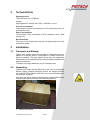
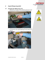
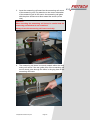
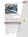
Operating Instructions
Laser Particle Sizer
"ANALYSETTE 22"
MicroTec plus
Fritsch GmbH
Milling and Sizing
Industriestrasse 8
D - 55743 Idar-Oberstein
Phone:
Fax
Email:
URL:
(+49) 6784/ 70-0
(+49) 6784/ 70-11
[email protected]
http://www.fritsch-laser.com
Fritsch GmbH, Laborgerätebau is certified by the TÜV Zertifizierungsgemeinschaft e.V. under certificate registration no. 71
100 4 008
Based on an audit report, Fritsch GmbH has been awarded the
certificate of compliance with the requirements of DIN EN ISO
9001:2000.
The enclosed conformity declaration specifies the directives fulfilled by the laser particle sizer "analysette 22 MicroTec plus" in
order to carry the CE symbol.
MicroTec plus model numbers:
22.8400.00
22.8500.00
Applicable as of serial number 0001
Version 03/2009 Index 000
Created
Inspected and approved
Table of Contents
Page
1 Safety Instructions and Use .............................................................................................1
1.1
1.2
1.3
1.4
1.5
General Information .....................................................................................................................1
Use ..............................................................................................................................................1
General ........................................................................................................................................1
General Safety Instructions .........................................................................................................2
Device Safety Instructions ...........................................................................................................4
1.5.1 Laser ...............................................................................................................................................4
1.5.2 Ultra-Sound Bath.............................................................................................................................5
1.6 Operators.....................................................................................................................................5
1.7 Safety Equipment ........................................................................................................................5
1.8 Electrical Safety ...........................................................................................................................5
1.8.1 General ...........................................................................................................................................5
1.8.2 Overload Protection.........................................................................................................................5
2 Technical Data ................................................................................................................... 6
3 Installation.......................................................................................................................... 6
3.1
3.2
3.3
3.4
3.5
Transport and Storage.................................................................................................................6
Unpacking....................................................................................................................................6
Setup ...........................................................................................................................................9
Accessory Case.........................................................................................................................10
Electrical Connection.................................................................................................................11
3.5.1 Electrical Fuses .............................................................................................................................11
3.5.2 Stability of the Power Supply.........................................................................................................11
3.5.3 Adapting to the Power Network .....................................................................................................11
3.6 Connections...............................................................................................................................12
3.6.1 Measuring Unit Connections .........................................................................................................12
3.6.1.1 Mains Connection ...........................................................................................................12
3.6.1.2 Connecting the Dispersing Unit .......................................................................................12
3.6.2 Liquid Dispersing Unit Connections...............................................................................................13
3.6.2.1 Mains Connection ...........................................................................................................13
3.6.2.2 Installing Hose Connections............................................................................................14
3.7 Preparing the Computer ............................................................................................................14
3.7.1 Installation of the Driver Software..................................................................................................15
3.8 Checking the Communication....................................................................................................18
4 Liquid Dispersing Unit ....................................................................................................19
4.1
4.2
4.3
4.4
4.5
4.6
Changing the Measuring Cell ....................................................................................................19
Changing a Hose .......................................................................................................................21
Selection of the Liquids .............................................................................................................21
Dispersion of Hydrophobic Samples .........................................................................................23
Measurement of Weakly Soluble Samples................................................................................23
The Measuring Cell ...................................................................................................................23
5 Cleaning............................................................................................................................ 24
5.1 Cleaning the Devices.................................................................................................................24
5.2 Cleaning the Measuring Cell .....................................................................................................24
5.2.1
5.2.2
5.2.3
5.2.4
Preparation....................................................................................................................................24
Emptying the System ....................................................................................................................24
Disassembling the Measuring Cell ................................................................................................24
Cleaning the Windows...................................................................................................................27
5.2.4.1 Loose Window.................................................................................................................27
5.2.4.2 Fixed Window..................................................................................................................28
5.2.5 Flow Disk.......................................................................................................................................28
5.2.6 Seal Rings.....................................................................................................................................28
5.2.7 Installing the Measuring Cell .........................................................................................................28
"analysette 22" MicroTec plus
Table of Contents
Page
5.3 Filling the Measuring Cell ..........................................................................................................29
5.3.1 Liquid Dispersing Unit ...................................................................................................................29
5.3.2 When Using the Small Quantity Dispersing Unit ...........................................................................29
6 Accessories...................................................................................................................... 30
6.1 "MaScontrol" Software Package................................................................................................30
6.2 Small Quantity Dispersing Unit..................................................................................................30
6.2.1 Connecting the Small Quantity Dispersing Unit.............................................................................30
6.2.2 Manual Changing of the "Liquid" Measuring Cell for the Small Quantity Dispersing Unit ..............31
7 Maintenance ..................................................................................................................... 31
8 Warranty ........................................................................................................................... 32
9 Troubleshooting ..............................................................................................................32
9.1 Error List ....................................................................................................................................32
9.2 Transferability of Measurement Results....................................................................................32
10 Disclaimer......................................................................................................................... 33
"analysette 22" MicroTec plus
1
Safety Instructions and Use
1.1
General Information
These operating instructions are intended for persons who are
charged with the operation and supervision of Fritsch laser particle sizers. All operators must be familiar with the contents of the
operating instructions. For this reason, it is very important that
these operating instructions actually be provided to these persons. It must be ensured that the operating instructions always
remain within easy reach of the instrument.
Fritsch has prepared and inspected these operating instructions
with great care. Nevertheless, no warranty can be made regarding the completeness or absence of errors.
All commissioning, maintenance and repair work may only be
performed by qualified personnel!
Subject to technical changes.
1.2
Use
The laser particle sizer ANALYSETTE 22 MicroTec plus is a universally usable instrument for determination of the particle size
distribution of suspensions, emulsions and solids. It is primarily
used in research and development and in quality and process inspections.
The ANALYSETTE 22 MicroTec plus makes use of the FRITSCH
patent on a positionable measuring cell in a convergent laser
beam for determination of the particle size distribution.
The laser particle sizer described here is a system for use in an
industrial environment. During operation, parts of the system exhibit dangerous current levels and laser radiation sources. As a
consequence, unauthorised removal of required covering elements or insufficient maintenance can result in serious injuries or
material damages.
1.3
General
Fritsch GmbH, Laborgerätebau retains the copyright to these
technical documents. These operating instructions are not to be
reprinted or copied without the express approval of Fritsch
GmbH.
The laser particle sizer was designed from the perspective of
user safety, however some risks could not be excluded. Follow
the instructions given here to avoid risks to users.
The symbols in the right hand margin highlight the risks described in the text. Some symbols are also found on the device
and warn against possible hazards existing there. Warning symbols are surrounded by a triangle.
These operating instructions do not constitute a complete technical description. They describe only the details required for safe
operation and maintenance for usage under normal conditions.
"analysette 22“ MicroTec plus
Page 1
1.4
General Safety Instructions
The following symbols are used in this description to refer to important information and possible dangers.
Caution!
Warning against a danger source
Follow the operating instructions
Caution!
Mains voltage
Caution!
Risk of explosion
Caution!
Inflammable substances
Caution!
Warning against laser beam!
Wear safety goggles!
Spraying with water forbidden!
Warning against hand injury!
"analysette 22“ MicroTec plus
Page 2
•
•
•
•
•
•
•
•
•
•
•
Read the operating instructions carefully.
The device may only be used for the purpose described
above.
Do not remove the instruction labels
Care must be taken to prevent accidents during all work.
Independent conversions of the device negate the conformity
with European directives declared by Fritsch and void the
warranty..
When measuring oxidisable substances, such as metals, organic substances, wood, coal, plastics, etc., the risk of spontaneous combustion (dust explosion) exists if the fine portion
exceeds a certain percentage. For this reason, special safety
measures (e.g. measurement in suspension) must be taken
and the work must be supervised by a specialist.
In addition, the maximum workplace concentration values of
the pertinent safety regulations must be observed, and sufficient ventilation must be ensured or the device must be operated under a hood.
The device is not designed with explosion protection and is
not suitable for measuring explosive, combustible or firepromoting substances.
The device may not be used in an electrically conducting,
dust-containing or moist environment.
Do not allow any liquids to enter the device.
Do not use any highly flammable, burnable liquids such as
alcohols, ketones, benzines, etc.
"analysette 22“ MicroTec plus
Page 3
1.5
Device Safety Instructions
1.5.1 Laser
The measurement unit of the ANALYSETTE 22 MicroTec plus
contains two semiconductor lasers, each with 7 mW output and a
wavelength of 532 nm or 940 nm. Accordingly, when removed
from the housing or if the housing itself is removed, the lasers of
the ANALYSETTE 22 MicroTec plus are classified as Class 3b
EN 60825-1/11.2001, and the laser emitters may only be operated under the purview of the safety regulations of the German
Trade Supervisory Office if the corresponding safety instructions
of EN 60825 Part 1 and 2 are observed. The user must familiarise himself with the hazards involved with laser emitters before
using the device. Laser devices of laser classes 3B and 4 are
hazardous to the human eye; even an exposure time of 0.25 s is
sufficient to cause permanent damage to the retina. For this reason, any person operating the device with opened housing must
wear suitable safety goggles. The safety goggles must be suitable for the wavelength of the lasers used.
Warning labels regarding the laser emissions are located on the
side parts of the device.
WARNING:
• Never look into the laser beam.
• Never place reflective objects within the laser beam.
• Wear appropriate safety goggles during maintenance or
calibration work on the open laser emitter. (< 10 mW, 532 and
940 nm).
• The device equipped with a laser emitter may only be operated by authorised personnel.
• The user of the device must familiarise himself with the
hazards involved with laser emitters before using it.
• Do not remove information and warning signs.
Appointing of a laser safety officer for the ANALYSETTE
22 is not necessary since the emission sources are fully enclosed and inaccessible as with a laser printer or DVD
player.
The ANALYSETTE 22 MicroTec plus is classified according
to EN 60825 under laser safety class 1.
Important:
The laser is automatically deactivated upon removal of the measuring cell insert.
"analysette 22“ MicroTec plus
Page 4
1.5.2 Ultra-Sound Bath
The ultra-sound bath built into the liquid dispersing unit has an
output of up to 50 watts. PZT ultra-sound oscillators fastened to
the oscillating trough convert electrical energy into mechanical
vibrations. Fritsch ultra-sound baths cause the liquid to vibrate at
40 kHz. This causes miniscule vacuum bubbles that implode.
This cavitation principle destroys agglomerations.
Liquids contain dissolved gasses (e.g. oxygen). Freshly added liquids or liquids remaining in the oscillating trough for longer periods of time should be exposed to ultra-sound for approx. 5 to 15
minutes before use. During the degassing period, the cavitation
noise alters, loud degassing noises disappear at the end of the
degassing process, the device operates noticeably more quietly.
A lower noise level does not mean any subsiding in the ultrasound output, only the end of the degassing process.
WARNING!
• Do not operate the ultra-sound bath without liquids.
• Do not use any flammable liquids (e.g. benzine, solvents) and
no chemicals that contain or give off chloride ions (some disinfectants, household cleaners and dishwashing soaps) for dispersion in the stainless steel trough. If working with flammable
liquids is indispensable, the liquid may under no circumstances be exposed to ultra-sound and the smallest possible
volume of liquid should be used. See section 4.3 Selection of
the Liquids.
• Do not use aggressive liquids (e.g. acids, salt solutions).
• Do not reach into the liquid during ultra-sound emission.
• The liquid heats up during longer periods of operation; check
the temperature.
1.6
7
Operators
The device may only be operated by authorised persons and
maintained and repaired by trained experts.
Persons under the influence of health impairments, medications,
drugs, alcohol or excess fatigue may not operate the device.
1.7
Safety Equipment
Safety equipment such as coverings must be used as instructed
and may not be disabled or removed.
1.8
Electrical Safety
Connect the measuring device to a power supply line protected
with a residual current circuit breaker.
1.8.1 General
The power switch disconnects the machine from the supply at
both poles.
1.8.2 Overload Protection
The power supply protection provides overload protection.
"analysette 22“ MicroTec plus
Page 5
7
2
Technical Data
Operating noise
The noise level is LpA<70dB(A).
Voltage
Single-phase AC voltage 100-120 V / 200-240 V ± 10%.
Current consumption
The maximum current consumption is 0.2 A (measuring unit), 0.4
A (dispersing unit)
Power consumption
The maximum power consumption is 50 W (measuring unit), 100W
(supply unit).
Electrical fuses
Two fuses of 2 A (measuring unit) and 4 A (dispersing unit) in the
connection socket
3
Installation
3.1
Transport and Storage
Fritsch laser particle sizers are shipped in cardboard boxes on
pallets or in wooden crates. These pallets or crates may not be
tipped or stacked. The laser particle sizers must be transported
and stored in their packaging and protected against weather and
external influences.
Transport over larger distances only in a transport box.
3.2
Unpacking
Compare your order with the delivery! In the event of incomplete
delivery and/or transport damages, inform the shipper immediately and FRITSCH GmbH within 24 hours. Later complaints can
no longer be accepted.
Only open the boxes while the arrows point upward! Remove the
transport packaging as shown in the following pictures.
1.
Remove the top lid.
"analysette 22“ MicroTec plus
Page 6
2.
The accessory case is located beneath the lid. Remove the
case.
3.
Remove the top foam parts.
"analysette 22“ MicroTec plus
Page 7
4.
Lift the measuring unit and liquid dispersing unit out of the
moulded foam as shown in the image. This action requires
two people.
Warning:
The top grips are not transport grips; they are intended only
for lifting out the measuring cell insert.
"analysette 22“ MicroTec plus
Page 8
3.3
Setup
Place the device indoors on a flat, stabile surface. It is not necessary to fasten the device in place.
Please avoid intense heat (sunlight, heaters, etc.), dusty environments and their effects on the interior of the measuring device
as well as extreme humidity (>85%).
The permissible ambient temperature during operation of the device is 10°C to 35°C. Storage between 1°C and 40°C is possible.
If it is expected that the temperature will fall below the permissible temperature range (e.g. for a planned transport), it is essential that the entire suspension circuit (dispersing unit, hoses and
measuring cell in the measuring device) first be rinsed thoroughly
with ethanol and the liquid then completely removed.
The device may not be switched on while cooled below the permissible temperature. After the device has been cooled to temperatures below 10°C, you must wait for the device to warm to
ambient temperature before switching it on; condensation in the
device can lead to disruptions and damage.
You will be able to see characters and graphics on the screen
more easily if you select a setup location such that sunlight or artificial light do not fall directly on the image tubes. Sometimes
simply turning the monitor "out of the light" will help; partial shadow increases the contrast and helps to prevent eye fatigue.
Easy accessibility should be ensured during setup so the device
can be operated without difficulty.
The setup location must be protected against water. If there exists the risk that a water layer could form on the setup surface in
the event of an error, you must select another setup location. If
no other location is available, the entire device must be elevated
(use riser blocks).
"analysette 22“ MicroTec plus
Page 9
3.4
Accessory Case
The accessory case contains materials and tools for cleaning of
the optical glass elements (cleaning fluid, cleaning cloths, compressed air, etc.), replacement screws, hose clips and seals for
the measuring cell, tools for assembly and maintenance, a DVD
with software, a microfibre cleaning cloth for metal and glass surfaces, internal particle size standards F500, F70, dispersion
agents, USB cable, power cord and communication cable.
A packing list is enclosed with the case.
"analysette 22“ MicroTec plus
Page 10
3.5
Electrical Connection
Connect the measuring device, the dispersing unit, the computer
with monitor and the printer to a power strip each with separate
power cables.
Important:
Connect the power strip to a power supply line protected
with a residual current circuit breaker.
3.5.1 Electrical Fuses
The measuring and dispersing units each have two device fuses
in the power connection sockets.
3.5.2 Stability of the Power Supply
Devices with electronic components demand stabile supply voltages (+/- 10% deviation). For weak power networks or networks
not safe against errors (voltage peaks due to inductive load
changes or switched-mode power supplies), we recommend
connecting a voltage stabiliser and filters between the power
supply and device (order no. 20.6000.00).
3.5.3 Adapting to the Power Network
Manual switching of the voltage ranges on the device is not necessary because the device can be operated with 100-120 V /
200-240 V. The switching is performed automatically.
"analysette 22“ MicroTec plus
Page 11
3.6
Connections
Important:
Install the USB driver software before switching on the MicroTec
plus for the first time. (See section 3.7.1 Installation of the Driver
Software)
Only connect the USB cable between the device and the computer after installing the driver software.
3.6.1 Measuring Unit Connections
The following connections are located on the back side of the
measuring unit:
Item 1: Connections for connecting the dispersing units to the
measurement unit
Item 2: USB port for connecting the measuring unit to the computer
3
4
Item 3: On/off switch
Item 4: Power socket
3.6.1.1 Mains Connection
Connect the supplied power cord to the main power supply (4).
Before connecting the device to your mains network, set the
on/off switch to 0, then proceed as described in section 3.5.
3.6.1.2 Connecting the Dispersing Unit
Connect the measuring unit to the liquid dispersing unit using the
supplied data cable. Plug the cable into one of the connections
provided (1) on the back side of the measuring unit. Insert the
other end into the socket provided on the back side of the liquid
dispersing unit.
"analysette 22“ MicroTec plus
Page 12
3.6.2 Liquid Dispersing Unit Connections
The following connections are located on the back side of the
liquid dispersing unit:
1
2
3
7
4
5
8
6
Item 1: On/off switch
Item 2: Power socket
Item 3: Measuring unit connection
Item 4: External pump connection
Item 5: Suspension liquid discharge
Item 6: Suspension liquid supply (IMPORTANT: max. 0.8 bar )
Item 7: Measuring cell supply
Item 8: Measuring cell discharge
3.6.2.1 Mains Connection
Connect the supplied power cord to the main power supply (4).
Before connecting the device to your mains network, set the
on/off switch to 0, then proceed as described in section 3.5.
"analysette 22“ MicroTec plus
Page 13
3.6.2.2 Installing Hose Connections
Caution!
Lay all hoses without kinks.
The hose connections must be connected pressure-tight with
hose clamps.
The filling connection labelled "Liquid In" (6) is used for filling of
the measuring apparatus. Connect the filling connection to your
building water supply via the supplied pressure reducer and hose.
Secure the hose to the filling connection using the supplied hose
clip.
The pressure reducer is permanently set to 0.8 bar.
In order to ensure that the rinsing process can be completed
properly, you must therefore provide at least 2 bar from your
water supply.
If you connect the "Liquid In" filling connection (6) with demineralised, filtered water or a liquid reserve reservoir tank, you can connect an external filling pump to the "External Pump" connection
(4); the pump will then be switched on and off according to when
the device requests water. The following accessories are required
for connection of the pump: 86.5500.00 power supply switch box,
22.1870.00 switch box cable.
The drain connection (5) labelled with "Drain" is used to discharge used measuring and rinsing liquid from the drain valve.
For drainage, use a hose for used suspension fluid with 20 mm
internal diameter and secure it to the drain connection with the
supplied hose clip.
Run the drain hose to the drain of a washbasin or a special collection container for your suspension.
Caution!
The measuring and rinsing liquid is pumped out of the drain
hose with pressure during the rinsing process. Make certain
that the hose cannot slide out of the drain or collection container to cause spillage.
3.7
Preparing the Computer
The MicroTec plus contains an integrated serial to USB converter
that makes it possible to connect the MicroTec plus to an analysis computer via a USB port.
This converter requires driver software that is found on the supplied Fritsch DVD. The installation program is located in the directory prg\USB driver MicroTec plus\PL-2303 Driver Installer.exe .
Current drivers can also be found on the homepage of prolific:
www.prolific.com.tw in the area Support / Download / USB
and Firewire.
Important:
Install the USB driver software before switching on the MicroTec
plus for the first time.
"analysette 22“ MicroTec plus
Page 14
3.7.1 Installation of the Driver Software
1.
Run the file PL-2303 Driver Installer.exe.
2.
Click on NEXT.
3.
Accept the license agreement and click on NEXT.
4.
Continue installation.
"analysette 22“ MicroTec plus
Page 15
5.
Complete the installation with FINISH.
Connect the measuring unit (which has a USB port in the rear) to
a USB port of your computer using the supplied USB cable.
Use the main power switches located on the upper rear of each
device to switch on first the liquid dispersing unit and then the
measuring unit.
The wizard for locating new hardware opens automatically.
1.
Select "NO, NOT THIS TIME“ Æ "NEXT"
"analysette 22“ MicroTec plus
Page 16
2.
Select "AUTOMATICALLY INSTALL SOFTWARE" Æ Next
3.
"CONTINUE INSTALLATION"
4.
"FINISH"
"analysette 22“ MicroTec plus
Page 17
5.
3.8
In Windows, click on the button "START"/"CONTROL
PANEL"/"SYSTEM"/"HARDWARE"/"DEVICE MANAGER“.
The ports of the Prolific USB-to-serial-communication port
are shown there.
Make note of the COM port that was assigned by Windows
and select this port in the "MaS control" software.
Checking the Communication
After the USB connection between the measuring device and the
computer has been established, you must check the communication. Select MicroTec plus and the appropriate COM port in the
configuration menu.
Select "Start Measurement" and the SOP with the name "Function Test". Press OK.
Now perform a measurement with the Fritsch internal standard
sample. Instructions for this can be found in the Fritsch reference
manual.
"analysette 22“ MicroTec plus
Page 18
4
Liquid Dispersing Unit
4.1
Changing the Measuring Cell
1.
Remove the cover plate of the measuring cell mount on the
measuring unit and place it next to the liquid dispersing unit.
2.
Carefully remove the measuring cell insert from the measuring cell mount of the liquid dispersing unit by pulling it out
upwards.
"analysette 22“ MicroTec plus
Page 19
3.
Insert the measuring cell insert into the measuring cell mount
of the measuring unit. Pay attention to the correct orientation
of the measuring cell in the mount: the measuring cell glass
with the prism surface must face toward the sensor (to the
rear).
Attention:
When inserting the measuring cell insert, be careful that the
measuring cell window is not scratched.
Always insert the measuring cell insert vertically.
4.
The measuring cell insert is correctly seated within the measuring cell mount if the two guide pins of the measuring cell
mount clearly pass through the holes in the grip plate of the
measuring cell insert.
"analysette 22“ MicroTec plus
Page 20
5.
4.2
Close the measuring cell mount of the liquid dispersing unit
with the cover panel.
Changing a Hose
If it is necessary to change a sample hose, pay attention to the
labels "To Cell" and "From Cell" on the back side of the liquid
dispersing unit and on the measuring cell insert. Only connect together connections with the same label.
4.3
Selection of the Liquids
The measuring liquid in the device (supply and measuring unit)
only comes into contact with materials that are largely chemically
resistant. Certain organic liquids or saturated inorganic salt solutions may be used briefly without damaging the device.
The measuring liquid comes into contact with stainless steel,
glass, PTFE, Viton (FPM and FKM) and Norprene A-60-G. The
standard connection hoses are made of Norprene A-60-G.
Fritsch GmbH recommends water as the suspension liquid
for the dispersing unit.
For measurement of samples incompatible with water, an appropriate liquid may be selected from the following list (see also the
Compatibility List section):
• Mono-, di- or tryhydric alcohols (except for methanol), e.g.
ethyl alcohol, isopropyl alcohol, glycol or glycerine
• Benzines (petroleum ether, test benzine, kerosine),
• Mineral and organic oils such as petroleum and soy oil, nut
oil, olive oil
• Cyclic aromatic compounds / ring hydrocarbons (toluene only
briefly - rinse out after the measurement)
• Alkanes
• (Hexane, heptane only briefly - rinse out after the measurement because the connecting hoses will be damaged.)
• Formaldehyde
• Saturated solutions of inorganic salts
"analysette 22“ MicroTec plus
Page 21
Samples present in oil (e.g. oils similar to machine oil) do not also have to be measured in oil.
Example: Toner in machine oil
The sample is first dispersed in ethylene glycol with a drop of
tenside (Pril) in the ultra-sound bath. Then a mixture is created
1:1 with water, and this is added to the ultra-sound bath of the laser particle sizer ANALYSETTE 22.
Example: Raw cocoa mixture
Raw cocoa mixture is typically measured in acetone or benzine
(known from the sieving process). Measurement in the
ANALYSETTE 22 can also be performed in peanut oil, for instance. Because peanut oil is suitable for use with food, the
waste oil can also be used as a lubricant on the rollers, solving
the disposal problem.
Example: Weakly magnetic materials
In general, particle size distributions of magnetic substances
cannot be measured in suspensions due to the mutual attraction
of the individual particles. However, due to the high sensitivity of
the ANALYSETTE 22, very low concentrations - in other words
relatively large distances between the individual particles - can
be used on one hand, and on the other, substances can also be
suspended with high viscosity liquids due to the high power of the
centrifugal pump.
If larger particles or particles with higher density must be measured, the share of glycerine can be increased up to a ratio of 7:3.
In general, liquids up to a viscosity of 30 cPoise can still be pumped without problems by the pump system of the dispersing unit.
Before the planned use of other measuring liquids, Fritsch
GmbH must first be consulted.
In principle, we warn against the use of liquids that are explosive, combustible or hazardous to health - they cannot be
recommended.
The summary given above is intended only to provide information about the chemical compatibility of the device with
respect to liquids.
The measuring device and dispersing units are not designed
with explosion protection.
The following may not be used:
Ketones (acetone, propanone, butanone, cyclohexanone),
Ether, fluorochlorohydrocarbons,
Amines, freon 21-32, methanol, aniline, benzine
Chlorohydrocarbons such as ethanoic acid and their derivitives, undiluted acids and bases.
"analysette 22“ MicroTec plus
Page 22
8
When using measuring liquids hazardous to health, always
follow the applicable safety regulations (maximum workplace concentration values) and place the measuring unit
and dispersing units in ventilated safety zones if required.
The liquid consumption is significantly reduced through the use of
the small quantity dispersing unit.
4.4
Dispersion of Hydrophobic Samples
Hydrophobic samples can be dispersed despite their waterrepulsing properties if they are first mixed into a paste with a fluid
tenside (Pril) and then dispersed in water under constant stirring.
Agglomerates are also dispersed more easily and more quickly in
an ultra-sound bath because the entire sample is subjected to the
ultra-sound. In the circuit of the dispersing unit, only the quantity
in the bath is in the area of the ultra-sound.
For soil samples, 0.1 - 0.5% sodium pyrophosphate solution is
recommended as a dispersing aid, for example. The sample prepared in this way in an ultra-sound bath (e.g. "laborette 17" can
be measured in pure water.
4.5
Measurement of Weakly Soluble Samples
Even samples that are weakly soluble in liquid can be measured
with the laser particle sizer ANALYSETTE 22. To do this, preparation of a saturated measuring liquid is recommended. In this liquid, the particle size cannot change by dissolving - the measurement results therefore remain inaccurate. (However, the saturated solution must be filtered before use.)
For very expensive products, it is sometimes worthwhile to identify a replacement substance that takes over the task of "saturating" the measuring liquid.
4.6
The Measuring Cell
The measuring cell has angled surfaces on the side facing the
detector so that light can leave the measuring cell even with large
diffraction angles. The window on this side is firmly attached to
the rear measuring cell flange of the measuring cell. The opposite window is loosely inserted into the slot in the front measuring
cell flange and can be removed for cleaning.
"analysette 22“ MicroTec plus
Page 23
5
Cleaning
5.1
Cleaning the Devices
The devices can be cleaned with a damp cloth or a microfibre
cloth from the accessory case.
Do not allow any liquids to flow into the devices.
5.2
Cleaning the Measuring Cell
It is normally sufficient to rinse the measuring cell with a clear liquid. To remove stubborn residues, you can also add a cleaning
agent to the cleaning liquid. Generally a few drops of a surfaceactive household cleanser (e.g. Pril™ or liquid soap) are sufficient.
Mechanically adhering contamination can be rinsed out with the
addition of approx. 2 g of fine abrasive. (Household abrasives
ATA™, VIM™,....). Oily residues can be rinsed out with a slightly
alkaline cleaning agent.
The word "window" is used below to refer to the glass elements
of the measuring cells.
5.2.1 Preparation
Lay out the following:
• Tool for cell disassembly
• Spatula
• Cleaning agent
• Lens cleaning paper
• Clean paper towels
• Spray bottle with distilled water
Assemble the tool for disassembly of the measuring cell.
5.2.2 Emptying the System
In the program, select "Device Controller" Æ "Drainage“ Æ "Open
both“ Æ "Set“. The liquid in the system then drains out.
5.2.3 Disassembling the Measuring Cell
Although the measuring circuit should now be completely without
liquid, it may be that residual liquid remains in the measuring cell
itself. Therefore, you should have a paper towel or something
similar ready to directly collect any liquid escaping.
"analysette 22“ MicroTec plus
Page 24
9
9
1.
Lift the measuring cell insert out of the measuring unit and
lay it on a prepared piece of paper towel.
2.
Open the 4 screws that close the measuring cell in a crosswise pattern.
3.
Lift off the "rear" measuring cell flange with the glued in window.
"analysette 22“ MicroTec plus
Page 25
4.
Lay the "rear" flange onto a paper towel with the window
(prism) facing up.
5.
Remove the outer O-ring and clean the metallic surfaces of
the "front" flange.
6.
Lift up the measuring cell mount and press the window of the
"front" flange out of the measuring cell using a clean paper
towel. Place the loose window on the lens cleaning paper
with the outside facing down.
Caution !!!
Do not catch the edges of the window when pressing it out. This
could destroy the glass edges.
Lodged particles may make the window somewhat difficult to remove.
Attempt to tilt it somewhat within the frame when pressing it out
by pressing on one side or the other.
The windows may only be touched by hand on their edges.
"analysette 22“ MicroTec plus
Page 26
7.
Lift the flow disk out of the "rear" flange using a spatula,
being careful not to touch the measuring cell window.
Caution:
NEVER lay the "rear" flange of the measuring cell on an unprotected surface with the window facing down. This could
scratch the optical glass or destroy the anti-reflex coating.
This can make your entire measuring cell unusable.
5.2.4 Cleaning the Windows
Great care is required for cleaning the windows. The windows
may only be touched by hand on their edges.
5.2.4.1 Loose Window
The following window cleaning method has proven successful:
Rinse the window using the spray
bottle of distilled water until no large
contamination is visible. Then lay the
special paper on the inside of the
window and moisten it with distilled
water and a drop of tenside (Pril) so
that the paper sticks to the glass surface.
To "wipe off" the surface, slide the
paper off parallel to the surface without pressing the paper against the
glass.
"analysette 22“ MicroTec plus
Page 27
You may need to repeat this wiping process on the glass surface
with fresh paper until contamination can no longer be seen.
Sample residue that adheres very strongly can be "softened" with
a tenside (e.g. Pril™) and very carefully wiped a little with the
special paper.
Then rinse the window clean with the spray bottle and dab it off
carefully onto the dry special paper. You should carefully keep
the window covered until it is installed again in the measuring
cell.
5.2.4.2 Fixed Window
The same applies to the window attached in a fixed position to
the "rear" flange as for the loose window. Handle the optical surfaces very carefully.
Also clean all metal surfaces and seals very well. Adhering grains
can lead to the window not being optimally installed and the laser
beam is brought out of calibration by moving of the measuring
cell. In extreme cases, a glass can even break during installation.
5.2.5 Flow Disk
The flow disk is made of PTFE and must be handled carefully! It
must never be subjected to mechanical loads. A bent flow disk
cannot be used. You can rinse the flow disk under flowing water.
Brush off any adhering particles very carefully with a soft brush.
5.2.6 Seal Rings
The seal rings can be rinsed under flowing, particle-free (distilled)
water and then dried with lint-free, soft paper.
5.2.7 Installing the Measuring Cell
After cleaning the parts, you must reassemble the measuring
cell.
Assembly of the measuring cell is performed in reverse order:
Lay in the loose window with the bluish shimmering anti-reflex
coating facing out (there are arrows on the window edges, see
image, the arrows point out, toward the anti-reflex coating).
You can identify the anti-reflex layer
by holding a window at an angle to a
fluorescent lamp. If you see the inner
border of the window shimmer in a
bluish colour, the reflex layer is facing up. The coated side is also marked with an arrow on the edge
of the glass.
If the inner border appears whitish, the reflex layer is facing down
because the light entering into the window does not appear coloured by the anti-reflex layer. Then lay the seal ring into the
groove provided for this.
"analysette 22“ MicroTec plus
Page 28
Lay the flow disk into the rear flange. Then carefully join the two
halves of the measuring cell. The screws must be tightened carefully in a cross pattern.
You must take care that you "close" the two halves evenly with
the four screws. The flow disk situated between the two windows
holds the windows in an exactly parallel position. Any contamination remaining between the windows and the flow disk must
absolutely be removed first. A particle remaining between a window and the flow disk can lead to breaking of a window when
screwing the cell together! It also prevents the windows from being perfectly parallel.
If the windows are not parallel, the calibration of the laser beam
is disrupted. (The calibration is no longer valid for the entire adjustment range of the measuring cell due to the prism effect of
the unparallel measuring cells.)
Do NOT tighten any screw all at once! Turn the screws a little
tighter in alternation until all screws are tight. If you tighten the
screws unevenly, the windows may break.
5.3
Filling the Measuring Cell
5.3.1 Liquid Dispersing Unit
Leave the measuring cell laying on a paper towel for now and inspect the measuring cell for gaps in the seal.
Select the measurement process "Rinse Before Measurement"
and press "Start Measurement". The ultra-sound bath then rinses
itself and fills itself with clear measuring fluid. The fill level sensor
automatically closes the valve.
5.3.2 When Using the Small Quantity Dispersing
Unit
Emptying and filling of the small quantity dispersing unit is performed manually.
Turn the valve lever to "Drain/Fill". With the supply opened, fresh
suspension liquid then flows into the glass container through the
connected "In" hose. The liquid level rises while the pump is
switched off.
"analysette 22“ MicroTec plus
Page 29
6
Accessories
6.1
"MaScontrol" Software Package
All functions of the MicroTec plus can be programmed and controlled using the "MaScontrol" software package (see the MaScontrol user manual).
6.2
Small Quantity Dispersing Unit
6.2.1 Connecting the Small Quantity Dispersing
Unit
The small quantity dispersing unit is delivered with a special liquid measuring cell. The dispersing unit has four hose connections labelled with:
• "FROM CELL"
• "TO CELL"
• "IN"
• "OUT".
"FROM CELL" and "TO CELL" are connected to the measuring
cell insert.
Connect the hose with the red
marking with Æ to cell
"IN" on the dispersing unit serves to fill the measuring apparatus
and is connected either to a central supply line with, for instance,
demineralised, filtered water, or to a storage tank with measuring
fluid.
"OUT" serves to discharge the measuring and rinsing fluid.
"analysette 22“ MicroTec plus
Page 30
The hoses are firmly connected on delivery. Should it ever be
necessary to replace the hoses, connect "FROM CELL" with the
hose connection of the measuring cell insert that is labelled as
"From Cell". Connect "TO CELL" to the other connection of the
measuring cell correspondingly labelled "To Cell". The measuring
liquid flows into the measuring cell from bottom to top.
Important:
The maximum water pressure in the device is 0.5 bar !
6.2.2 Manual Changing of the "Liquid" Measuring
Cell for the Small Quantity Dispersing Unit
The following steps must be followed to switch the device to the
small quantity dispersing unit:
1. Remove the measuring cell insert of the normal liquid dispersing unit.
2. Place the small quantity dispersing unit next to the measuring unit.
3. Position the measuring cell insert of the small quantity dispersing unit in the measuring cell mount of the measuring
unit.
7
Maintenance
The analysette 22 NanoTec and MicroTec requires no maintenance apart from the regular cleaning.
Before starting any work in the device, switch off the measuring unit and the liquid dispersing unit and unplug the
power cord!
"analysette 22“ MicroTec plus
Page 31
8
Warranty
The warranty card enclosed with the device upon delivery must
be completely filled out and returned to the delivering factory so
that the warranty can enter into effect. The company FRITSCH
GmbH Laborgerätebau, Idar-Oberstein and its "Technical Application Laboratory" or the corresponding national representatives
will be glad to offer advice and assistance.
Indication of the serial number imprinted on the type plate is required with any questions. The type plate is located on the back
side of the liquid dispersing module and measuring module.
9
Troubleshooting
9.1
Error List
9.2
Error
Possible Cause
Remedy
Light
does not light
up
Power connection
missing
Plug in the power plug
Main switch
Switch on the main switch
Mains fuse
Replace the mains fuse
Transferability of Measurement Results
If a measurement of particles is intended to determine which of
their assumed properties are true, the measurer is not only an
observer and the measuring device is not only his tool; rather,
both participate actively in the process. In the determination of
particle size distributions, both are active in generating the result
and determining its nature.
In the development of measuring devices, the designer strives to
eliminate the influence of the operator as much as possible. However, the effects of the physical measurement process applied
and its realisation in the device cannot be ignored.
If, for example, particle size distributions are measured according
to the sedimentation process (scanning photo sedimentograph
"analysette 20") and through analysis of a diffraction image, at
least slightly deviating results must be expected.
In the measurement of particle sizes through the analysis of a diffraction image, all dimensions of irregular particles are "seen"
and correspondingly taken into account in the result. For instance, the longitudinal extent of needle-shaped samples is also
determined here. In a comparison or the transfer of particle size
distributions from various measuring processes, the particle shape must be taken into consideration.
"analysette 22“ MicroTec plus
Page 32
10
Disclaimer
Prior to using this product, this manual must be carefully read
and understood. The use of this product requires technical knowledge and may only be used by commercial users. The product
may only be used for the applications shown and instructions given within the scope of this manual and must be maintained on a
regular basis. In case of non-compliance or improper maintenance of the product, the customer shall be fully responsible for
the functionality of the product or shall be liable for any damages
or injuries resulting from the violation of this responsibility.
This manual was produced to the best of our knowledge and its
up-to-datedness was checked at the time of print. FRITSCH
GMBH does not provides no guarantee of the correctness or
completeness of the content of this manual, including but not limited to implicit guarantees pertaining to the market suitability and
the suitability for certain purposes, unless applicable laws or legislation call for a compulsory liability.
FRITSCH GMBH further reserves the right to revise and/or update the manual without prior notice. The same shall apply to revisions or improvements to any products described in this manual. It is the responsibility of the individual user to inquire about
the latest issue of this manual. In this regard, please contact your
local FRITSCH GMBH sales partner or Fritsch GmbH, Industriestr. 8, D-55473 Idar-Oberstein.
Not all components shown in this manual may be part of the product. The purchaser does not have any claim to delivery of these
parts. If interested, please contact your local FRITSCH GMBH
sales partner or Fritsch GmbH, Industriestr. 8, D-55743 IdarOberstein.
FRITSCH GMBH strives to continuously improve the quality, reliability and safety of this product and to maintain the product's
state-of-the-art design. At the time this product and the accompanying manual left the sphere of influence of FRITSCH GMBH,
it satisfied current technological standards and practices.
When using this product, the customer agrees and acknowledges
that defects, malfunctions or errors are not completely unavoidable. In order to avoid the risk of direct or indirect damages to
persons or property resulting from the facts mentioned above or
any other causes, the customer is required to take sufficient and
adequate preventive measures when working with the product.
"analysette 22“ MicroTec plus
Page 33
Fritsch GmbH rejects all contractual, legal or other liabilities, guarantees or obligations in connection with compensation for damages, whether explicit, implied, contractual or arising due to unauthorised actions. Under no circumstances will Fritsch GmbH be
held liable or grant the right for compensation for specific, direct,
indirect, accidental or consequential damages, including but not
limited to lost financial gains, lost savings, lost circumstances or
financial losses of any kind. This further applies to compensation
for damages to third parties, downtimes, goodwill, damages to or
replacement of equipment or property, costs for the reconstruction of materials or goods in connection with the product, for
damages or injuries to persons (including death) or similar. The
above disclaimer shall apply exclusively unless compulsory liability is stipulated by law or legislation. Liability for negligence shall
be excluded in all cases.
Neither explicit, implied nor any other rights of use pertaining to
patents, trademark or other copyrights are granted. Furthermore,
we shall not be held responsible for any violation of patents or violations of rights to third parties resulting from use of this product.
Fritsch GmbH cannot monitor the adherence to this manual or
the conditions and methods during the installation, operation, application and maintenance of the product. Improper installation
may cause damage to property or endanger people. We cannot
be held responsible for any losses, damages or costs arising
from faulty installations, improper operation as well as incorrect
use and maintenance or any other liability connected with the
above.
"analysette 22“ MicroTec plus
Page 34