1
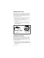
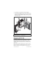
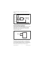
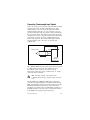
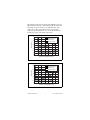
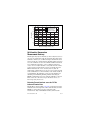
FieldPoint Operating Instructions
FP-TC-120 AND CFP-TC-120
8-Channel Thermocouple Input Modules
These operating instructions describe how to install and use the
National Instruments FP-TC-120 and cFP-TC-120 thermocouple
input modules (referred to inclusively as the [c]FP-TC-120). For
details on configuring and accessing the [c]FP-TC-120 over a
network, refer to the user manual for the FieldPoint network
module you are using.
Features
The [c]FP-TC-120 is a FieldPoint thermocouple input module with
the following features:
•
Eight thermocouple or millivolt inputs
•
Built-in linearization and cold-junction compensation for eight
thermocouple types: J, K, R, S, T, N, E, and B
•
Four voltage ranges: ±25, ±50, ±100, and –20 to 80 mV
•
Open-thermocouple detection and indicator LEDs
•
16-bit resolution
•
Differential inputs
•
Filtering against 50 and 60 Hz noise
•
2,300 Vrms transient overvoltage protection between the
inter-module communication bus and the I/O channels
•
250 Vrms isolation voltage rating
•
–40 to 70 °C operation
•
Hot plug-and-play
FieldPoint™, National Instruments™, NI™, and ni.com™ are trademarks of National Instruments Corporation.
Product and company names mentioned herein are trademarks or trade names of their respective companies.
For patents covering National Instruments products, refer to the appropriate location: Help»Patents in your software,
the patents.txt file on your CD, or ni.com/patents.
373344A-01
October 2002
© 2002 National Instruments Corp. All rights reserved.
Installing the FP-TC-120
The FP-TC-120 mounts on a FieldPoint terminal base (FP-TB-x).
Hot plug-and-play enables you to install the FP-TC-120 onto a
powered terminal base without disturbing the operation of other
modules or terminal bases. The FP-TC-120 receives operating
power from the terminal base.
To install the FP-TC-120, refer to Figure 1 and follow these steps:
1. Slide the terminal base key to either position X (for any
module) or position 1 (for the FP-TC-120).
2. Align the FP-TC-120 alignment slots with the guide rails on
the terminal base.
3. Press firmly to seat the FP-TC-120 on the terminal base.
The latch on the terminal base locks the FP-TC-120 into place
when it is firmly seated.
Key
Latch
Alignment
Slot
Guide Rails
I/O Module
Terminal Base
Figure 1. Installing the FP-TC-120
Installing the cFP-TC-120
The cFP-TC-120 mounts on a FieldPoint backplane (cFP-BP-x).
Hot plug-and-play enables you to install the cFP-TC-120 onto a
powered backplane without disturbing the operation of other
modules or connector blocks. The cFP-TC-120 receives operating
power from the backplane.
To install the cFP-TC-120, refer to Figure 2 and follow these steps:
1. Align the captive screws on the cFP-TC-120 with the holes on
the backplane. The alignment keys on the cFP-TC-120 prevent
backward insertion.
FP-TC-120 and cFP-TC-120
2
ni.com
2. Press firmly to seat the cFP-TC-120 on the backplane.
3. Using a number 2 Phillips screwdriver with a shank of at least
64 mm (2.5 in.) length, tighten the captive screws to 1.1 N ⋅ m
(10 lb ⋅ in.) of torque. The nylon coating on the screws prevents
them from loosening.
5
2
1
4
5
4
3
1 cFP Backplane
2 cFP Controller Module
3 cFP-TC-120
4 Captive Screws
5 Screw Holes
Figure 2. Installing the cFP-TC-120
Wiring the [c]FP-TC-120
The FP-TB-x terminal bases have connections for each of the eight
differential input channels on the FP-TC-120 and a common
(COM) terminal for connecting a shield to each channel. The
cFP-CB-x connector blocks provide the same connections for the
cFP-TC-120.
Table 1 lists the terminal assignments for the signals associated
with each channel. The terminal assignments are the same for the
FP-TB-x terminal bases and the cFP-CB-x connector blocks.
© National Instruments Corp.
3
FP-TC-120 and cFP-TC-120
Table 1. Terminal Assignments
Terminal Numbers
Channel
IN(+)
IN(–)
COM
0
1
2
18
1
3
4
20
2
5
6
22
3
7
8
24
4
9
10
26
5
11
12
28
6
13
14
30
7
15
16
32
On the FP-TB-3 terminal base and the cFP-CB-3
connector block, use the C terminals for COM
connections.
Note
The COM terminals of all the channels are internally connected
and are connected to the terminals labeled C on the terminal base.
You do not need to connect a power source to the V or C terminals
of the terminal base or connector block. The C and COM terminals
are internally connected to the isolated ground reference of the
module and to any shield connections you make, so connecting a
power supply to one of these terminals may create a ground loop
and cause measurements to be misreferenced. Connecting the C
and COM terminals of the [c]FP-TC-120 to the V, C, or COM
terminals of another FieldPoint module defeats the isolation
barriers between the two modules.
Taking Measurements
with the [c]FP-TC-120
The [c]FP-TC-120 has eight differential input channels. All eight
channels share a common ground reference that is isolated from
other modules in the FieldPoint system. Each of the input channels
has a bias resistor to this isolated ground reference on the negative
terminal, IN(–), and a pull-up resistor on the positive terminal,
IN(+), to detect open thermocouples. Each channel has a COM
terminal that connects to the isolated ground reference. Each
channel is filtered, then sampled by a 16-bit analog-to-digital
FP-TC-120 and cFP-TC-120
4
ni.com
converter (ADC). Figure 3 shows the input circuitry on one
channel.
+0.7 V
10 MΩ
IN(+)
Filter
IN(–)
16-Bit
Isolated ADC
10 MΩ
COM
[c]FP-TC-120
C
Figure 3. [c]FP-TC-120 Analog Input Circuitry on One Channel
Connecting Voltage Input Signals
Connect the positive lead of a millivolt signal to the IN(+) terminal
and the negative lead to the IN(–) terminal. If you are using
shielded wiring, connect one end of the shield to the COM
terminal. Figure 4 shows a millivolt source connected to one
channel of the [c]FP-TC-120.
V
C
IN(+)
Millivolt
Source
+
–
IN(–)
[c]FP-TC-120
Figure 4. Connecting a Millivolt Source to the [c]FP-TC-120
The input ranges for the voltage inputs are ±25, ±50, ±100, and
–20 to 80 mV. An input signal outside the selected input range
causes the [c]FP-TC-120 to report an Out of range error for the
affected channel. The [c]FP-TC-120 ignores any configuration of
thermocouple type when you select one of these ranges.
© National Instruments Corp.
5
FP-TC-120 and cFP-TC-120
Connecting Thermocouple Input Signals
Connect the positive lead of a thermocouple to the IN(+) terminal
and the negative lead to the IN(–) terminal. If you are using
shielded wiring, connect one end of the shield to the COM
terminal. Thermocouple wires are color coded. The color code
depends on the thermocouple type and the country of manufacture.
If you are unsure which of the thermocouple leads is the positive
and which is the negative, check the thermocouple documentation
or the thermocouple wire spool. The [c]FP-TC-120 supports
thermocouple types J, K, R, S, T, N, E, and B. Figure 5 shows
a shielded thermocouple connected to one channel of the
[c]FP-TC-120.
V
C
IN(+)
Thermocouple
IN(–)
Shield
To Next
Channel
[c]FP-TC-120
Figure 5. Connecting a Shielded Thermocouple to the [c]FP-TC-120
The [c]FP-TC-120 linearizes the thermocouple voltage and returns
a reading in units of temperature. The available ranges are
0 to 2,048 K, –270 to 1,770 °C, and –454 to 3,218 °F.
Temperatures outside these ranges result in an Out of range
error for the affected channels.
You must configure each channel of the
[c]FP-TC-120 for the type of thermocouple connected
to it.
Note
The algorithms in the [c]FP-TC-120 linearize measurements
according to the National Institute of Standards and Technology
NIST-175 standard for thermocouple characteristics, based on the
ITS-90 International Temperature Scale. These linearization
algorithms are typically accurate to within ±0.05 °C (0.03 °F) of
the NIST standard over the entire range of temperatures defined
by the NIST for the supported thermocouple types.
FP-TC-120 and cFP-TC-120
6
ni.com
Detecting Open Thermocouples
The [c]FP-TC-120 can detect open thermocouples. When you
select a temperature range for a channel, open-thermocouple
detection for that channel is enabled. When the [c]FP-TC-120
detects an open thermocouple, it reports an Open thermocouple
error for that channel and lights the corresponding red LED.
Open-thermocouple detection works in part by using the resistors
shown in Figure 3. This circuit produces a 35 nA input current at
IN(–), a 35 nA output current at IN(+), and an input impedance of
20 MΩ. The open-thermocouple detection circuitry normally
results in negligible errors when used with thermocouples. Other
voltage sources with higher source impedance can introduce more
significant errors. The following gain and offset errors result from
this circuit:
•
Offset error: 0.035 µV per ohm of source resistance
•
Gain error: 0.05 ppm (parts per million) per ohm of source
resistance
Thus, a voltage source with a source impedance of 1 kΩ has
an additional offset error of 35 µV and an additional gain error
of 50 ppm.
Cold-Junction Compensation
Connecting thermocouple leads to the terminal base or connector
block creates new thermocouple junctions between the
thermocouple wires and the terminals. These cold junctions affect
the measured readings of the thermocouple. The [c]FP-TC-120
automatically enables cold-junction compensation when you select
a temperature range but not when you select a voltage range.
The [c]FP-TC-120 reads the temperature of the terminals from
temperature-measuring elements built into all FieldPoint terminal
bases and connector blocks. The module uses this temperature data
to compensate for cold junctions and reports it as
CJ Temperature in software. If the FP-TC-120 senses a
temperature of less than –50 °C or more than 85 °C, the
FP-TC-120 reports Out of range for the cold-junction
temperature and for all of the channel temperatures.
For optimal cold-junction compensation, NI recommends that you
use the FP-TB-3 isothermal terminal base with the FP-TC-120 and
the cFP-CB-3 isothermal connector block with the cFP-TC-120.
© National Instruments Corp.
7
FP-TC-120 and cFP-TC-120
Alternative Cold-Junction Compensation
with the cFP-TC-120
If you are using an external terminal block or a cable backshell to
connect to the cFP-TC-120, you can compensate for cold junctions
by connecting a thermistor between pins 36 and 37. You must use
a thermistor with a resistance of 5 kΩ at 25 °C. Refer to the
Specifications section for information about the accuracy of the
thermistor in the cFP-CB-x connector block.
Software Cold-Junction Compensation
with the [c]FP-TC-120
The default setting is for the [c]FP-TC-120 to enable cold-junction
compensation for all temperature measurements. To disable this
feature and use a software algorithm instead, set the CJC Source
attribute of the CJ Temperature channel to either 0 or 25 °C.
Selecting one of these settings causes the [c]FP-TC-120 to assume
a cold-junction temperature of either 0 or 25 °C for all temperature
readings. Regardless of the setting of the CJC Source attribute, CJ
Temperature continues to reflect the actual measured temperature
of the terminal base or connector block. This method of software
cold-junction compensation is sufficient for applications in which
temperatures are fairly stable and uniform across the system.
Determining Measurement Accuracy
and Minimizing Errors
It is difficult to define temperature measurement errors in simple
terms because thermocouples are very nonlinear. The errors
depend in part on the thermocouple type, the cold-junction
temperature, the temperature being measured, and the accuracy
of the thermocouple. Also, it is important to distinguish between
absolute accuracy and resolution. Absolute accuracy (referred
to in this document as accuracy) is a measure of how far off a
measurement of the [c]FP-TC-120 is from the correct value.
Absolute accuracy includes all gain and offset errors, differential
and integral nonlinearity, quantization errors, noise errors, errors
in linearization algorithms, and errors in measurement of the
cold-junction temperature. Resolution refers to the smallest
measurable change in a value.
FP-TC-120 and cFP-TC-120
8
ni.com
The following charts show the typical and maximum errors for the
different thermocouple types, both with the [c]FP-TC-120 at room
temperature (15 to 35 °C) and over the full temperature range
(–40 to 70 °C). These charts allow for a 0.2 °C temperature
gradient across the terminal base or connector block and do not
include the accuracy of the thermocouple itself.
4.5
Max Over Temp
Max at Room Temp
Typ Over Temp
Typ at Room Temp
4
Error (°C)
3.5
3
2.5
2
1.5
1
0.5
0
–300
0
300
600
900
1200
1500
1800
Measured Temperature (°C)
Figure 6. Type R and S Errors
5
Max Over Temp
Max at Room Temp
Typ Over Temp
Typ at Room Temp
4.5
4
Error (°C)
3.5
3
2.5
2
1.5
1
0.5
0
–300
0
300
600
900
1200
1500
1800
Measured Temperature (°C)
Figure 7. Type J, K, N, T, and E Errors
© National Instruments Corp.
9
FP-TC-120 and cFP-TC-120
5
Max Over Temp
Max at Room Temp
Typ Over Temp
Typ at Room Temp
4.5
4
Error (°C)
3.5
3
2.5
2
1.5
1
0.5
0
0
300
600
900
1200
1500
1800
Measured Temperature (°C)
Figure 8. Type B Errors
Cold-Junction Temperature
Measurement Accuracy
Heat dissipated by adjacent modules (or other nearby heat sources)
can cause errors in thermocouple measurements by heating up the
terminals so that they are at a different temperature than the sensor
used to measure the cold junction. The thermal gradient generated
across the terminals can cause the terminals of different channels
to be at different temperatures, so the resulting measurement
creates errors not only in absolute accuracy but also in the relative
accuracy between channels. The accuracy specifications for the
FP-TC-120 include the errors caused by a 0.2 °C (0.36 °F)
gradient. The actual gradient you can expect to encounter depends
on the terminal base or connector block you use and the details of
your installation. The following sections provide guidelines for
estimating and minimizing thermal gradients when using the
FP-TB-x terminal bases. If you are using the cFP-CB-x connector
block, refer to the cFP-CB-x Compact FieldPoint Connector
Blocks Operating Instructions.
Estimating Thermal Gradients across the FP-TB-3
Isothermal Terminal Base
The FP-TB-3 is designed with isothermal construction to keep the
terminals at the same temperature. NI recommends that you use the
FP-TB-3 to ensure the best accuracy of thermocouple
measurements. Adjacent FieldPoint modules (either network
FP-TC-120 and cFP-TC-120
10
ni.com
modules or I/O modules) create a thermal gradient across the
terminals of the FP-TB-3, which you can estimate by dividing the
larger of the amounts of heat dissipated by each of the adjacent
modules by 20 W/°C (11 W/°F). For example, if the FP-TB-3 is
between an analog input module dissipating 0.35 W and a discrete
output module dissipating 3 W, the estimated thermal gradient is
3 W ÷ 20 W/ °C = 0.15 °C.
Estimating Thermal Gradients across the FP-TB-1
and FP-TB-2 Terminal Bases
The lack of isothermal construction in the FP-TB-1 and FP-TB-2
terminal bases makes them more susceptible to errors caused by
thermal gradients. These terminal bases are recommended for use
with thermocouple measurements only where these errors are
acceptable or where precautions can be taken to minimize them.
(Refer to the next section, Minimizing Thermal Gradients when
Using the [c]FP-TC-120.) Adjacent FieldPoint modules (either
network modules or I/O modules) create a thermal gradient across
the terminals of the FP-TB-1, which you can estimate by dividing
the larger of the amounts of heat dissipated by each of the adjacent
modules by 1 W/°C (0.6 W/°F). For example, if the FP-TB-1/2 is
between an analog input module dissipating 0.35 W and a discrete
output module dissipating 3 W, the thermal gradient would be
3 W ÷ 1 W/°C = 3 °C. The typical thermal gradient created by the
FP-TC-120 mounted on an FP-TB-1 (neglecting any adjacent
modules) is about 0.2 °C.
Minimizing Thermal Gradients when Using
the [c]FP-TC-120
The most common source of thermal gradients, particularly for the
FP-TB-1 and FP-TB-2, is the heat generated by adjacent modules.
For example, placing an FP-TB-1 next to an FP-1000 network
module can create more than a 1 °C thermal gradient. You can
avoid such a high thermal gradient by mounting a lower-power
module or the FieldPoint Bus Extender Cable (part number
185576-15) between the FP-TC-120 and any higher-power
modules in the system. This precaution is generally not necessary
if you use the FP-TB-3.
Hot or cold air draft can be another source of thermal gradients.
However, circulating air around nearby components may help them
dissipate heat and reduce thermal gradients on the terminal base.
© National Instruments Corp.
11
FP-TC-120 and cFP-TC-120
Thermocouple wire can also be a significant source of thermal
gradients. Even the FP-TB-3 and cFP-CB-3 can be susceptible to
these errors. Heat or cold may be directly conducted to the terminal
junction by the thermocouple wire. If the thermocouple wires,
or objects they are in contact with, such as wiring ducts, near the
terminal base are at a different temperature than the terminals,
the wires transfer heat to or from the terminals and cause thermal
errors. To minimize these errors, follow these guidelines:
•
Use small-gauge thermocouple wire. Smaller wire transfers
less heat.
•
Run thermocouple wiring together near the terminal base to
keep the wires at the same temperature.
•
Avoid running thermocouple wires near hot or cold objects.
•
If you connect any extension wires to thermocouple wires,
use wires made of the same conductive material.
Status Indicators
Figure 9 shows the [c]FP-TC-120 status indicators.
Figure 9. Status Indicators
The [c]FP-TC-120 has two green status LEDs, POWER and
READY. After you insert the [c]FP-TC-120 into a terminal base
or backplane and apply power to the connected network module,
the green POWER indicator lights and the [c]FP-TC-120 informs
the network module of its presence. When the network module
recognizes the [c]FP-TC-120, it sends initial configuration
information to the [c]FP-TC-120. After receiving this initial
information, the green READY indicator lights and the
[c]FP-TC-120 is in normal operating mode.
In addition to the green POWER and READY indicators, the
[c]FP-TC-120 has eight red open-thermocouple LEDs labeled
0 to 7. When a channel that has been configured for temperature
measurements detects an open thermocouple, the red LED for that
channel lights.
FP-TC-120 and cFP-TC-120
12
ni.com
Upgrading the FieldPoint Firmware
You may need to upgrade the FieldPoint firmware when you add
new I/O modules to the FieldPoint system. For information on
determining which firmware you need and how to upgrade the
firmware, go to ni.com/info and enter fpmatrix.
Isolation and Safety Guidelines
Read the following information before
attempting to connect the [c]FP-TC-120 to any circuits
that may contain hazardous voltages.
Caution
This section describes the isolation of the [c]FP-TC-120 and its
compliance with international safety standards. The field wiring
connections are isolated from the backplane and the inter-module
communication bus. The isolation is provided by the module,
which has optical and galvanic isolation barriers designed and
tested to protect against transient fault voltages of up to 2,300 Vrms.
The [c]FP-TC-120 provides double insulation (compliant with IEC
61010-1) for working voltages of 250 Vrms1. Safety standards (such
as those published by UL and IEC) require the use of double
insulation between hazardous voltages and any human-accessible
parts or circuits.
Never try to use any isolation product between human-accessible
parts (such as DIN rails or monitoring stations) and circuits that
can be at hazardous potentials under normal conditions, unless the
product is specifically designed for such an application, as is the
[c]FP-TC-120.
Even though the [c]FP-TC-120 is designed to handle applications
with hazardous potentials, follow these guidelines to ensure a safe
total system:
•
1
The [c]FP-TC-120 has a safety isolation barrier between the
I/O channels and the inter-module communication bus. There
is no isolation between channels unless otherwise noted. If any
of the channels on a module are wired at a hazardous potential,
make sure that all other devices or circuits connected to that
module are properly insulated from human contact.
Working voltage is defined as the signal voltage plus the common-mode voltage.
Common-mode voltage is the voltage of the module with respect to ground.
© National Instruments Corp.
13
FP-TC-120 and cFP-TC-120
•
Do not share the external supply voltages (the V and C
terminals) with other devices (including other FieldPoint
devices), unless those devices are isolated from human contact.
•
For Compact FieldPoint, you must connect the protective earth
(PE) ground terminal on the cFP-BP-x backplane to the system
safety ground. The backplane PE ground terminal has the
following symbol stamped beside it: . Connect the
backplane PE ground terminal to the system safety ground
using 14 AWG (1.6 mm) wire with a ring lug. Use the 5/16 in.
panhead screw shipped with the backplane to secure the ring
lug to the backplane PE ground terminal.
•
As with any hazardous voltage wiring, make sure that all
wiring and connections meet applicable electrical codes and
commonsense practices. Mount terminal bases and backplanes
in an area, position, or cabinet that prevents accidental or
unauthorized access to wiring that carries hazardous voltages.
•
The isolation of the [c]FP-TC-120 is certified as
double-insulated for working voltages of 250 Vrms. Do not use
the [c]FP-TC-120 as the only isolating barrier between human
contact and working voltages of more than 250 Vrms.
•
Operate the [c]FP-TC-120 only at or below pollution degree 2.
Pollution degree 2 means that only nonconductive pollution
occurs in most cases. Occasionally, however, a temporary
conductivity caused by condensation must be expected.
•
Do not operate FieldPoint products in an explosive atmosphere
or where there may be flammable gases or fumes. If you need
to operate FieldPoint products in such an environment, the
FieldPoint products must be in a suitably rated enclosure.
•
Operate the [c]FP-TC-120 at or below Installation Category II.
Installation Category II is for measurements performed on
circuits directly connected to the low-voltage installation.
This category refers to local-level distribution, such as that
provided by a standard wall outlet.
FP-TC-120 and cFP-TC-120
14
ni.com
Specifications
The following specifications are typical for the range –40 to 70 °C
unless otherwise noted. Gain errors are given as a percentage of
input signal value.
Input Characteristics
Number of channels.......................... 8
ADC resolution................................. 16 bits
Type of ADC..................................... Delta-sigma
Voltage measurement ranges (software-selectable per channel)
Input Range
Offset Error
15 to 35 °C
Offset Error
– 40, 70 °C
±25 mV
3 µV typ, 5 µV max
4.5 µV typ, 13 µV max
±50 mV
3.5 µV typ, 6 µV max
5 µV typ, 13 µV max
±100 mV
4 µV typ, 7 µV max
5.5 µV typ, 15 µV max
–20 to 80 mV
3.5 µV typ, 8 µV max
5 µV typ, 13 µV max
Temperature measurement ranges
Thermocouple Type
Valid Range
J
–210 to 1,200 °C
K
–270 to 1,372 °C
R
–50 to 1,768 °C
S
–50 to 1,768 °C
T
–270 to 400 °C
N
–270 to 1,300 °C
E
–270 to 1,000 °C
B
40 to 1,770 °C
Cold-junction accuracy..................... 0.15 °C typ, 0.3 °C max
There is typically an additional 0.2 °C difference between the
temperature of the cold-junction sensor and that of the actual
terminals.
Update rate........................................ Each channel is updated
every 1.13 s
© National Instruments Corp.
15
FP-TC-120 and cFP-TC-120
Input bandwidth ................................ 3 Hz
Noise rejection (at 50/60 Hz)
Normal mode.............................. 85 dB
Common-mode referenced
to COM....................................... 110 dB
Common-mode referenced
to earth........................................ >160 dB
Overvoltage protection ..................... ±40 V
Input impedance................................ 20 MΩ
Input current ..................................... 35 nA typ, 140 nA max
Input noise ........................................ ±1 LSB peak-to-peak
Gain error
25 °C........................................... 0.01% typ, 0.03% max
–40 to 70 °C ............................... 0.046% typ, 0.12% max
Physical
Indicators .......................................... Two green LEDs for
POWER and READY;
eight red LEDs for open
thermocouple detected
Weight
FP-TC-120.................................. 140 g (4.8 oz.)
cFP-TC-120................................ 130 g (3.7 oz.)
Power Requirements
Power from network module ............ 350 mW
Isolation Voltage
Isolation voltage rating ..................... 250 Vrms, Installation
Category II
Channel-to-channel isolation ............ No isolation between
channels
Transient overvoltage........................ 2,300 Vrms
Environmental
FieldPoint modules are intended for indoor use only. For outdoor
use, they must be mounted inside a sealed enclosure.
Operating temperature ...................... –40 to 70 °C
Storage temperature .......................... –55 to 85 °C
FP-TC-120 and cFP-TC-120
16
ni.com
Humidity ........................................... 10 to 90% RH,
noncondensing
Maximum altitude............................. 2,000 m
Pollution degree ............................... 2
Shock and Vibration
Operating shock (IEC 68-2-27)
cFP-TC-120 ................................50 g, 3 ms half sine, 3 shocks;
30 g, 11 ms half sine,
3 shocks
Operating vibration, random (IEC 60068-2-34)
FP-TC-120.................................. 10–500 Hz, 2.2 grms
cFP-TC-120................................ 10–500 Hz, 5 grms
Operating vibration, sinusoidal (IEC 60068-2-6)
[c]FP-TC-120 ............................. 10–500 Hz, 5 g
Safety
The [c]FP-TC-120 meets the requirements of the following
standards for safety and electrical equipment for measurement,
control, and laboratory use:
•
EN 61010-1, IEC 61010-1
•
UL 3121-1
•
CAN/CSA c22.2 no. 1010.1
Electromagnetic Compatibility
CE, C-Tick and FCC Part 15 (Class A) Compliant
Electrical emissions .......................... EN 55011 Class A at 10 m
FCC Part 15A above 1 GHz
Electrical immunity .......................... Evaluated to EN 61326:
1997/A1: 1998, Table 1
For full EMC compliance, you must operate this
device with shielded cabling. See the Declaration of
Conformity (DoC) for this product for any additional
regulatory compliance information. To obtain the DoC
for this product, click Declaration of Conformity at
ni.com/hardref.nsf/.
Note
© National Instruments Corp.
17
FP-TC-120 and cFP-TC-120
Mechanical Dimensions
Figure 10 shows the mechanical dimensions of the FP-TC-120
installed on a terminal base. Dimensions are given in millimeters
[inches]. If you are using the cFP-TC-120, refer to the Compact
FieldPoint controller user manual for the dimensions and cabling
clearance requirements of the Compact FieldPoint system.
107.19
[4.22]
109.5
[4.31]
91.44
[3.60]
Figure 10. FP-TC-120 Mechanical Dimensions
Where to Go for Support
For more information about setting up your FieldPoint system,
refer to these National Instruments documents:
•
FieldPoint network module user manual
•
Other FieldPoint I/O module operating instructions
•
FieldPoint terminal base operating instructions
Go to ni.com/support for the most current manuals, examples,
and troubleshooting information.
For telephone support in the United States, create your service
request at ni.com/ask and follow the calling instructions or dial
512 795 8248. For telephone support outside the United States,
contact your local branch office:
Australia 03 9879 5166, Austria 0662 45 79 90 0,
Belgium 02 757 00 20, Brazil 55 11 3262 3599,
Canada (Calgary) 403 274 9391, Canada (Montreal) 514 288 5722,
Canada (Ottawa) 613 233 5949, Canada (Québec) 514 694 8521,
Canada (Toronto) 905 785 0085, China 86 21 6555 7838,
Czech Republic 02 2423 5774, Denmark 45 76 26 00,
Finland 09 725 725 11, France 01 48 14 24 24,
Germany 089 741 31 30, Greece 01 42 96 427,
Hong Kong 2645 3186, India 91 80 4190000,
Israel 03 6393737, Italy 02 413091, Japan 03 5472 2970,
FP-TC-120 and cFP-TC-120
18
ni.com
Korea 02 3451 3400, Malaysia 603 9596711,
Mexico 001 800 010 0793, Netherlands 0348 433466,
New Zealand 09 914 0488, Norway 32 27 73 00,
Poland 22 3390 150, Portugal 210 311 210, Russia 095 238 7139,
Singapore 65 6 226 5886, Slovenia 3 425 4200, South
Africa 11 805 8197, Spain 91 640 0085, Sweden 08 587 895 00,
Switzerland 056 200 51 51, Taiwan 02 2528 7227,
United Kingdom 01635 523545
© National Instruments Corp.
19
FP-TC-120 and cFP-TC-120
![[c]FP-TC-120 - National Instruments](http://vs1.manualzilla.com/store/data/006576513_2-b5c41a8fbf4afec98d56750d7cafac1d-150x150.png)
![[c]FP-DO-401 Operating Instructions](http://vs1.manualzilla.com/store/data/005693758_1-4b10a2df6965457ee651014d1377996a-150x150.png)