1
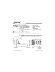
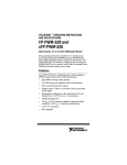
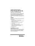
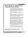
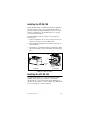
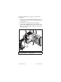
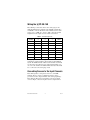
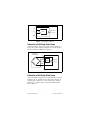
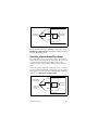
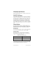
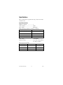
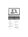
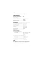
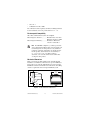
FieldPoint Operating Instructions
FP-SG-140 AND CFP-SG-140
Eight-Channel Strain-Gauge Input Modules
These operating instructions describe how to install and use the
FP-SG-140 and cFP-SG-140 strain-gauge input modules (referred
to inclusively as the [c]FP-SG-140). For information about
configuring and accessing the [c]FP-SG-140 over a network, refer
to the user manual for the FieldPoint network module you are
using.
Features
The [c]FP-SG-140 is a FieldPoint strain-gauge input module with
the following features:
•
Internal support for full- and half-bridge configurations with
programmable bridge completion
•
Programmable excitation for each channel: 2.5, 5, or 10 V
•
Four input ranges: ±3.5, ±7.5, ±30, and ±60 mV/V with
overranging
•
Three filter settings: 15, 60, and 240 Hz
•
16-bit resolution
•
2,300 Vrms transient overvoltage protection between the
inter-module communication bus and the I/O channels
•
–40 to 70 °C operation
•
Hot plug-and-play
FieldPoint™, National Instruments™, NI™, and ni.com™ are trademarks of National Instruments Corporation.
Product and company names mentioned herein are trademarks or trade names of their respective companies.
For patents covering National Instruments products, refer to the appropriate location: Help»Patents in your software,
the patents.txt file on your CD, or ni.com/patents.
323346A-01
October 2002
© 2002 National Instruments Corp. All rights reserved.
Installing the FP-SG-140
The FP-SG-140 mounts on a FieldPoint terminal base (FP-TB-x).
Hot plug-and-play enables you to install the FP-SG-140 onto a
powered terminal base without disturbing the operation of other
modules or terminal bases. The FP-SG-140 receives operating
power from the terminal base.
To install the FP-SG-140, refer to Figure 1 and complete the
following steps:
1. Slide the terminal base key to either position X, used for any
module, or position 1, used for the FP-SG-140.
2. Align the FP-SG-140 alignment slots with the guide rails on
the terminal base.
3. Press firmly to seat the FP-SG-140 on the terminal base. When
the module is firmly seated, the terminal base latch locks it into
place.
Key
Latch
Alignment
Slot
Guide Rails
I/O Module
Terminal Base
Figure 1. Installing the Module
Installing the cFP-SG-140
The cFP-SG-140 mounts on a Compact FieldPoint backplane
(cFP-BP-x). Hot plug-and-play enables you to install the
cFP-SG-140 onto a powered backplane without disturbing the
operation of other modules or connector blocks. The cFP-SG-140
receives operating power from the backplane.
FP-SG-140 and cFP-SG-140
2
ni.com
To install the cFP-SG-140, refer to Figure 2 and complete the
following steps:
1. Align the captive screws on the cFP-SG-140 with the holes on
the backplane. The alignment keys on the cFP-SG-140 prevent
backward insertion.
2. Press firmly to seat the cFP-SG-140 on the backplane.
3. Using a number 2 Phillips screwdriver with a shank of at least
64 mm (2.5 in.) length, tighten the captive screws to 1.1 N ⋅ m
(10 lb ⋅ in.) of torque. The nylon coating on the screws prevents
them from loosening.
5
2
1
4
5
4
3
1 cFP Backplane
2 cFP Controller Module
3 cFP-SG-140
4 Captive Screws
5 Screw Holes
Figure 2. Installing the cFP-SG-140
© National Instruments Corp.
3
FP-SG-140 and cFP-SG-140
Wiring the [c]FP-SG-140
The following sections show how to wire strain gauges to the
[c]FP-SG-140 using the terminals on the FP-TB-x terminal base
or cFP-CB-x connector block. The four terminals used for strain
gauges are Vexc, COM, Vin+, and Vin–. Table 1 lists the terminal
assignments for the signals associated with each channel.
Table 1. Terminal Assignments
Channel
Vin+
Vin–
Vexc
COM
0
1
2
17
18
1
3
4
19
20
2
5
6
21
22
3
7
8
23
24
4
9
10
25
26
5
11
12
27
28
6
13
14
29
30
7
15
16
31
32
The eight input channels of the [c]FP-SG-140 share a common
ground that is isolated from the other modules of the FieldPoint
system. The COM terminals of all the channels and the C terminals
are all connected together. If you are using shielded wiring, you
can connect the shield to the COM terminal, but only if the shield
is not connected to the strain-gauge circuit.
Connecting Sensors to the Input Channels
Each channel pulses a voltage between the Vexc and COM
terminals. The Vin+ and Vin– terminals measure the voltage
generated across the output terminals of the strain-gauge bridge.
Each channel is filtered, then sampled by an analog-to-digital
converter. Figure 3 shows the input circuit for a single channel.
FP-SG-140 and cFP-SG-140
4
ni.com
Vexc
Vin+
16-Bit
ADC
Vin–
+
–
Excitation
Voltage
COM
[c]FP-SG-140
Figure 3. [c]FP-SG-140 Input Circuit
Connecting a Full-Bridge Strain Gauge
Connect the positive output to Vin+ and the negative output to Vin–.
Connect the positive excitation terminal to Vexc and the negative
excitation terminal to COM. Refer to Figure 4.
Full-Bridge
Strain Gauge
Vexc
Vin+
Input
Circuitry
Vin–
+
–
Excitation
Voltage
COM
[c]FP-SG-140
Figure 4. Connecting a Full-Bridge Strain Gauge to One Channel
Connecting a Half-Bridge Strain Gauge
Connect the positive output to the Vin+ terminal and do not connect
anything to the Vin– terminal. Connect the positive output to Vin+
and the negative output to Vin–. Connect the positive excitation
terminal to Vexc and the negative excitation terminal to COM.
Refer to Figure 4.
© National Instruments Corp.
5
FP-SG-140 and cFP-SG-140
Vexc
Vin+
Half-Bridge
Strain Gauges
Vin–
Input
Circuitry
+
–
Excitation
Voltage
COM
[c]FP-SG-140
Figure 5. Connecting a Half-Bridge Strain Gauge to One Channel
For any channel connected to a half-bridge strain gauge, select
Half-Bridge Completion ON in the Channel Configuration dialog
box in the FieldPoint software.
Connecting a Quarter-Bridge Strain Gauge
For quarter-bridge sensors, you need an external resistor with the
same resistance as the quarter-bridge strain gauge. The accuracy of
your measurements depends on matching the value of this
completion resistor to the nominal resistance value of the strain
gauge.
Connect the positive output of the strain gauge to Vin+, connect the
positive excitation terminal of the strain gauge to Vexc, and connect
the completion resistor between Vin+ and COM. In the FieldPoint
software, select Half-Bridge Completion ON.
Vexc
Quarter-Bridge
Strain Gauges
External
Completion
Resistor
Vin+
Vin–
Input
Circuitry
+
–
Excitation
Voltage
COM
[c]FP-SG-140
Figure 6. Connecting a Quarter-Bridge Strain Gauge to One Channel
FP-SG-140 and cFP-SG-140
6
ni.com
Configuring Input Channels
After you connect the strain gauges, configure the input channels
in the FieldPoint software.
Selecting an Input Range
To prevent inaccurate readings, choose an input range such that the
signal you are measuring does not exceed either end of the range.
Overranging allows the [c]FP-SG-140 to measure a little beyond
the nominal value of each input range. For example, the actual
measurement limit of the ±3.5 mV/V range is ±3.90625 mV/V.
Overranging enables the [c]FP-SG-140 to compensate for field
devices with span errors of up to 12%. Also, with the overranging
feature, a noisy signal near full scale does not create rectification
errors.
Channel Attributes
The Channel Attributes panel has an Attribute pulldown menu
from which you choose the attribute you want to configure: Noise
Rejection, Excitation Voltage, or Half-Bridge Completion.
Noise Rejection
Each analog input channel has a software-enabled comb filter that
you can set to reject frequencies above 15, 60, or 240 Hz.
Excitation Voltage
You can choose 2.5, 5, or 10 V excitation for each channel.
The current limit is 21 mA. Table 2 shows the minimum bridge
resistance at each excitation voltage level.
Table 2. Minimum Bridge Resistance
Excitation Voltage
Minimum Bridge Resistance
2.5 V
120 Ω
5V
240 Ω
10 V
477 Ω
If the bridge resistance is lower than the minimum value for the
excitation voltage level, the readings are not valid and the red LED
for the channel lights, indicating an overcurrent error.
© National Instruments Corp.
7
FP-SG-140 and cFP-SG-140
Half-Bridge Completion
You can enable or disable half-bridge completion for each channel.
Enable half-bridge completion for half-bridge and quarter-bridge
sensors. When a channel is configured with the Half-Bridge
Completion ON attribute value, the Vin– input is internally
disconnected from the screw terminal and connected to a
completion circuit.
Using Measured Values
The [c]FP-SG-140 reports measurements in units of mV/V
(millivolts per volt of excitation), allowing the [c]FP-SG-140 to
take measurements from a wide variety of transducers, such as load
cells and pressure sensors. To convert measurements from mV/V to
the physical units of a particular transducer, multiply by a constant
as shown in the following sections.
Converting to Microstrain
Strain is measured in units of microstrain (µε). The constant you
use to convert readings from mV/V to µε depends on whether you
are using a full-, half-, or quarter-bridge strain-gauge circuit.
If you are using a full-bridge circuit similar to the one in Figure 4,
you can convert readings from mV/V to µε by multiplying the
readings by the following constant:
–1
constant = 1000 × -------GF
where GF is the gauge factor of the strain gauges. The gauge factor
is listed in the strain gauge data sheet.
For example, assume a full-bridge circuit has strain gauges with a
gauge factor of 2.03. Using the previous constant equation, the
constant is –492.6108, as shown in the following calculation:
–1
1000 × --------------- = – 492.6108
( 2.03 )
If the [c]FP-SG-140 reads 0.75 mV/V, the strain in units of
microstrain is –369.5 µε, as shown in the following calculations:
reading in mV/V × constant = reading in microstrain
(0.75) × (–492.6108) = –369.5 µε
FP-SG-140 and cFP-SG-140
8
ni.com
If you are using a half-bridge circuit similar to the one in Figure 5,
you can convert readings from mV/V to µε by multiplying the
readings by the following constant:
–2
constant = 1000 × -------GF
If you are using a quarter-bridge circuit similar to the one in
Figure 6, you can convert readings from mV/V to µε by
multiplying the readings by the following constant:
–4
constant = 1000 × -------GF
For more information about strain gauges and how the equations in
this section are derived, refer to NI Application Note 078, Strain
Gauge Measurement – A Tutorial, available at ni.com.
Converting to Other Physical Units
If you use the [c]FP-SG-140 to measure the output of other
transducers, such as load cells or pressure transducers, you can
convert measurements from mV/V to other physical units such as
force or pressure.
Load cells are specified by maximum voltage output at maximum
load capacity. To convert load cell readings from the [c]FP-SG-140
to units of force or pressure, multiply the readings by the following
constant:
constant = FullScaleCapacity
-------------------------------------------------FullScaleOutput
where FullScaleOutput is the maximum voltage output of the load
cell in mV/V, and FullScaleCapacity is the maximum capacity of
the load cell in units of force or pressure.
For example, if you are using a load cell with a maximum capacity
of 1,000 lb and a maximum output of 2 mV/V, the constant is 500,
as shown in the following calculation:
1000
------------ = 500
2
This means the transducer outputs 1 mV/V per 500 lb of force
applied to it. To convert readings to lb, multiply the output of the
[c]FP-SG-140 by 500. If the [c]FP-SG-140 has a reading of
© National Instruments Corp.
9
FP-SG-140 and cFP-SG-140
0.75 mV/V, the force in pounds that is applied to the load cell is
375 lb, as shown in the following calculation:
0.75 × 500 = 375 lb
Status Indicators
Figure 7 shows the [c]FP-SG-140 status indicators.
Figure 7. Status Indicators
The [c]FP-SG-140 has two green status LEDs, POWER and
READY. After you insert the [c]FP-SG-140 into a terminal base or
backplane and apply power to the connected network module, the
green POWER indicator lights and the [c]FP-SG-140 informs the
network module of its presence. When the network module
recognizes the [c]FP-SG-140, it sends initial configuration
information to the [c]FP-SG-140. After receiving this initial
information, the green READY indicator lights and the
[c]FP-SG-140 is in normal operating mode.
In addition to the green POWER and READY indicators, each
channel has a numbered, red LED that indicates overcurrent
conditions. When a transducer draws more than 21 mA from the
excitation terminal, the red LED for that channel lights and an
overcurrent error is reported to the network module. This also
occurs if the Vexc output is shorted to ground.
Upgrading the FieldPoint Firmware
You may need to upgrade the FieldPoint firmware when you add
new I/O modules to the FieldPoint system. For information on
determining which firmware you need and how to upgrade, go to
ni.com/info and enter fpmatrix.
Isolation and Safety Guidelines
Read the following information before
attempting to connect the [c]FP-SG-140 to any circuits
that may contain hazardous voltages.
Caution
FP-SG-140 and cFP-SG-140
10
ni.com
This section describes the isolation of the [c]FP-SG-140 and its
compliance with international safety standards. The field wiring
connections are isolated from the backplane and the inter-module
communication bus. The isolation is provided by the module,
which has optical and galvanic isolation barriers designed and
tested to protect against transient fault voltages of up to 2,300 Vrms.
Follow these guidelines to ensure a safe total system:
•
The [c]FP-SG-140 has a safety isolation barrier between the
I/O channels and the inter-module communication bus. There
is no isolation between channels unless otherwise noted. If any
of the channels on a module are wired at a hazardous potential,
make sure that all other devices or circuits connected to that
module are properly insulated from human contact.
•
Do not share the external supply voltages (the V and C
terminals) with other devices (including other FieldPoint
devices), unless those devices are isolated from human contact.
•
For Compact FieldPoint, you must connect the protective earth
(PE) ground terminal on the cFP-BP-x backplane to the system
safety ground. The backplane PE ground terminal has the
following symbol stamped beside it: . Connect the
backplane PE ground terminal to the system safety ground
using 14 AWG (1.6 mm) wire with a ring lug. Use the 5/16 in.
panhead screw shipped with the backplane to secure the ring
lug to the backplane PE ground terminal.
•
As with any hazardous voltage wiring, make sure that all
wiring and connections meet applicable electrical codes and
commonsense practices. Mount terminal bases and backplanes
in an area, position, or cabinet that prevents accidental or
unauthorized access to wiring that carries hazardous voltages.
•
Operate the [c]FP-SG-140 only at or below Pollution
Degree 2. Pollution Degree 2 means that only nonconductive
pollution occurs in most cases. Occasionally, however, a
temporary conductivity caused by condensation must be
expected.
•
Refer to the FieldPoint product label for regulatory
certification under hazardous location standards. If the
FieldPoint product is not certified for operation in hazardous
locations, do not operate it in an explosive atmosphere or
where there may be flammable gases or fumes.
© National Instruments Corp.
11
FP-SG-140 and cFP-SG-140
Specifications
These specifications are typical for the range –40 to 70 °C unless
otherwise noted.
Input Characteristics
Number of channels.......................... 8
ADC resolution................................. 16 bits
Type of ADC..................................... Delta-sigma
Input signal ranges (software-selectable per channel)
Nominal
With Overranging
±3.5 mV/V
±3.90625 mV/V
±7.5 mV/V
±7.8125 mV/V
±30 mV/V
±31.25 mV/V
±60 mV/V
±62.5 mV/V
Filter settings .................................... 15, 60, 240 Hz
Excitation voltage ............................. 2.5, 5, 10 V, current is limited
to 21 mA per channel
Pulse frequency and width
Filter Setting (Hz)
Pulse Width (ms)
Pulse Frequency (s)
15
324
1.15
60
116
0.95
240
70
0.90
FP-SG-140 and cFP-SG-140
12
ni.com
Figure 8 shows how the pulse frequency and width are defined.
1
2
1 Pulse Frequency
2 Pulse Width
Figure 8. Pulse Width and Pulse Frequency
All-channel update rate
Filter Setting (Hz)
Update Rate (s)
15
1.15
60
0.95
240
0.90
Input impedance................................ 20 MΩ
Offset error
15 to 35 °C ................................. 7.6 µV typ, 28 µV max
–40 to 70 °C ............................... 50 µV typ, 140 µV max
Gain error
15 to 35 °C ................................. 0.06% of full scale (fs)
–40 to 70 °C ............................... 0.4% fs
Input noise (60 Hz filter)
±3.5 mV/V.................................. ±3 LSB peak-to-peak
±7.5 mV/V.................................. ±2 LSB peak-to-peak
Other ranges ............................... ±1 LSB peak-to-peak
Physical Characteristics
Indicators .......................................... Green POWER and
READY indicators; eight
red overcurrent indicators
© National Instruments Corp.
13
FP-SG-140 and cFP-SG-140
Weight
FP-SG-140.................................. 140 g (4.8 oz)
cFP-SG-140................................ 110 g (3.7 oz)
Power Requirements
Power from network module ............ 1 W
Isolation Voltage
Channel-to-channel isolation ............ No isolation between
channels
Transient overvoltage........................ 2,300 Vrms
Environmental
FieldPoint modules are intended for indoor use only. For outdoor
use, they must be mounted inside a sealed enclosure.
Operating temperature ...................... –40 to 70 °C
Storage temperature .......................... –55 to 85 °C
Humidity ........................................... 10 to 90% RH,
noncondensing
Maximum altitude............................. 2,000 m
Pollution Degree .............................. 2
Shock and Vibration
Operating shock (IEC 68-2-27)
cFP-SG-140..................................50 g, 3 ms half sine, 3 shocks;
30 g, 11 ms half sine,
3 shocks
Operating vibration, random (IEC 60068-2-34)
FP-SG-140.................................. 10–500 Hz, 2.2 grms
cFP-SG-140................................ 10–500 Hz, 5 grms
Operating vibration, sinusoidal (IEC 60068-2-6)
[c]FP-SG-140 ............................. 10–500 Hz, 5 g
Safety
The [c]FP-SG-140 is designed to meet the requirements of the
following standards for safety and electrical equipment for
measurement, control, and laboratory use.
•
EN 61010-1, IEC 61010-1
FP-SG-140 and cFP-SG-140
14
ni.com
•
UL 3121-1
•
CAN/CSA C22.2 No. 1010.1
For certifications under regulatory standards, including hazardous
location standards, refer to the product label or to ni.com.
Electromagnetic Compatibility
CE, C-Tick, and FCC Part 15 (Class A) Compliant
Electromagnetic emissions ............... EN 55011 Class A at 10 m
FCC Part 15A above 1 GHz
Electromagnetic immunity................ Evaluated to EN 61326:
1997/A1: 1998, Table 1
For full EMC compliance, you must operate this
device with shielded cabling. Refer to the Declaration of
Conformity (DoC) for this product for any additional
regulatory compliance information. To obtain the DoC
for this product, click Declaration of Conformity at
ni.com/hardref.nsf/. For FCC regulatory
statements, refer to the Read Me First document that
accompanies this product.
Note
Mechanical Dimensions
Figure 9 shows the mechanical dimensions of the FP-SG-140
installed on a terminal base. Dimensions are given in millimeters
[inches]. If you are using the cFP-SG-140, refer to the Compact
FieldPoint controller user manual for the dimensions and cabling
clearance requirements of the Compact FieldPoint system.
107.19
[4.22]
109.5
[4.31]
91.44
[3.60]
Figure 9. FP-SG-140 Mechanical Dimensions
© National Instruments Corp.
15
FP-SG-140 and cFP-SG-140
Where to Go for Support
For more information about setting up the FieldPoint system, refer
to these National Instruments documents:
•
FieldPoint network module user manual
•
Other FieldPoint I/O module operating instructions
•
FieldPoint terminal base operating instructions
Go to ni.com/support for the most current manuals, examples,
and troubleshooting information.
For telephone support in the United States, create your service
request at ni.com/ask and follow the calling instructions or dial
512 795 8248. For telephone support outside the United States,
contact your local branch office:
Australia 03 9879 5166, Austria 0662 45 79 90 0,
Belgium 02 757 00 20, Brazil 55 11 3262 3599,
Canada (Calgary) 403 274 9391,
Canada (Montreal) 514 288 5722,
Canada (Ottawa) 613 233 5949, Canada (Québec) 514 694 8521,
Canada (Toronto) 905 785 0085, China 86 21 6555 7838,
Czech Republic 02 2423 5774, Denmark 45 76 26 00,
Finland 09 725 725 11, France 01 48 14 24 24,
Germany 089 741 31 30, Greece 01 42 96 427,
Hong Kong 2645 3186, India 91 80 4190000,
Israel 03 6393737, Italy 02 413091, Japan 03 5472 2970,
Korea 02 3451 3400, Malaysia 603 9596711,
Mexico 001 800 010 0793, Netherlands 0348 433466,
New Zealand 09 914 0488, Norway 32 27 73 00,
Poland 22 3390 150, Portugal 210 311 210, Russia 095 238 7139,
Singapore 65 6 226 5886, Slovenia 3 425 4200, South
Africa 11 805 8197, Spain 91 640 0085, Sweden 08 587 895 00,
Switzerland 056 200 51 51, Taiwan 02 2528 7227,
United Kingdom 01635 523545
*323346A-01*
323346A-01
Oct02

![[c]FP-DO-401 Operating Instructions](http://vs1.manualzilla.com/store/data/005693758_1-4b10a2df6965457ee651014d1377996a-150x150.png)