1
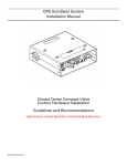
Reactive Steering Kit
Installation Manual
PN: 602-0275-01-A
LEGAL DISCLAIMER
Note: Read and follow ALL instructions in this manual carefully before installing or operating the AutoSteer system.
Note: Take careful note of the safety information in the Safety Information section and throughout this manual.
The manufacturer disclaims any liability for damage or injury that results from failure to follow the instructions and warnings
set forth herein.
Please take special note of the following warnings:
1. There is NO obstacle avoidance system included in the manufacturer’s product. Therefore, users must always have an
operator on the equipment when the AutoSteer system is in use to look for any obstacles including people, animals, trees,
ditches, buildings, etc.
2. During installation of the AutoSteer system and during the Calibration and Tuning processes the vehicle's wheels turn from
side to side and the vehicle moves. Be sure that all people and obstacles are clear of the vehicle before installation, calibration and tuning, or use of the AutoSteer system.
3. Use of the AutoSteer system is NOT permitted while the vehicle is on public roads or in public areas. Ensure that the system is OFF before driving on roads or in public areas.
ii
AutoSteer System
Special Requirements
Tools
This list consists of the tools required to complete the installation. The installer is assumed to have a complete set of common
installation tools.
11/16” open wrench
Cleaning brush
3/4” open wrench
Cleaning rags
13/16” open wrench
Oil catch pan
7/8” open wrench
1” open wrench
Hardware Installation Manual
iii
Safety Information
Warning Alerts
The AutoSteer system installer and manufacturer disclaim any responsibility for damage or physical harm caused by failure to
adhere to the following safety requirements:
•
•
As the operator of the vehicle, you are responsible for its safe operation.
The AutoSteer system is not designed to replace the vehicle’s operator.
Note: Verify all screws, bolts, nuts, and cable connections are tight after the final installation of the AutoSteer system on
the vehicle.
WARNING
To avoid electrical shock hazards, remove the Roof Module
from the vehicle before driving under low structures or low
electrical power lines.
WARNING
To prevent injury from falling, ensure you are in a stable
position on the vehicle when installing or removing the Roof
Rail and Roof Module. If the vehicle does not provide a safe
platform, use a ladder to safely access the vehicle roof while
installing or removing the Roof Rail and Roof Module.
WARNING
To prevent accidental death or injury from being run over by
the vehicle, never leave the vehicle's operator chair with the
AutoSteer system engaged.
iv
AutoSteer System
WARNING
High-Pressure Fluid Hazard
Read this manual before installation. Wear hand and eye
protection while performing hydraulic system maintenance.
Relieve hydraulic system pressure before servicing the
hydraulic system.
WARNING
To understand the potential hazards associated with the
operation of AutoSteer system equipment read the provided
documentation before installing the AutoSteer system on a
vehicle.
WARNING
To prevent the accidental engagement of AutoSteer and loss
of vehicle control while driving on roads, shut down the
AutoSteer system (exit the program). Never drive on roads
or in public areas with the AutoSteer system turned on.
WARNING
Do not stand close to the wheels and do not move the
machine while you are servicing the steering system or
AutoSteer system. Turn off the engine and engage the
parking brake before standing under or next to the machine.
Hardware Installation Manual
v
Caution Alerts
The AutoSteer system installer and manufacturer disclaim any responsibility for damage or physical harm caused by failure to
adhere to the following safety requirements:
CAUTION
The Roof Module must be removed when transporting or
driving the vehicle at speeds above 30 mph (50 km/h). The
Roof Module can possibly detach due to wind loads at
higher speeds.
CAUTION
The AutoSteer system does not detect obstacles in the
vehicle’s path. The operator must observe the path being
driven in order to avoid obstacles.
CAUTION
When engaged, the AutoSteer system controls only the
steering of the vehicle. The operator must control the speed
of the vehicle.
CAUTION
The AutoSteer system must be powered OFF when
installing or removing the Roof Module.
vi
AutoSteer System
CAUTION
The Roof Module must always be firmly secured to the Roof
Rail using the hardware whenever the vehicle is in operation
to prevent the Roof Module from releasing from its bracket
and falling.
Vehicle Requirements
The vehicle steering system must be in good working order before installing the AutoSteer system. Check for loose or worn
parts. Before installing the AutoSteer system drive the vehicle and confirm that it steers straight and the wheels can be turned
from lock to lock. Check the steering system hydraulic hoses and connections to ensure there are no oil leaks.
The vehicle electrical system and battery must be in good working order.
The vehicle should be fully cleaned before installing the AutoSteer system. A clean vehicle will improve the overall
installation and cable routing.
Hardware Installation Manual
vii
Important Information
Note: Verify all screws, bolts, nuts, hose connections, and cable connections are tight after the final installation of the
AutoSteer system on the vehicle.
Technical Support
Refer to your Display user manual for technical support information.
Contact Information
Refer to your Display user manual for contact information.
Copyright © 2010 All Rights Reserved.
viii
AutoSteer System
Table of Contents
Chapter 1
Overview ....................................................................................................... 1
Introduction . . . . . . . . . . . . . . . . . . . . . . . . . . . . . . . . . . . . . . . . . . . . . . . . . . . . . . . . . . . . . . . . 2
Theory of Operation. . . . . . . . . . . . . . . . . . . . . . . . . . . . . . . . . . . . . . . . . . . . . . . . . . . . . . . . . . 2
Kit Components . . . . . . . . . . . . . . . . . . . . . . . . . . . . . . . . . . . . . . . . . . . . . . . . . . . . . . . . . . . . 3
Cable Diagram . . . . . . . . . . . . . . . . . . . . . . . . . . . . . . . . . . . . . . . . . . . . . . . . . . . . . . . . . . . . . 4
Hose Diagram . . . . . . . . . . . . . . . . . . . . . . . . . . . . . . . . . . . . . . . . . . . . . . . . . . . . . . . . . . . . . . 5
Chapter 2
Installation Procedure ...................................................................................... 7
Chapter 3
Troubleshooting............................................................................................ 11
Hardware Installation Manual
ix
x
AutoSteer System
1
Overview
The information in this chapter is divided into the following sections.
•
•
•
•
•
Introduction
Theory of Operation
Kit Components
Cable Diagram
Hose Diagram
Hardware Installation Manual
1
Introduction
Introduction
The reactive steering kit is used for installing the AutoSteer valve PN 200-0457-01 on vehicles that have a reactive steering
Orbitrol to prevent the rotation of the steering wheel when AutoSteer is engaged. Reactive steering systems on farm vehicles
use an Orbitrol that allows the centering of the front wheels when the steering wheel is released, much like a passenger car. To
determine if a farm vehicle has reactive steering, steer the vehicle in a small circle at low speed and let go of the steering
wheel. If the steering wheel rotates slowly and the front wheels return to center position (straight ahead), it is a reactive
steering system. If it is a non-reactive steering system, the steering wheel will not rotate and the front wheels will hold their
position. Reactive steering systems are not very common in North America and are more often found on tractors manufactured
in Europe.
Note: The installation of the two solenoids provided in the reactive steering kit will require hose adapters and custom
hoses that match the type of hose fitting used on the vehicle.
Note: Installing the AutoSteer valve PN 200-0457-01 on reactive steering vehicles without installing the solenoid valves
will result in sluggish AutoSteering. Also, the steering wheel will rotate slowly right and left while in AutoSteer mode.
Manual steering is not affected if you do not install the solenoid valves on a reactive steering vehicle.
Note: Do not install the reactive steering solenoid valves with AutoSteer valves that are not covered in this manual.
Theory of Operation
The reactive steering kit provides two 12V normally-open solenoid valves that are installed on the right and left steering lines
close to the Orbitrol along with the AutoSteer valve. The solenoids are normally open (NO) and allow normal steering oil flow
between the Orbitrol and the steering cylinder when AutoSteer is disengaged. When AutoSteer is engaged, the two solenoid
valves close and block oil flow across the Orbitrol, thus preventing the rotation of the steering wheel while AutoSteering. In
AutoSteer mode, the steering wheel will feel locked and will not rotate until AutoSteer is disengaged.
Note: The solenoid valves are rated for a maximum oil flow of 6 GPM (27 L/min.) and a maximum operating pressure of
3000psi (210 bar). The two threaded ports are size SAE -6 ORB (9/16-18).
2
AutoSteer System
Kit Components
Kit Components
The parts in this kit are shown in Figure 1-1 and its components are defined in Table 1-1.
Figure 1-1
Reactive Steering Kit (PN: 200-0562-01)
Table 1-1
Installation Kit Components (PN: 200-0562-01)
Item
Component
Part Number
Quantity
1.
12V Solenoid Assembly
500-0361-01
2
2.
Installation Manual
602-0275-01
1
3.
Cable Harness
201-0480-01
1
Hardware Installation Manual
3
Cable Diagram
Cable Diagram
4
AutoSteer System
Hose Diagram
Hose Diagram
Hardware Installation Manual
5
Hose Diagram
6
AutoSteer System
2
Installation Procedure
To install the solenoid valves:
1. Follow the instructions provided with your AutoSteer kit or AutoSteer valve to install the AutoSteer valve and the oil
supply hoses (Pressure, Tank, LS).
2. Follow all safety instructions in this manual as well as those provided with your AutoSteer kit.
3. Before installing the right and left AutoSteer hoses, refer to the Hose Diagram on page 5 for the correct position of the
reactive steering solenoid valves in the vehicle steering circuit.
4. Check if the cartridges on the two solenoid valves are fully threaded and tight.
5. Check if the solenoid coils are tight and secured by the hex nut. Do not over-tighten the hex nut (4-6 ft.-lbs Max, 5-8 Nm
Max). For an example of a fully assembled Solenoid valve, see Figure 2-1.
Note: The exact configuration of the hose adapters used to install the solenoid valves will depend on the vehicle and
the space available for installing the two solenoids. The hose adapters must match the type of hose fittings used on the
vehicle (JIC, ORFS, Metric etc.). Female thread adapters may allow the installation of the solenoids directly on the
Orbitrol right and left steer port. Some vehicles with limited space around the Orbitrol may require jumper hoses to
install the solenoids away from the Orbitrol.
Note: The solenoid valve has two ports and either port can be used as an IN or OUT port. This means that you can
rotate the solenoid valve as necessary to best fit your vehicle without worrying about which port faces the Orbitrol and
which port faces the steering cylinder.
Figure 2-1
Fully Assembled Solenoid
Hardware Installation Manual
7
Installation Procedure
6. Install the solenoid valves on the right and left steer lines that exit the Orbitrol. See Figure 2-2 and Figure 2-3. The
solenoids are installed between the AutoSteer Tee connections and the Orbitrol on the right and left steer lines.
Note: You may install the solenoids directly on the right and left Orbitrol ports if you have the necessary threaded
adapters.
8
Figure 2-2
Solenoid Installed on the Orbitrol Left Steer Port
Figure 2-3
Both Solenoids Installed on the Orbitrol Left and Right Steer Ports
AutoSteer System
Installation Procedure
•
Alternatively you may install the solenoids adjacent to the AutoSteer Tee adapters further away from the Orbitrol in a
protected position. See Figure 2-4. Hose adapters and fittings will be required to complete the installation.
Figure 2-4
Solenoid Installed on a Steering Line
7. Complete the hydraulic installation for Pressure, Tank and Load Sense per the Hardware Installation Manual provided with
your AutoSteer kit so that it matches the vehicle. The type of installation varies depending on the type of hydraulic system
found on the vehicle (open center, closed center, power beyond etc.…).
8. Connect reactive steering Cable Harness PN 201-0480-01 to the two solenoid valves, the Pressure Transducer on the
AutoSteer valve and the 10-pin connector on the SA Module Cable Harness. See Cable Diagram on page 4. You will not
use the small transducer harness provided with your AutoSteer valve.
9. Rout all cables in protected positions and secure with cable ties.
10. Ensure that all hoses and connections are tight. Keep all hoses and cables away from hot parts such as exhaust manifolds
and moving parts, and ensure that all cables are connected at both ends and secured in a protected position with cable ties.
11. Run the vehicle engine for a few seconds, turn the engine OFF, and check for oil leaks.
12. Ensure that manual steering is normal after the installation is completed.
•
•
The steering wheel should steer the vehicle normally when AutoSteer is disengaged.
In AutoSteer mode the steering wheel will remain locked and will not steer the vehicle.
13. Check if AutoSteer is normal in AutoSteer mode.
•
•
The steering wheel should not rotate while in AutoSteer mode.
The wheels should turn right and left when AutoSteer is engaged and a steering command is sent to the valve. This can be
checked using commands on the User Terminal. See your User Manual for further information.
14. Confirm the operation of AutoSteer kick-out when the driver turns the steering wheel while in AutoSteer mode.
Hardware Installation Manual
9
Installation Procedure
10
AutoSteer System
3
Troubleshooting
Issue: Steering wheel is locked when in manual steer mode.
Solution: Wrong hose connections or wrong type of solenoid valve. The solenoid valve should be Normally Open, in other
words, it should be OPEN when not energized and CLOSED when energized with 12 volts. You can check the correct
operation of the solenoid valve by blowing (compressed) air through it.
Issue: Steering wheel is turning while in AutoSteer mode.
Solution: This means the solenoid is either not installed in the correct location in the steering circuit or the cable harness is not
connected to the solenoids. Check the cable harness and position of the solenoid in the steering circuit.
Issue: AutoSteer valve does not steer the vehicle.
Solution: Check if the solenoid valve is installed in the correct position in the steering circuit.
Issue: Manual kick-out behavior is different if you turn the steering wheel left or right.
Solution: This will occur if only one of the two solenoids is closing when AutoSteer is engaged. Check cables, connectors and
solenoid coils. Normal coil resistance should be 6 Ohms.
Issue: Coils are hot when AutoSteer is engaged.
Solution: It is normal for the coils to feel warm or hot after AutoSteer has been engaged for a long time. Heating is caused by
the electrical current and also the hot oil flowing through the steering circuit. To avoid excessive heating, do not cover the coils
and keep them clean and free of a buildup of mud or other debris.
Issue: Manual steering feels hard when turning the steering wheel quickly.
Solution: This may happen in very cold weather until the oil warms up. This may also happen on very large vehicles that
require a very high oil flow for manual steering. Contact your AutoSteer dealer if the problem persists.
Hardware Installation Manual
11
Troubleshooting
12
AutoSteer System