1
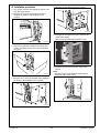
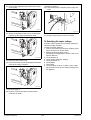
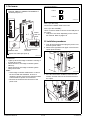
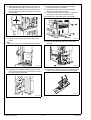
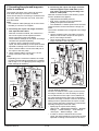
11. Using the two screws, secure the relay circuit
board.
Note:
Be sure to use the two screws removed in step 7.
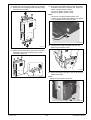
8. Attach the two supplied shoulder screws for
mounting the relay circuit board to the main circuit board.
A0YEIXC015DB
A0YEIXC017DA
9. Flip the switches 1 and 2 up as shown in the illustration.
Note:
If the switches are not flipped up, this option cannot be detected properly.
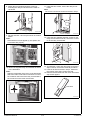
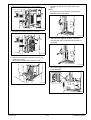
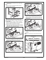
12. Using the two supplied shoulder screws for the
relay circuit board connector, secure the connector of the relay circuit board.
A0YEIXC018DA
A0YEIXC059DA
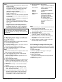
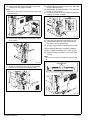
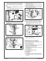
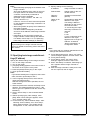
13. To install the covers and other parts removed in
steps 4 and 5, reverse the removal procedure.
14. If the fax kit was removed in step 3, install it at
the location from where it was removed.
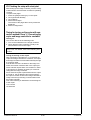
15. Remove the knockout from the cover removed in
step 2 with nippers.
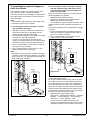
10. Mount the supplied relay circuit board as shown
in the illustration.
Note:
Align the matchmark of the relay circuit board with
that of the main circuit board. Connect the connector located on the back of the relay circuit board to
the connector on the main circuit board.
Knockout
A0YEIXC061DA
A0YEIXC060DA
Installation Manual
E-4
Y110511-5