1
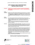
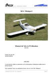
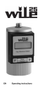
SD- 1 Minisport
s.r.o.
PAGE:1
B&S engine installation manual
CZECH REPUBLIC
CONTETS OF KIT
1. Manual and drawing
2. Engine
3. Propeller bolts+washers
4. Propeller spinner+ HW
5. Propeller
6. Engine mount
6. Exhaust muffler + hoses
8. Upper+lower cowling+installation HW
FOREWORD
Study completely this manual and installation drawing before start of work.
ELECTRICAL INSTALLATION
Usual electrical installation on SD-1 contains engine starter, 5W COM transceiver and 1A 12V outlet
for juicing of GPS. The 6 Ah battery is sufficient for this task. We recommend use of battery with
higher starting current allowed (min 100 A).
Typical electrical installation
INSTALLATION PROCEDURE (DWG SD1- 94- 000)
1. Firewall preparation
Drill holes for engine mount, rescue system holders, rudder cable bolts (only if adjustable
pedals are installed), fuel fitting, throttle and choke control bowdens, electrical installation
grommets and battery holder into firewall in accordance to dwg
2. Installation of fuel tank vent
2.1
2.2
2.3
2.4
Turn fuselage upside down and rest it on support in the place of cockpit so that space
under fuel tank is unobstructed and you can get inside with upper part of your body.
Drill hole for vent tube into fuselage bottom in accordance to drawing.
Install outlet vent tube in accordance to drawing using sheet clamps
Connect vent tube of tank with outlet tube using clear hose
3. Installation of cockpit fuel line (fuselage upside down)
3.1
Screw the fuel valve assembly into the tank outlet thread for check. Check position of
valve lever against instrument panel and mark it on assembly. Screw assembly out.
3.2
Assemble elbow, fuel valve and AN822 fitting in accordance to previous setting.
Use Loctite or similar screw glue. Minimum torque moment is 10 Nm.
Use gripper for easier work.
3.3.
Install assembly on the fuel tank. Use Loctite again. The AN822 outlet should point
perpendicularly on the firewall
3.4.
Install elbow AN838 on the firewall
3.5.
Install delivered fuel line assembly. Use Loctite on nuts.
SD- 1 Minisport
s.r.o.
CZECH REPUBLIC
B&S engine installation manual
PAGE:2
SD- 1 Minisport
s.r.o.
PAGE:3
B&S engine installation manual
CZECH REPUBLIC
4. Installation of equipment on the firewall (fuselage upside down)
4.1
Install expansion tank, engine electronics, battery and oil cooler while is fuselage upside
down.
4.2
Install bolts of rudder cables if are adjustable pedals installed on the plane.
5. Preliminary installation of mount and engine for setting of cowling position
5.1
Check possible collision of engine mount pads with nuts of rudder cable bolts (only if
adjaustable pedals are used) and modify them if necessary.
5.2
Install temporarily engine mount and trim angles serving as lower cowling holders in place of
engine mount pads
5.3
Measure thickness of lower cowling and set position of angles so that smooth transition
between cowling and fuselage is achieved. Attach angles to firewall (vertical fuselage
member behind) using wood screws
5.4
Preliminary install engine mount and engine.
5.5
Install temporaly spinner disc on the engine using 2 bolts M8
6. Installation of cowling
6.1
Put together both cowling halves and join them using clamps in spinner area. Drill holes DIA
6 for installation of pins pos. 10. Split halves and install pins to collar of lower cowling using
delivered rivets. Carefully countersunk collar so that rivet head is as low as possible (see
bellow image)
6.2
6.3
6.4
6.5
6.6
6.7
Put upper cowling in the place, set its position against spinner disc so that there will be at
least 7 mm clearance and trim carefully back edge of cowling on tank collar. The ideal final
clearance is app. 0.5 mm.
Drill holes for future fixing bolts one after another thru cowling and tank collar and fix cowling
on collar using clecoes subsequently.
Dismantle engine and mount from firewall and install nuts for upper cowling fixing on the
tank collar
Trim previously prepared fibreglass cover of rescue system (RS) against upper cowling and
drill holes for fixing bolts thru cover collar and firewall. Install nuts from back side of firewall.
Mask inner area of cowling on the contact with RS cover using PVC tape and PVA.
Install cover back and make lay up of its collar on the upper cowling. Let cure and then
dismantle upper cowling and cover.
7. Final installation of engine
7.1
Turn fuselage back on the wheels
7.2
Install rocket of RS
7.3
Install parachute pack of RS and its cover.
7.4
Install engine mount. Use min 15 Nm moment on the nuts.
SD- 1 Minisport
s.r.o.
PAGE:4
B&S engine installation manual
CZECH REPUBLIC
7.5
7.6
7.7
7.8
Install engine on the mount. Use min. 15 Nm moment on pad´s nuts.
Put upper cowling in place and fix it in place.
Put lower cowling in place and trim it against upper cowling and firewall if necessary.
Drill holes for nuts in the collar of upper cowling and firewall bracket-angle. Fix cowling in
place using clecoes during work for perfect fit. Install two lug riveting nuts on collar of lower
cowling and firewall bracket in accordance to drawing. Countersunk holes for rivet heads.
8. Throttle and choke control installation
8.1
Slide bowdens thru firewall grommets and rest them to brackets
8.2
Slide cables thru levers of throttle an choke so that heads rest on them and continue thru
bowdens into cockpit
8.3
Set end of cables and check if carburator throttle lever operates in whole range and at same
travel. Modify cutout of pos. 4 if more travel on carb lever is necessary.
9. First start
9.1
Fill oil in accordance to engine manual
9.2
Fill fuel tank with 2 l of unleaded gasoline, open fuel valve and check fuel line for potential
leakage.
9.3
Switch on auxiliary fuel pump if installed and wait until is fuel filter completely flooded. If
pump is not installed lift tail and wait until gasoline fills filter.
9.4
Set full choke if weather is cold.
9.5
Set 1 of throttle, switch on ignition and start engine.
Schéma électrique