1
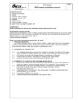
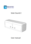
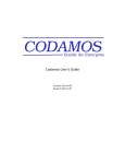
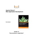
USER MANUAL
TYPE ML2013_power board
Type ML-2013
Power Board
Title
:
User guide ML2013 Power Board
Version
:
0.02
Author
:
Remco Kleine
Manufacturers of low power instruments
Date
:
July 2014
page 1
USER MANUAL
TYPE ML2013_power board
WARNING
THE FOLLOWING OPERATING INSTRUCTIONS ARE FOR USE BY QUALIFIED
PERSONNEL ONLY. TO AVOID DAMAGE OR MALFUNCTION, DO NOT PERFORM
ANY OPERATING OTHER THAN THAT CONTAINED IN THIS MANUAL. ANY
OPERATOR SHOULD BE SKILLED WITH A TECHNCAL BACKGROUND BEFORE
OPERATING THE DEVICE.
PREFACE
Congratulations!
With your purchase of the ML-2013 Power Board, for use with the type ML-2013 data logger with GPRS
Capabilities.
This manual describes the operation and (hardware) installation of the ML-2013 Power Board.
We recommend you to read this manual carefully before installation of the ML-2013.
TABLE OF CONTETS
1
Product Description ............................................................................................................................... 3
1.1
Contents of the package ............................................................................................................... 3
1.2
Warranty ....................................................................................................................................... 3
2 Editions .................................................................................................................................................. 4
2.1
PB-LI, Lithium input power edition ............................................................................................... 4
2.2
PB-DC, 8..30V DC auxiliary input power edition ......................................................................... 4
2.3
PB-PV, Solar power edition ......................................................................................................... 6
2.4
PB-PV+, Power Booster edition.................................................................................................... 6
3 Pinconfiguration ..................................................................................................................................... 8
Manufacturers of low power instruments
page 2
USER MANUAL
1
TYPE ML2013_power board
Product Description
The YDOC ML-2013-PowerBoard is an accessory to supply power the ML-2013 low power datalogger
and acts as GPRS antenna.
The PowerBoard is available in several editions:
•
•
•
•
PB-LI: As holder for a 3.6V Lithium D-size battery
PB-DC: As 8..30V DC input with holder for a 3.6V Lithium D-size backup battery
PB-PV: Solar circuit to charge 3x NiMH AA batteries
PB-PV+ : As PB-BV, but with power booster to power high power demanding sensors.
The PowerBoard fist the following ML-2013 covers:
•
•
•
•
•
COVER-LI: Blind cover and PB-LI
COVER-DC: Blind cover and PB-DC
COVER-PV(+): Cover with integrated 1Wp solar panel and PB-PV(+)
COVER-TFT-LI: Cover with integrated touch display and PB-LI
COVER-TFT-DC Cover with integrated touch display and PB-DC
Properties of the ML-2013 Power Board are:
•
•
•
•
•
•
•
1.1
Contents of the package
•
•
•
1.2
Input voltage range 8 – 30 Volts DC
3.6V Lithium D-size battery holder
Solar circuit to charge NiMH batteries.
Power output Booster
Printed GPRS antenna
RoHs Compliant
CE Compliant
ML-2013 Power Board
Power Cable (between PCB and Data logger)
Ufl-ufl antenna cable
Warranty
All YDOC instruments are warranted against defective materials and workmanship. Any questions with
respect to the warranty mentioned above should be taken up with your YDOC Distributor.
Manufacturers of low power instruments
page 3
USER MANUAL
2
2.1
TYPE ML2013_power board
Editions
PB-LI, Lithium input power edition
It’s just a printed GPRS antenna and a mounting plate for a D-size Lithium 3.6V battery. We advise to use
a SAFT-LS20H 13000 mAh battery because it can supply peak currents required for GPRS
communication.
2.2
PB-DC, 8..30V DC auxiliary input power edition
The power supply is converting the input power source to a, stable and clean, output-source of 3.6 Volts.
It is advised that when a user has a very power demanding configuration, to use this power source, to
power of the datalogger. A diode is mounted, for isolation of the (lithium battery). I.E. that no current is
drawn, accidentally, from the batteries, into the attached power supply. Your ML-2013PowerBoard has
the ideal output-voltage for cooperation with the ML-2013 dataloggers.
So:
1) When both, (lithium) battery and auxiliary power are connected, the power will be taken from the
auxiliary power only, and thus saving the battery.
2) When the power board is connected, but NOT powered, the ML-2013 datalogger will still continue
to work, and draw it’s current from the internal battery. No extra current is wasted into the power
supply, by means of the diode.
So to increase the availability of your system it is advised to use both battery and Auxiliary power.
Protection
The power board input circuit is equipped with a tranzorp of 30 Volts, this protects the connected
datalogger from high input voltages.
Beware of exposing power board to high voltages, as it will damage the fuse. Also, when the
polarity of the input-source is wrong, the fuse will blow. But, your connected datalogger is
protected in both cases.
Normally the fuse will never blow, during the lifetime of the instrument.
Manufacturers of low power instruments
page 4
USER MANUAL
TYPE ML2013_power board
Underneath, a picture is shown of a ML-2013 Power Board with Lithium Battery holder and auxiliary DC
input power.
1) Battery holder for Lithium Battery (Saft LSH-20)
2) Integrated Quad band GPRS antenna
3) Antenna Connector
4) Power output for powering datalogger (3.6 Volts)
5) 8..30 VDC auxiliary power input connector
6) Fuses for protection (battery and auxiliary)
7) Switched mode Power supply (SMPS)
Manufacturers of low power instruments
page 5
USER MANUAL
2.3
TYPE ML2013_power board
PB-PV, Solar power edition
This options enables the use of solar power. It is designed to use with
the YDOC solar panel housing.
It has a battery holder for 3 AA type NiMH batteries. These batteries are
charged from the solar panel and, due to the dimension of the solar
panel, will never be overcharged.
Battery undervolts protection
It has a Battery low protection which triggers when the battery voltage
gets below 2.9 Volts. When this happens, the batteries will be disconnected from the output (from the
datalogger), so the batteries won’t be damaged due to total discharge. There is a hysteresis which
prevents the system from “flipping” on and of all the time. The batteries are re-connected to the power
output when the battery-voltage gets above the threshold + hysteresis. So, the datalogger will work again.
2.4
PB-PV+, Power Booster edition
As PB-PV but wit power booster. This feature is used to “boost” the Sensor Power signal from the
datalogger. It is used for powering very high power demanding sensors. It also provides in two, user
selectable, output voltages. The system can boost the normal 12 Volts /100mA Sensor Power signal from
the datalogger into a high power 12 Volts/400 mA (500 mA peak) or 24 Volts / 170 mA. The user can
select his output voltage by using a solder jumper.
By factory default, the output voltage is set to 12 Volts. This high power or “boosted” signal is exactly in
sync with the Sensor Power signal of your ML-2013 series Datalogger. The current is drawn directly from
the 3 AA type NiMH batteries. This has the advantage that the datalogger itself is NOT loaded at all. The
main current flow will be from the Power Board Only.
Output Voltage Configuration
SJ1
Voltage
Open
12 V
Closed
24 V
Beware!
The Power Booster option is only available in
combination with the solar / NiMH option. It is NOT
possible to use it with the Lithium D cell battery.
Simply because this battery is not capable of
providing such high currents. The NiMH batteries
are the only ones that are suitable for this purpose
Manufacturers of low power instruments
page 6
USER MANUAL
TYPE ML2013_power board
Underneath a picture is shown of the Solar and PowerBoost option. Combined together a very powerful
system can be made. i.e. a 24 volts sensor, powered by the sun.
1) Battery Low Protection Circuit
2) Negative Solar Panel input terminal
3) Quad band GPRS antenna
4) Antenna Connector
5) Power Output connector (to datalogger)
6) Sensor Power input Connector
7) Power Boost Output Connector
8) Positive Solar Panel input terminal
9) Battery Holder for 3 AA type NiMH batteries
10) Power Booster Circuit
Manufacturers of low power instruments
page 7
USER MANUAL
3
TYPE ML2013_power board
Pinconfiguration
Connector
X1
X1
X1
X1
X1
X1
X2
X2
X2
X3
X3
X4
X4
TP1
TP2
Pin
1
2
3
4
5
6
1
2
3
1
2
1
2
Function
GND
GND
GND
Power_Out
Power_Out
Power_Out
Sensor Power Input
GND
N.C.
Power Supply +
Power Supply Aux Power Input +
Aux Power Input Solar Charge input +
Solar Charge input -
Manufacturers of low power instruments
Description
Value
Comments
0V
Sensor Power signal to 0V
power 12 Volts or 24 Volts 0V
sensors, multiple terminals 12V / 24V
for connecting multiple wires 12V / 24V
12V / 24V
12 V
Sensor Power input , must
be connected to Sensor 0V
Power output of datalogger N.C.
Molex connector
Power output for powering 3.6 V
ML2013 series datalogger 0V
8 .. 30 V
Auxilary power input
0V
Must be soldered
Must be soldered
page 8
USER MANUAL
TYPE ML2013_power board
Specifications
Power Supply
Input Range
Type of Power
Power
Sensor Power Output
Protection
Output Voltage
Output Current
Charger Circuit
Discharge protection
Bypass Diode
General Enviroment
Temperature
Humidity
Electrical
SMPS
Switch Frequency
Quiesent Current
Peak Current
Max. Input Voltage
Min. Input Voltage
Connector
Galvanic Isolation
Ripple & Noise
CE Complient
Rohs Complient
Dimensions
WXDxH
Weight
Netto Weight
8 ~ 30 Vdc| Solar 5V |Lithium 3.6 Volts
Lithium Battery | External DC | NiMH battery/Solar Panel
Output Voltage
Output Current
3.6 V
1000 mA
Output power
3.6 W
12 Volts / 24 Volts selectable by solder jumper
400 mA / 170 mA
yes, @ 2.9 Volts
yes
Operating: -30 ~ + 65 °C; Storage -40 ~ +75 °C
5 ~ 100 % RH
yes
200 kHz
100 uA
1.8 A
30 V
5V
Molex 22-27-2021
No
1% pk-pk, 20 MHz bandwidth
Yes
Yes
107 mm X 109 mm X 35 mm
110 Grams
Manufacturers of low power instruments
page 9