Download USER Manual
Transcript
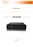
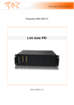
LinkGate SIP32/PRI manuel 1 Overview .............................................................................................................................. 7 1.1 Telephone Cost Cuts ............................................................................................................. 7 1.2 Safety Precautions ................................................................................................................. 7 2 Possibility of switching ........................................................................................................... 8 2.1 Analyze Incoming Calls .......................................................................................................... 8 2.2 Analyze Outgoing Calls .......................................................................................................... 8 3 Device description ................................................................................................................. 9 3.1 CPU board ............................................................................................................................. 9 3.1.1 VoIP ............................................................................................................................ 9 3.1.1.1 General ....................................................................................................................... 9 3.1.1.2 Technical Data ............................................................................................................ 9 3.1.2 ISDN ........................................................................................................................... 9 3.1.2.1 Technical Data .......................................................................................................... 10 3.1.3 LED Value ................................................................................................................. 10 3.1.4 RJ45 pin setting ........................................................................................................ 11 3.2 Peripheral Board .................................................................................................................. 12 3.2.1 GSM peripheral Board .............................................................................................. 12 3.2.1.1 Technical Data .......................................................................................................... 12 3.2.1.2 Features for carriers (On demand)............................................................................ 12 3.2.1.3 SMS server ............................................................................................................... 13 3.2.2 Analog Board ............................................................................................................ 13 3.2.2.1 Technical Data .......................................................................................................... 13 3.2.2.2 Description of FxS card ............................................................................................. 14 3.2.2.3 Description of Analog FxO card ................................................................................ 14 4 Gateway settings ................................................................................................................. 15 4.1 File ....................................................................................................................................... 15 4.1.1 New ........................................................................................................................... 15 4.1.2 Open ......................................................................................................................... 15 4.1.3 Save .......................................................................................................................... 15 4.1.4 Save as ..................................................................................................................... 15 4.1.5 Close ......................................................................................................................... 15 4.1.6 Download from Gateway ........................................................................................... 15 4.1.7 Upload to Gateway ................................................................................................... 16 4.1.8 Upload to Gateway Without Network Setting ............................................................ 16 4.1.9 Download CDR ......................................................................................................... 16 4.1.10 Recent file ................................................................................................................. 16 4.1.11 Quit ........................................................................................................................... 16 4.2 View ..................................................................................................................................... 16 4.2.1 Toolbar ...................................................................................................................... 16 4.2.2 Status ........................................................................................................................ 16 4.3 Connection ........................................................................................................................... 17 4.4 Options ................................................................................................................................ 17 4.4.1 Communication ......................................................................................................... 17 4.4.2 Language .................................................................................................................. 17 4.4.3 Password .................................................................................................................. 18 4.4.4 Date/Time ................................................................................................................. 18 4.5 Service ................................................................................................................................. 19 4.5.1 System Information ................................................................................................... 19 4.5.2 General reset ............................................................................................................ 20 4.5.3 Update firmware ........................................................................................................ 21 4.5.4 Module reset ............................................................................................................. 21 4.5.5 Update Announcements............................................................................................ 21 4.5.6 System Monitor ......................................................................................................... 22 5 Configuration ...................................................................................................................... 23 5.1 System ................................................................................................................................. 23 5.1.1 General ..................................................................................................................... 23 5.1.1.1 Time synchronization ................................................................................................ 24 5.1.1.2 Mobility Extension ..................................................................................................... 25 5.1.1.3 Announcements ........................................................................................................ 25 5.1.2 Network ..................................................................................................................... 25 5.1.3 Alarm indication ........................................................................................................ 26 5.1.4 Call detail record (CDR) ............................................................................................ 27 5.1.5 Credits....................................................................................................................... 28 5.1.6 SMS Messages ......................................................................................................... 28 5.2 ISDN .................................................................................................................................... 29 5.2.1 Common ................................................................................................................... 30 5.2.2 Lines ......................................................................................................................... 32 5.2.2.1 Expert Settings.......................................................................................................... 35 5.2.3 Synchronization ........................................................................................................ 35 5.3 Analog Lines ........................................................................................................................ 36 5.3.1 Subscriber_FXS ........................................................................................................ 36 5.3.2 Trunk_FXO ............................................................................................................... 37 5.4 Peripheral Cards .................................................................................................................. 38 5.4.1 Cards Type Configuration ......................................................................................... 38 5.4.2 Cards ........................................................................................................................ 38 5.4.2.1 GSM Modules ........................................................................................................... 39 5.4.2.2 Card of Analog Subscriber_FXS ............................................................................... 42 5.4.2.3 Card of Analog Trunk_FXO....................................................................................... 42 5.4.2.4 Combined Card of Analog Subscriber_FXS/Trunk_FXO .......................................... 43 5.5 VoIP ..................................................................................................................................... 43 5.5.1 VoIP Common........................................................................................................... 43 5.5.1.1 SIP Protocol .............................................................................................................. 44 5.5.1.2 RTP Protocol............................................................................................................. 44 5.5.1.3 NAT Traversal ........................................................................................................... 44 5.5.2 VoIP Users ................................................................................................................ 45 5.5.2.1 SIP User Account ...................................................................................................... 46 5.5.2.2 SIP Account Advanced Voice Options ...................................................................... 47 5.5.3 VoIP Trunks .............................................................................................................. 48 5.5.3.1 SIP Trunk Account .................................................................................................... 49 5.5.3.2 SIP Trunk Advanced Options .................................................................................... 50 5.5.3.3 SIP Account Advanced Voice Options ...................................................................... 51 5.6 Groups Configuration ........................................................................................................... 53 5.6.1 Incoming Group ........................................................................................................ 53 5.6.1.1 GSM Incoming Group ............................................................................................... 53 5.6.1.2 VOIP Incoming Group ............................................................................................... 56 5.6.1.3 Subscriber (FXS) Incoming Group ............................................................................ 57 5.6.1.4 Analog Trunk FXO Incoming Group .......................................................................... 57 5.6.2 Outgoing groups ....................................................................................................... 57 5.6.2.1 GSM outgoing groups ............................................................................................... 58 5.6.2.2 VOIP Outgoing Group ............................................................................................... 58 5.6.2.3 Subscriber (FXS) Outgoing Groups .......................................................................... 58 5.6.2.4 Analog Trunk Outgoing Group .................................................................................. 59 5.7 LCR (Least Cost Routing) .................................................................................................... 59 5.7.1 CLIP Table ................................................................................................................ 60 5.7.2 Routing Table............................................................................................................ 60 5.7.2.1 Default routing profile ................................................................................................ 61 5.7.2.2 Routing profile ........................................................................................................... 63 5.8 CLIP from GSM.................................................................................................................... 63 5.9 Mobility Extension ................................................................................................................ 63 5.10 Working Hours ..................................................................................................................... 64 6 Diagnostics ......................................................................................................................... 66 6.1 ISDN lines ............................................................................................................................ 66 6.2 ISDN lines credit .................................................................................................................. 67 6.3 Cards Status ........................................................................................................................ 68 6.4 GSM modules credit ............................................................................................................ 70 6.5 GSM Modules In Use ........................................................................................................... 70 6.6 GSM Modules Statistics ....................................................................................................... 72 6.7 VoIP status........................................................................................................................... 73 6.7.1 SIP Trunks ................................................................................................................ 73 6.7.2 SIP Users .................................................................................................................. 74 7 Appendix ............................................................................................................................ 75 7.1 Description of cdr line .......................................................................................................... 75 7.2 Description of status for peripheral board ............................................................................ 76 7.2.1 The Status of GSM Cards ......................................................................................... 76 7.2.2 The Status of Analog Modules .................................................................................. 78 7.3 Description of Alarm message from GSM modules.............................................................. 79 7.4 Technical Conditions for Installation ..................................................................................... 80 7.4.1 Subrack ............................................................................. Erreur ! Signet non défini. 7.4.2 GSM .......................................................................................................................... 80 7.4.3 PRI Interface(s) ......................................................................................................... 80 7.4.4 Temperature ............................................................................................................. 81 7.4.5 Remote Control Line types........................................................................................ 81 ! Important! Before you start installing this product, check whether the delivery is complete and read this manual thoroughly. Warning!!! This construction solution is prepared to be placed in the rack. First it is necessary to connect the protective earthing clip. Make sure that the power supply LinkGate PRI-SIP32 is in the position 220-240V. The manufacturer cannot be held responsible for any damages that occurred due to incorrect use of this product in contradiction to this manual. The guarantee terms do not cover damages of the product caused by rough handling, incorrect storage or by exceeding the quoted technical parameters. LinkGate PRI-SIP32 is a compact highly sophisticated system. It supports full remote supervision and configuration via an IP network or USB port. The system has been designed and works with a lot of highly sophisticated functions, which make it fully client-oriented and highly reliable in cooperation with both GSM networks and ISDN. Configuration alterations can be made without resetting, i.e. under full operation. Basic general features • • • • • • • • • • • • • • • • • GSM Gateway equipped with 4 GSM channels, upgradeable to 32. VoIP - Standard SIP client, can be easily integrated with most of iPBX market. Analog line/trunk with support for CLIP and tax pulses 12/16 kHz Incoming and outgoing calls managed by groups. (SIM card groups) Integrated LCR: allow forwarding of outgoing calls via a group of SIM card according to caller’s number and receiver’s number. Integrated router: allow call forwarding trough PSTN PRI access. Voice Call Back: allow a worker to be callback by the gateway and make a free call from his mobile phone. System credits. Time synchronization. SMS Server: allow sending and receiving of SMS. Mobility extension. Smart Call Back: The gateway saves in memory all outgoing missed calls. So, if the mobile which was called call back, LinkGate PRI-SIP automatically forward the call to the initiator internal phone. DISA When calling a SIM card in the gateway, LinkGate PRI-SIP can send dial tone and allow the caller to dial internal number. Advanced credit management for each SIM card, according to remaining credit and day of credit restoration. CDR: Call Detail Record. Statistics for use of GSM modules. Configuration by PC with USB or Ethernet connection. 1 Overview LinkGate PRI-SIP32 is specially designed for big companies, call-centres and companies whom GSM traffic is high. This Gateway is an ideal solution for decreasing costs of fixed-to-mobile and mobile-to-fixed communication ( VoIP, Analog line/trunk, ISDN PRI). LinkGate PRI-SIP32 allows connecting incoming and outgoing calls among ISDN network, VoIP network and GSM/UMTS network. LinkGate PRI-SIP32 may also decrease costs of call termination, when connected to alternative carrier equipment. Its easy way for installing and programming, its upgradeability and flexibility make absolute must product. 1.1 Telephone Cost Cuts This device considerably saves telecommunications fees because normally calls between fixed and mobile networks are charging with the interconnection fees that cause this type of call is the most expensive for the user. In general, the gateway converts outgoing call type PSTN -> GSM to call type GSM -> GSM and incoming call GSM -> PSTN to GSM -> GSM. All parameters needed for routing to reduce telecommunications charges can be set via the configuration software and implemented to device. 1.2 Safety Precautions It is prohibited to use the gateways (as any transmitters) in areas where explosives are used, such as quarries. It is prohibited to use the gateways at petrol stations where mobile telephones are also prohibited. GSM/UMTS devices ( as GSM phones) may affect sensitive life-saving devices in medical centers. Therefore, it is forbidden to use gateways, in such facilities. In general, any prohibition regarding mobile phones based on RF energy radiation applies to GSM/UMTS devices too. If necessary, the GSM gateways may be installed at a safe distance from the prohibited area and connected with the original place through an Ethernet cable. 2 2.1 Possibility of switching Analyze Incoming Calls Incoming calls from the source network (PSTN, VoIP, GSM) can be sent to the destination network following the specified routing rules either directly specify the destination number (usually a PBX subscriber numbers), or you can also dial caller's subscriber numbers of PBX or other networks by DISA. The tones or announcements (you can enter them ) help to inform the calling party. 2.2 Analyze Outgoing Calls LinkGate PRI-SIP analyzes outgoing calls from PBX to the destination networks by the specified routing rules, consider the specific assignment of SIM to mobile operator, the current credit and other features necessary to make connections cheapest way. The public ISDN, VoIP and PSTN line can be connected to LinkGate PRI-SIP and it is possible outgoing connection not only to the GSM network but also the fixed public network PSTN. 3 Device description The system is integrated in a 19“ sub rack of the height of 3U and depth 360 mm. The front side is open, equipped with guides for plug-in boards with front panels. 3.1 CPU board The CPU board contains a powerful processor system controlling the whole system. The board is designed on a 4-layer PCB of the size of 280x100mm. Threre are an USB interface, an Ethernet connector (10/100 Base-T) and three RJ45 connectors with pair of E1 line status LED indicators located on the front panel. 3.1.1 VoIP CPU board contains the VoIP module with the digital signalling procesor. Configuration of the VoIP module is completely managed by CPU and made via our Configuration SW (Link PRISIP_x.x.x.x.exe). Firmware for VoIP module is part of the firmware for the whole gateway and upgrade the firmware will automatically upgrade the VoIP if necessary. The Ethernet port works with media packets (RTP) and signaling packets (SIP). 3.1.1.1 General VoIP interface up to 32 channels Standard SIP client, can be easily integrated with most of IP PBX market. SIP server, can substitute to IP PBX and register IP phones on LinkGate PRI-SIP 3.1.1.2 Technical Data Signaling: SIP v2 Number of channels: 32 Codecs: G.711u, G.711a, G.726, GSM VAD (Echo cancellation) Protocols: IP, TCP, UDP, HTTP, TELNET, SIP, RTP Interface: LAN 10/100 Base-T, RJ45 Compatible: All SIP v2 IP PBX. Validated on Cisco Call Manager, Alcatel OMNI PCX, Asterisk, Nexspan, Panasonic… 3.1.2 ISDN There are three primary rate (PRI, E1) ISDN interfaces and PCM bus switching and timing circuit. Recommended connection: E1-A interface is designed for connection to PBX and LCR functions is activated on this port. E1-B interface is designed for connection to PSTN (default: all calls from this port will be routed to E1-A port ) E1-C interface is according to customer's choice Each of these interfaces can be configured as TERMINAL or as NETWORK independently and each of these interfaces can be configured as an input of clock synchronization with defined priority. 3.1.2.1 3.1.3 Technical Data • • 3 RJ45 ports useable in TE or NT mode Signalling EURO ISDN EDSS1 (Q.931), QSIG • Synchronisation Master / Slave • CRC4 enabled or disabled • Channel blocking • RJ45 Pin setting • TEI and HDLC channel selection • Order of synchronisation adjustable • Direct Access (Channel / GSM Module) • Call progress tone • Long Haul LED Value Description of LED E1 value GREEN YELLOW LIGHT DARK Connection is OK FLASH DARK No data link connection (Layer 2) LIGHT SOMETIMES FLASH Description Connection is OK, lines is not synchronized (slip) Description of LED E1 value GREEN YELLOW Description DARK FLASH Signal is present but it is not OK DARK LIGHT No signal DARK DARK Line is not in configuration Description of LED LAN/VoIP value 3.1.4 GREEN YELLOW Description LIGHT DARK Connection is OK LIGHT FLASH Connection is OK, LAN is under way RJ45 pin setting Swapping of the transmitting and receiving connector pair can be made either automatically according NT or TE configuration setting or manually according user setting. For this selection is not need any jumpers on CPU board – all can be made using Gateway configuration software(see Expert Settings). 3.2 Peripheral Board 3.2.1 GSM peripheral Board • Incoming and outgoing calls managed by groups of SIM cards. • 1 to 32 incoming groups • PIN Code • Credit management with remaining credit, setting of counts (second) and day of credit restoration. • CLIR 3.2.1.1 Technical Data • From 4 to 32 GSM channels (4 by card) • Band: 900/1800MHz • GSM module: Siemens TC35I • Power: 2W • SIM card: 3V • Antenna: SMA female, Impedance 50 Ω • Echo cancellation 3.2.1.2 Features for carriers (On dem and) • GSM module SIM-locked • Changes on dialled number on GSM network ( add, remove digits) The GSM board contains four GSM modules (f.e. Siemens TC35i), circuits for their connection to the PCM bus, and DTMF receivers. The board is designed on a 4-layer PCB of the size of 280x100mm. Four antenna connectors and 4 GSM status indicators are located on the front panel. Status of indication LED on Gateway Switch LED Colour Description NONE Module is Not configured GREEN LIGHT Connection in process (call) Module logged in the network, rest condition on Signal quality flash: 1 per 4 sec the lowest 5 per 4 sec the highest GREEN FLASH RED LIGHT GSM module is not presented RED FLASH other ERRORs see Error states ORANGE LIGHT SMS communication ORANGE FLASH 3.2.1.3 ERROR fast flash Initialization slow flash No Network SM S server USB connector of peripheral board can be used as the SMS server. Any module can be used as the SMS server. If SMS communication is working you can see status of Module Card in Diagnostics. 3.2.2 Analog Board There are 3 type of analog boards • 4 channels analog line board • 4 channels analog trunk board • combined 2 analog line, 2 analog trunk board RJ-11 connector for analog line 3.2.2.1 Technical Data • Transmition and reception DTMF signal • DTMF and Pulse dialing are supported • Call Progress tone detection and generation • CLIP is supported by FSK (V.22 or Bell 202) or DTMF • Transmition and reception Subscriber Pulse Metering (12 kHz /16 kHz) • Line impedance is configurable by hardware (default 600 ohms) 3.2.2.2 Description of Fx S card Subscriber_FXS card contains 4 analog lines, or 2 analog lines and 2 analog trunks if the card is combined. Status of indication LED on BlueGate ISDN FCT LED Color 3.2.2.3 Description NONE Idle GREEN LIGHT Connection in process (call) RED FLASH Alerting Description of Analog FxO card Status of indication LED on BlueGate ISDN FCT LED Color Description NONE Idle RED FLASH NO loop current ORANGE LIGHT Connection in process 4 Gateway settings Link PRI-SIP Config-x.x.x.x.exe is the Configuration SW. This program allows you to configure and control your gateway. In top menu you can set all parameters through items File, View, Connection, Options and Service. First you install proper interface in menu Option Interface to configure other items. Some parameters you can set through the use of item in toolbar ( New, Open, Save, Download from Gateway Switch_VoIP and Upload to Gateway Switch_VoIP ). 4.1 File Section File allows you to define New File of configuration and save it as a *.cfg or open an existing configuration file. After setting configuration you can save it or upload to gateway. It contains an item for program end too. 4.1.1 New In this pane you can create the new configuration and load default setting in the tree and set or change it. 4.1.2 Open Program opens a file from a folder selected by you. 4.1.3 Save Program saves a file of configuration. 4.1.4 Save as Program saves the file into a folder selected by you. 4.1.5 Close Terminates setting configuration. 4.1.6 Download from Gateway If you extract from Menu File this item you can download last-saved configuration file from gateway. 4.1.7 Upload to Gateway This item allows you to save your configuration file to gateway. 4.1.8 Upload to Gateway Without Network Setting This item allows you to save your configuration file to gateway without the Name and the Network setting. 4.1.9 Download CDR If you extract from Menu File this item you can download call detailed records (*.csv) from gateway. Description of cdr line is in Appendix. 4.1.10 Recent file There are recent saved files of configuration (last 6). 4.1.11 Quit Terminates the program. 4.2 4.2.1 View Toolbar Display or hide toolbar with items New, Open, Save, Download from Gateway, Upload to Gateway All, or Upload to Gateway Without Network and information about program. 4.2.2 Status Display or hide status line on the bottom of pane. 4.3 Connection Section Connection allows you to connect or disconnect the USB or LAN port. 4.4 Options This section is used for setting Communication, Password, Language and Date and Time. 4.4.1 Communication Select properly communication • USB virtual COM port • Choose proper COM port, which makes communication of gateway with your PC. • TCP/IP Set IP adress and TCP port. 4.4.2 English. Language 4.4.3 Password You can set or change password for access to gateway. Password is saved in Gateway. 4.4.4 Date/Time You can set or change date and time in the gateway. If you tick off System->General->Time synchronization there will appear the text "The last successful synchronization with the Internet..." 4.5 Service Section Service displays System Information and contains commands for the gateway as General Reset, Update Firmware, Module Reset, Update announcements and allows display System Monitor (available only if the GSM Gateway is connected). 4.5.1 System Information This item displays System information. 4.5.2 General reset System restarts the gateway and initializes all Gateway boards (the gateway communication is not discontinued but all current calls and SMS to be sent are terminated!). 4.5.3 Update firmware System writes firmware (file *.LMF) into Gateway. Warning! If you can write firmware from network and the connection is unstable it is possible failure of update firmware. 4.5.4 Module reset You can choose the GSM module to reset it. 4.5.5 Update Announcements There are loaded default announcements in the gateway, which can be updated to suit your needs. Parameters of wav file Sample Rate 8000 samples/s Channels mono Resolution 8 bit/sample Audio format G.711 A-law Max length 32 second Select the type of the announcement to update and system writes Announcements (file *.wav) into Gateway. You can turn on/off the announcements as you like in System->General->Announcements. 4.5.6 System Monitor This pane is used for storing traces from ISDN layers (sending and receiving messages) for possible check in case of problems. 5 Configuration In this pane you can set the gateway's parameters as System, ISDN, Analog Lines, Peripheral Cards, VoIP, Groups Configuration, LCR (Least Cost Routing), CLIP from GSM and numbers for Mobility Extension. 5.1 System This pane allows you to assign General parameters, to set network parameters (Network) , parameters for Alarm Indication, CDR, Credits, parameters for transmission of received SMS messages 5.1.1 General In this section you can assign name of your equipment in Gateway Identification and set Time synchronization, Mobility Extension, Announcements and VoIP. 5.1.1.1 Tim e synchronization You can set to synchronize Time with the Internet time server, Time Zone and Automatically adjust clock for the European Summer Time. If you tick off Automatically synchronize the last successful synchronization with the Internet appears in (Options->Date/Time). To synchronize time with the Internet time server should be set at least two network parameters: default gateway DNS server. 5.1.1.2 M obility Extension o Off Mobility Extension is disabled. o On for defined users Mobility Extension is allowed only for users defined in List of GSM numbers in CLIP from GSM, other users cannot use this function. o On global (for all users) Mobility Extension is allowed for all GSM users. The Mobility Extension is the service that turns your call to other user. Example: You have one call and you need to consult with other user. By pressing "*" on your mobile phone you hold your first call. (Hold allows you to park a call until it can be transferred or managed.) You can dial the number of other user and the hold user is listening music. When other user answers the call (or is ringing) you can transfer this user with the hold user by hanging up your mobile phone. If you have two calls on your mobile phone you can retrieve to hold user and disconnected other user by pressing "*" . When other user does not answer the call you can retrieve to hold user by pressing "*". If you dial wrong number of other user you can retrieve to hold user by pressing another "*". 5.1.1.3 Announcem ents o Send announcement for outgoing calls to GSM The user of GSM module will hear the announcement at the begin of the call. o Send announcement for incoming calls from GSM The user of GSM module will hear the announcement at the begin of the call. You can choose o PBX user hears silence or o PBX user hears announcement. If the user hears the announcement you can set time for transmission of beeps during a call from 0 - 240 seconds. Default "0" means no beep. 5.1.2 Network In this section you can set parameters as IP address, Subnet mask, Default gateway, number of the Port and DNS servers. Note: Default gateway and DNS server should be set at least to synchronize time with the Internet time server if you set System->General->Time synchronization . 5.1.3 Alarm indication Gateway will send alarm message to assigned GSM number or IP address in case of trouble with some GSM module. Description of Alarm Message is in appendix. o GSM numbers for SMS alarm indication In this section you can set max 5 numbers for SMS message. If this numbers aren't filled alarm messages are not sent. o Address for IP alarm indication You can set the address for IP alarm indication and the number of port. You can type the IP address in two formats for example 192.168.1.14 or www.my_name.com (in this case you must set DNS server in Network Setting for Remote access) and supervisory program will send the alarm message in syslog protocol. The port number has max 5 digit. If this address isn't filled alarm messages are not sent. o SMTP account for E-mail alarm indication You can set account for e-mail alarm indication 5.1.4 Call detail record (CDR) The gateway sends Call Detail Record (CDR) containing details of a call passed through it. Description of cdr line is in Appendix except the first column, which is heading described in syslog protocol. o IP address for CDR transmission You can set the address for IP of CDR transmission and the number of port. You can type the IP address in two formats for example 192.168.1.14 or www.my_name.com (in this case you must set DNS server in Network Setting for Remote access) and supervisory program will send the CDR message in syslog protocol. If this address isn't filled CDR messages are not sent. o Timeout (minutes) You can set period for transmission of CDR. The value is from 1 to 65534 minutes. o Store CDR for You can choose storing Answered and/or Unanswered calls 5.1.5 Credits The Gateway Switch_VoIP sends Credits from GSM or ISDN lines or both. o IP address for Credits transmission You can set the address for IP of Credits transmission and the number of port. You can type the IP address in two formats • for example 192.168.1.14 • or www.my_name.com (in this case you must set DNS server in Network Setting for Remote access) and supervisory program will send the Credits message in syslog protocol. If this address isn't filled Credits messages are not sent. o Select credits to send You can choose GSM modules or ISDN lines or both to send credits. o Credits sending period and time You can set period and time for sending credits. 5.1.6 SMS Messages o IP address for received SMS messages transmission The gateway sends received SMS message if Address and Port number is filled. You can set the address for IP of received SMS messages and the number of port. You can type the IP address in two formats for example 192.168.1.14 or www.my_name.com (in this case you must set DNS server in Network Setting for Remote access) and supervisory program will send the received SMS message in syslog protocol. If this address isn't filled received SMS messages are not sent. o SMS notification for unanswered call SMS text You can type the text (max. 160 characters), which is sending to the user of GSM network if the call is unanswered. If text of SMS message contain string ?????? (6x question mark) this string will be replaced by the extension of caller. o Select GSM modules allowed to send SMS messages Each outgoing SMS message (except the the Alarm messages) will be sending by GSM modules which you select. You can select All or separately GSM modules. o SMS server When using the SMS-Mail application the GSM gate allow transmission or receipt of SMS messages. 5.2 ISDN This pane contains setting of ISDN line. You can set Common properties, options for each Lines and Synchronization. 5.2.1 Common o Dial tone No dial tone Gateway will not send any dial tone towards PBX on empty SETUP (in case that receive SETUP message without called party number). Continuous tone Gateway sends continuous dial tone. Tone Morse A Selection of type of dial tone (330 ms pulse, 330 ms pause, 660 ms pulse, 660 ms pause). o Wait for next digit Set time (1-60 seconds) to wait for next digit. This timeout causes the end of dialling from PBX. o Time to save smart callback Set time (0-48 hours) for saving callback information in smart callback table. ‘0’ means that smart callback function is disabled. o Channel association 1:1 with GSM modules Each channel from PBX has fix channel of GSM module. For example: 1.voice channel is connected to 1. GSM module and vice versa, GSM modules 31, 32 are unused. o Call progress tone User of PBX will hear progress tone or will not it. o CLIP modifications Substitute '+' for GSM CLIP in international format (+420 -> 00420) Supply '+' in international format or not. Cut prefixes '+', '0' and '00' in GSM CLIP (00420 -> 420) Default - this function is not use. Country prefix for change GSM CLIP from international to national format You can set the national format. For example: You type 420 If you tick off "Cut prefixes...." 004209x -> 9x If you do not tick off "Cut prefixes...." 004209 -> 09x o Timeout if extension does not answer Time in seconds. Default is 30 seconds. o Delay before Alerting Time in seconds or R. Default is 0 seconds. R means that gateway generates its own ring back tone in case that Call progress tone is OFF. If Call progress tone is ON R is no use. o Send CONNECT together with ALERTING If you tick off this item the message ALERTING and CONNECT will be sending together. Only for call from PBX to GSM network. o Condition for blocked PBX line You can set number of SIM cards, or number of SIM cards with poor signal as well as define the value of poor signal when the line will be blocked. Number of SIM cards not logged (0-32) Default - 0 - this function is not use. Number of SIM cards with poor signal (0-32) Default - 0 - this function is not use. Parameter for poor signal definition (-113 dBm - -51dBm) You can set the level of poor signal (only odd-numbered). o ISDN cause if GSM modules/groups are busy You can set cause (1-127) if the GSM modules/groups are busy. Default value is cause 3 (No route to destination). 5.2.2 Lines In this section you can set options for each line (PBXE1-A, PSTNE1-B, E1-C, E1-D). . o Protocol In this section you can set protocol. Signalization You can define type of signalization: - DSS1 (ITU-T Q.931) - Q-SIG - disabled. You can configure the line as network (NT) or terminal (TE). o L1 Parameters CRC4 Parameter for activating/deactivating CRC of Layer 1 on PRI ISDN interface. o L3 Parameters It defines way of occupation of B-channels on PRI interface. Upwards channel selection (A side) Gateway will occupy channels from channel 1 to 32. Downwards channel selection (B side) Gateway will occupy channels from channel 32 to 1. Cyclic channel selection Gateway will occupy channels from last engaged +1/-1 channel. o Channel’s Blocking This setting allows to block unused channel. o Credit setting Day of credit restoration (1-31) Set day of month when credit is automatic restoring. Week/Day of credit restoration (1-31) Set week in month (1-4) and day of the week (Monday - Sunday) when credit is automatic restoring. Day of weekly credit restoration (Monday) Set day of the week (Monday) when credit is automatic restoring. There are 3 different credits. You can set each of them. Credit to restore Set amount of credit (tariff) in minutes, which is restoring. If this credit is spent the outgoing call via E1-line which used this credit can be blocked (if you set Block outgoing call when credit is spent) or it will be routed to GSM network according to CLIP Table and Routing Table. Max value of credit is 44640 min (one month). Credit without limit is signified "0". You can see it in pane of Diagnostics (ISDN lines credit). Maximal remaining credit Set amount of remaining minutes, which you have not spend yet, these will be rolled over to the next month and added to your credit. First count (in seconds) First count (in seconds) Next count (in seconds) Length of the next period (1 to 250 seconds) Parameters First count and Next count are used for account of the real length of the call from the view of the carrier. Example 1: If the call is charged per second - set both parameters to 1. Example 2: If you are charged immediately after answering a call for the whole first minute and then second by second - set first count to 60 and next count to 1. Proper setting of these parameters helps you to keep real record of the minutes spent and charged for each E1-line. Block outgoing call when credit is spent. Outgoing call is default blocked when credit is spent. The next outgoing call will be routed to GSM network according to CLIP Table and Routing Table. 5.2.2.1 Expert Settings This pane contains other parameters of lines. This setting is not recommended to change. L1 Parameters Parameters for L1 layer. Long Haul This setting is not recommended to change (only the Gateway is placed far away from PBX approximately 300m and PBX takes part of it). RJ45 pin setting You can choose from 3 options of RJ45 pin setting: According to the protocol, Always TE or Always NT. L2 Parameters This setting is not recommended to change. TEI selection (0-127) Gateway identification address (0 by default, 127 max.) Signalling HDLC channel (1-31) Gateway identifies HDLC channel (16 by default). 5.2.3 Synchronization You can set a synchronization clock accordance order in table Order of synchronization. You can added or reduce any of E1 links and move up or down their sequence. First line in the pane Order of synchronization has the highest priority. 5.3 Analog Lines This pane contains setting of Analog line in LinkGate PRI-SIP. You can set Subscriber_FXS and Trunk_FXO properties. 5.3.1 Subscriber_FXS In this section you can set transmitted Metering pulses 12 or 16 kHz. 5.3.2 Trunk_FXO In this section you can set parameters of Trunk. o Dialling mode Choose an option pulze or DTMF o Line Seizure Line Seizure means that when the dialler needs to make an important alarm call, it will hang up and disconnect anyone else from using the telephone line so that a clear line is available for use by alarm call. and waiting time (1 - 30 seconds) o Start of call time of busy tone detection and line reversal o End of call detection of busy tone and its minimum length, loop current detection and line reversal o Received Metering pulses 12 or 16 kHz o Length of flash signal (40 - 1275 milliseconds) 5.4 Peripheral Cards You can set Type of Cards Type of Cards and all parameters for individual Card. 5.4.1 Cards Type Configuration You can set optional type of the peripheral card (GSM, Analog Subscriber_FXS, Analog Trunk_FXO or Analog Combined (FXS/FXO). 5.4.2 Cards This section defines properties for the each type of cards. There are displayed 4 modules for each LinkGate ISDN FCT(max. 4 GSM modules x 8 SIM cards). You can set properties of individual cards (GSM, Analog Subscriber_FXS, Analog Trunk_FXO or Analog Combined (FXS/FXO). 5.4.2.1 GSM M odules This section defines assignment of GSM modules to GSM group and allows setting SIM card. o Configuration Disable You can define unused GSM card if you tick off Disable. Echo cancellation You can choose ON/OFF echo. Roaming You can permit or forbid to register GSM module to roaming. CLIR Number of calling subscriber is restricted or not. AMR This parameter can be used to control the usage of the feature "Adaptive Multi Rate". You can choose enabled or disabled AMR. Note: Only for module MC55 DTMF retransmission You can choose retransmission of DTMF digits coming from PBX user as the message to GSM network. Only for call from PBX to GSM network. o Volume It is possible to set volume from GSM->ISDN and from ISDN->GSM. Range of volume is from -6 dB to +12 dB. o Assignment to GSM groups It is possible to set each module (1-32) and assign its GSM Incoming Groups, its GSM Outgoing groups and second outgoing group or no (default). o SIM card 1 In this window we can set: PIN code Set number of PIN code for SIM card. Length of PIN code is 8. You can enter PIN code twice. After 2 wrong setting you must remove SIM card from Gateway and enter proper PIN code. Day of credit restoration (1-31) Set day of month when credit is automatic restoring. Week/Day of credit restoration (1-31) Set week in month (1-4) and day of the week (moneylender) when credit is automatic restoring. There are 3 different credits. You can set each of them. Credit to restore Set amount of credit (tariff) in minutes, which is restoring. If this credit is spent GSM module is blocked for outgoing calls. Max value of credit is 44640 min (one month). Credit without limit is signified "0". You can see it in pane of Diagnostics (GSM Modules Credit). Maximal remaining credit Set amount of remaining minutes, which you have not spend yet, these will be rolled over to the next month and added to your credit. First count (in seconds) First count (in seconds) Next count (in seconds) Length of the next period (1 to 250 seconds) Parameters First count and Next count are use for account of the real length of the call from the view of GSM operator. Example 1: If the call is charged per second - set both parameters to 1. Example 2: If you are charged immediately after answering a call for the whole first minute and then second by second - set first count to 60 and next count to 1. Proper setting of these parameters helps you to keep real record of the minutes spent and charged for each SIM. Block outgoing call when credit is spent. Outgoing call is default blocked when credit is spent except you have the second SIM card in this module. o -SIM card 2 If there are two SIM cards in module you can set parameters of the second SIM card in this window. After blocking the first SIM card the second will be working. o Apply to All Modules In this part you can copy setting of current module to another selected modules 5.4.2.2 Card of Analog Subscriber_FX S In this section you can set parameters of Analog Subscriber. You can define unused Analog card if you tick off Disable, you can type the Extension number and you can set Incoming Group, Outgoing group and the second Outgoing group. 5.4.2.3 Card of Analog Trunk_FXO In this section you can set parameters of Trunk. You can define unused Analog card if you tick off Disable, you can type the Extension number and you can set Incoming Group, Outgoing group and the second Outgoing group. 5.4.2.4 Com bined Card of Analog Subscriber_FXS/ Trunk_FXO In this section you can set parameters of Analog Subscriber or Analog Trunk. 5.5 VoIP VoIP interface is on CPU board and in this section you can set the features of VoIP. 5.5.1 VoIP Common 5.5.1.1 SI P P rotocol o Transport protocol Select transport layer protocol. Only UDP transport protocol is available at this moment. o Port Port number the GSM Gateway Switch_VoIP will listen on. Standard UDP port for SIP is 5060. o Registration Minimal and maximal allowed expiration time for SIP registrar server in seconds. o DSCP (ToS) byte for signaling packets Differentiated Services Code Point field (originally defined as the Type of Service) in IPv4 header of SIP signaling packets. Recommended value is CS3. o Always authentication reject When an incoming INVITE or REGISTER is to be rejected, for any reason, it is always rejected with an identical response (401 Unauthorized) instead of letting the requester know whether there was a matching SIP account user name for their request. This reduces the ability of an attacker to scan for valid SIP user names. o Enable lookup DNS SVR Enable DNS SRV lookups according RFC 2782 on outbound calls. 5.5.1.2 R TP P rotocol o RTP ports range Define port range allocated for RTP protocol. Note that only even port numbers (half of the allocated range) can be used for RTP voice stream. Odd port numbers are reserved for RTCP protocol. o DSCP (ToS) byte for voice packets Differentiated Services Code Point field (originally defined as the Type of Service) in IPv4 header of RTP voice stream packets. Recommended value is EF. 5.5.1.3 NAT Traversal Configure the way how to obtain public address for GSM Gateway Switch_VoIP located behind the NAT. Public address is necessary of you require making outbound calls over the Internet. o Disable No need to solve NAT traversal. Always use local IP address from network configuration. o Use public address/domain Public address to use is set manually. Enter public IP address or your domain name. o Use STUN server Public address is discovered using STUN (Session Traversal Utilities for NAT) protocol. Enter STUN server IP address or domain name and port number. 5.5.2 VoIP Users You can Add, Change or Delete the SIP User Account 5.5.2.1 SI P User Account o Basic Enter number, name and password. Extension number SIP user extension number. Authentication name, Authentication password User name and password for authentication. If the password is not set, no authentication will be required. o Dynamic Enable dynamic registration procedure – SIP user client/phone will register to GSM Gateway Switch_VoIP. Host address If dynamic registration procedure is not used enter SIP user client/phone address and port number. o Options Qualify Enable checking of device availability. It sends a SIP OPTIONS request regularly to check that the SIP user client/phone is still online. If the device does not answer within the configured period GSM Gateway Switch_VoIP considers the device off-line for future calls. Expiration time is configured in seconds (default is 2 seconds). This feature may also be used to keep a UDP session open to the user device located behind the NAT. DTMF mode Select mode to transport DTMF digits. NAT Allow communication with SIP user client/phone behind the NAT. o Codecs Select allowed voice compression codecs in order of preference. o Voice Processing Echo cancel Enable/disable echo cancellation. Click the Advanced button to configure echo cancellation tail length. VAD Enable/disable Voice Activity Detection to avoid unnecessary coding/transmission of silence packets. Click the Advanced button to tune VAD threshold. AGC Enable/disable Automatic Gain Control. Jitter buffer Enable/disable jitter buffer. Click the Advanced button to configure jitter buffer size. Noise suppression Enable/disable noise suppression for better voice quality. 5.5.2.2 SI P Account Advanced Voice Options This pane contains other options of SIP Account. This setting is not recommended to change. Echo Cancelation - Echo tail length Select echo canceller tail length. GSM Gateway Switch_VoIP supports echo canceller length from 8 ms up to 128 ms in step of 4 ms. Default tail length is 64 milliseconds. VAD (Voice Activity Detection) VAD tune Select Voice Activity Detector threshold tuning option - OPTION 0 (Maximum bandwidth saving) Best bandwidth saving; but lowest quality for high noise level. - OPTION 1 (Standard bandwidth saving) Bandwidth saving is reduced and quality is improved from Option 0. Noise level above "very loud noise" (about 5 dB SNR) is detected as voice (default setting). - OPTION 2 Bandwidth saving is reduced and quality is improved from Option 1. Noise level above "loud noise" (about 10dB SNR) is detected as voice. - OPTION 3 Bandwidth saving is reduced and quality is improved from Option 2. Noise level above "less loud noise" (about 20dB SNR) is detected as voice. - OPTION 4 (Minimum bandwidth saving) Least bandwidth saving; but highest quality. Noise level above "audible noise" (about 30dB SNR) is detected as voice. Jitter Buffer - Minimal size, Maximal size Set jitter buffer size in range 0 – 200 milliseconds. Use different values for adaptive mode of the jitter buffer. Use the same values for minimal and maximal size for non-adaptive mode. Options - Codec G.723.1 rate Select G.723.1 coding rate. 5.5.3 VoIP Trunks You can Add, Change or Delete the SIP User Account 5.5.3.1 SI P Trunk Account o Basic Account ID A unique label to help you identify this SIP trunk. User name Trunk SIP account user name. Authentication name, Authentication password User name and password for authentication. If the password is not set, no authentication will be required. Dynamic Enable dynamic registration procedure – remote SIP trunk device will register with GSM Gateway Switch_VoIP. Proxy address If dynamic registration procedure is not used enter address and port number for SIP proxy server. Register Enable registration with the remote server. 5.5.3.2 SI P Trunk Advanced Options o Registration Use separate registrar server Check this option if SIP trunk registrar server differs from its proxy server and enter appropriate registrar server address and port number. Registration expiry Set registration expiration timeout in seconds. Retry timeout Set retry interval in case of unsuccessful registration in seconds. o Outbound Proxy Use outbound proxy Check this option to send outbound calls via outbound proxy server and enter outbound proxy server address and port number. o Overwrite From Header for Outbound Calls From name This allows you to overwrite the user name in the From and Contact SIP header fields of the INVITE request. From domain This allows you to set the domain in the From SIP header field of the INVITE request. o Option Qualify Enable checking of SIP trunk device availability. It sends a SIP OPTIONS request regularly to check that the SIP trunk is still online. If the device does not answer within the configured period GSM Gateway Switch_VoIP considers the device off-line for future calls. Expiration time is configured in seconds (default is 2 seconds). This feature may also be used to keep a UDP session open to the trunk device located behind the NAT. DTMF mode Select mode to transport DTMF digits. NAT Allow communication with SIP proxy server behind the NAT. Need INVITE authentication Enable authentication for incoming calls (incoming INVITE requests). o Codecs Select allowed voice compression codecs in order of preference. Support clearmode Enable 64-kbit/s transparent data transfer over the RTP. o Voice Processing Echo cancel Enable/disable echo cancellation. Click the Advanced button to configure echo cancellation tail length. VAD Enable/disable Voice Activity Detection to avoid unnecessary coding/transmission of silence packets. Click the Advanced button to tune VAD threshold. AGC Enable/disable Automatic Gain Control. Jitter buffer Enable/disable jitter buffer. Click the Advanced button to configure jitter buffer size. Noise suppression Enable/disable noise suppression for better voice quality. o Assignment to incoming/outgoing groups It is possible to set each SIP trunk its Incoming Groups and Outgoing groups. 5.5.3.3 SI P Account Advanced Voice Options This pane contains other options of SIP Account. This setting is not recommended to change. Echo Cancelation - Echo tail length Select echo canceller tail length. GSM Gateway Switch_VoIP supports echo canceller length from 8 ms up to 128 ms in step of 4 ms. Default tail length is 64 milliseconds. VAD (Voice Activity Detection) VAD tune Select Voice Activity Detector threshold tuning option - OPTION 0 (Maximum bandwidth saving) Best bandwidth saving; but lowest quality for high noise level. - OPTION 1 (Standard bandwidth saving) Bandwidth saving is reduced and quality is improved from Option 0. Noise level above "very loud noise" (about 5 dB SNR) is detected as voice (default setting). - OPTION 2 Bandwidth saving is reduced and quality is improved from Option 1. Noise level above "loud noise" (about 10dB SNR) is detected as voice. - OPTION 3 Bandwidth saving is reduced and quality is improved from Option 2. Noise level above "less loud noise" (about 20dB SNR) is detected as voice. - OPTION 4 (Minimum bandwidth saving) Least bandwidth saving; but highest quality. Noise level above "audible noise" (about 30dB SNR) is detected as voice. Jitter Buffer - Minimal size, Maximal size Set jitter buffer size in range 0 – 200 milliseconds. Use different values for adaptive mode of the jitter buffer. Use the same values for minimal and maximal size for non-adaptive mode. Options - Codec G.723.1 rate Select G.723.1 coding rate. 5.6 Groups Configuration This pane contains setting of Incoming or Outgoing Groups. 5.6.1 Incoming Group In this section you can set rules for incoming calls to GSM, VoIP, Analog Subscriber or Analog Trunk groups. 5.6.1.1 GSM I ncom ing Group In this section you can set rules for incoming calls. Default setting: 1 group of SIM card with all SIM card inside All incoming calls accepted and forwarded to PBX. DISA disabled Smart Call back enabled o Call-Back disabled o o o o Mode Mode, how Gateway Switch_VoIP answers to incoming calls from GSM network. o Receive All All incoming calls will be routed to ISDN interface according to following parameters. o Reject All By selecting this item you barring GSM incoming calls (the calling subscriber gets the busy tone). o Ignore All By selecting this item you ignore GSM incoming calls (but the calling subscriber gets the ringing tone). o Receive and reject By selecting this item you barring GSM incoming calls (the calling subscriber gets the busy tone) except calls, which CLIP are at list of GSM numbers (see section List of GSM numbers). o Receive and ignore By selecting this item you ignore GSM incoming calls (but the calling subscriber gets the ringing tone) except calls, which CLIP are at list of GSM numbers (see section List of GSM numbers). o Callback and receive You can activate callback (see section List of GSM numbers) in GSM incoming group which can use callback function, other calls will be routed to ISDN interface. o Callback and reject You can activate callback (see section List of GSM numbers) in GSM incoming group which can use callback function, other calls will be rejected. o Callback and ignore You can activate callback (see section List of GSM numbers) in GSM incoming group which can use callback function, other calls will be ignored. o Receive and receive By selecting this item you activate second extensions for calls not in list of GSM numbers (see section List of GSM numbers). o Authorized DISA and receive By selecting this item the calls, which CLIP is in list of GSM numbers (see section CLIP from GSM), are behaved as PBX user. It mean that these calls will be routed according the rules defined in Routing table for PBX users. If for dialled number does not exist rule in Routing table, this call will be routed to PBX. Other calls (which CLIP is not in list of GSM number) are routed to the extension entered in table extensions. o Authorized Callback and DISA You can activate callback (see section List of GSM numbers) in GSM incoming group which can use callback function, other calls will be routed to PBX. o Group Call By selecting this item the call will cause ringing all numbers entered in table extensions Numbers can be PBX extensions, PSTN or GSM numbers. First user which picks up phone is connected and other stop ringing. o Authorized Callback during working hours and DISA You can activate callback (see section List of GSM numbers) in GSM incoming group which can use callback function - during working hours, other calls will be routed to PBX. o Authorized DISA during working hours and receive You can activate Authorized DISA and receive - during working hours. Other calls (which CLIP is not in list of GSM number or time is out of the working hours ) are routed to the extension entered in table extensions. Waiting for DISA (0 - 60 seconds) This is interval how long gateway will wait for DISA (Direct Inward System Access). If there is 0, calls will be routed immediately to ISDN interface. Minimal extension length Minimum of DTMF digits in DTMF dial-in. Maximal extension length Maximum number of digits which be DTMF-dialled for incoming calls. After the last DTMF dialling, which is the maximum, an ISDN call is made automatically with the currently selected DISA (or DTMF prefix if necessary). Prefix Prefix, which the gateway adds before dialled DTMF numbers. Digits to cut for callback You can define length of cut digits from calling number. Prefix for callback You can define length of inserting digits before calling number. Extensions All calls from List of GSM numbers are routed to the extension entered in table Extensions (in order), if the parameter Waiting for DISA (0 - 60 seconds) is setting in 0 or number of called digits is less then Minimal extension length. Maximal count of this extension is 5 extensions. If you set Mode Receive and receive all calls which are not in List of GSM numbers are routed to the second extensions (in order). Modules in group Bottom section informs about modules in each group. 5.6.1.2 VOI P I ncom ing Group This section informs about VOIP modules in group. 5.6.1.3 Subscriber (FXS) I ncom ing Group In this section you can set time of waiting for dialling (0-60seconds). Bottom section informs about analog subscribers in group. 5.6.1.4 Analog Trunk FXO I ncom ing Group In this section you can set parameters for Analog Trunk as the time for waiting for DISA, the minimal and maximal length of extension, prefix and extensions. Bottom section informs about analogue trunks in group. 5.6.2 Outgoing groups In this section you can set rules for outgoing calls to GSM, VoIP, Analog Subscriber or Analog Trunk groups. 5.6.2.1 GSM outgoing groups In this section you can set rules for outgoing calls from ISDN PRI to GSM networks. o GSM module selection From the first SIM card will be switched from the first to the last in its group. Cyclic SIM card will be switched from last engaged +1. By remaining credit The gateway routes calls as in the cyclic mode but selects the GSM modules according to the least number of called minutes instead of cyclically. o Modules in group Bottom section informs about modules in each group. 5.6.2.2 VOI P Outgoing Group This section informs about VOIP modules in group. 5.6.2.3 Subscriber (FXS) Outgoing Groups In this section you can set rules for outgoing calls from E1 ports to Subscriber. o Line selection From the first Subscriber will be switched from the first to the last in its group. Cyclic Subscriber will be switched from last engaged +1. o Modules in group Bottom section informs about analogue subscribers in group. 5.6.2.4 Analog Trunk Outgoing Group In this section you can set rules for outgoing calls from E1 ports to the analogue trunk. o Line selection From the first The Analog Trunk will be switched from the first to the last in its group. Cyclic The Analog Trunk will be switched from last engaged +1. o Modules in group Bottom section informs about the analogue trunk in group. 5.7 LCR (Least Cost Routing) A fully intelligent LCR function is the basic tool, allowing to route outgoing ISDN calls to GSM networks (or ISDN network) by the called number prefix, and calling party number and GSM module load in the particular group. Least cost routing (LCR) is the process that provides customers with cheap telephone calls. Each outgoing call from gateway interface will be routed to GSM network according to CLIP Table and. Routing Table. Gateway at each call check line to line and in case that called prefix is same as prefix stored in Routing Table the call will be routed via defined GSM group(s) or via E1-B interface. 5.7.1 CLIP Table The Gateway stores a list of telephone numbers that are known to be charged at far greater prices. In this table is possible to create different Routing profile for sorted subscribers. Any calls of this type are not routed via Default routing profile, but via your own defined Routing profile.(Routing Table) 5.7.2 Routing Table This is pane with Default routing profile and others routing profiles. You can Add, Edit or delete any items in this table. 5.7.2.1 Default routing profile You can set all routing item Input line, Number, Number modification and Outgoing targets list by pressing button Add: Input line You can choose the input line for routing analyse. Number You can define digits of this routing. Number modification You can define length of cut digits and digits for inserting before called number. Outgoing targets list You can choose one or more outgoing GSM group(s) and add to this list. You can set time for advice of charge in seconds. This section is used for activation of advice of charge. You can set period of transmitting tariff unit from 0 to 254. Example: If the value is 10, SW of gateway will generate tariff unit each 10 seconds during active call. If the value is zero it means no charge. You can choose credit of SIM card which will be decreased. It is possible to choose also routing via PSTN, PBX, E1-C or E1-D at the end of listing group(s). It means that in case that call is not possible to make via any outgoing GSM groups from this list, call will be routed via PSTN, PBX, E1-C or E1-D . Maximum number of outgoing targets is five. Max. digits to dial You can define length of digits, which will be sent. ‘0’ means that length of called number is unknown and end of dial is recognized after timeout defined in Wait for dialling This parameter can make the call arrangement faster. 5.7.2.2 R outing profile There is information about each routing profile (1-254) setting in CLIP Table. Parameters are the same as the Default routing profile. 5.8 CLIP from GSM You can add, change or delete GSM numbers to List of GSM numbers. o List of GSM numbers You can use digits 0,1,...9 and wildcard character x. For example: 0905x. This is list of numbers using in GSM Incoming Groups and Mobility Extension. 5.9 Mobility Extension In this section you can set rules for Mobility Extension and Working Hours. You can set the Extension and the Ring numbers. The Incoming call will cause ringing all entered numbers in compliance with condition. Numbers can be PBX extensions, PSTN or GSM numbers. First user which picks up phone is connected and the others stop ringing. You can set when number rings (Always, During working hours or Out of working hours). 5.10 Working Hours You can set the time for beginning and end of working hours for each day of week. You can set days of holidays too 6 Diagnostics In the bookmark of diagnostics you can see status of ISDN lines and GSM modules and VoIP. 6.1 ISDN lines This pane displays status of lines from E1 to E3. 6.2 ISDN lines credit There is information about the credit of E1 lines. Each module has credit X/Y. X is Credit to restore and Y is Remaining credit. If X=0 E1 line is without credit. 6.3 Cards Status This pane displays status and credit of GSM modules. Description of status for peripheral boardis in Appendix. Double-clicking on Module displays other GSM Module Information as Module Type, IMEI, IMSI, Network ID. 6.4 GSM modules credit There is information about each GSM module and its credit. Each module has credit X/Y. X is Credit to restore and Y is Remaining credit from SIM card setting in GSM modules. If X=0 SIM card is without credit. 6.5 GSM Modules In Use This pane displays how many modules is current in use (last 13 minutes). 6.6 GSM Modules Statistics This pane displays how many modules were in use last 24 hours. 6.7 VoIP status This pane displays status of VoIP. 6.7.1 SIP Trunks o Account Trunk account identification o IP Address IP address of remote SIP peer. If dynamic registration procedure is used then IP the address is available only after successful registartion. o Flags D - trunk uses dynamic registration procedure R - trunk registers with remote the remote server N - NAT option is enabled Q - qualify option is enabled o Status Trunk status o Registration Registration status when trunk registers with the remote server 6.7.2 SIP Users o Extension User extension number o IP Address IP address of remote SIP user client/phone. If dynamic registration procedure is used then the IP address is available only after successful registration o Flags D - user uses dynamic registration procedure N - NAT option is enabled Q - qualify option is enabled o Status User status 7 Appendix 7.1 Description of cdr line Cdr info file name: CDRyymmdd_Number.csv Number of column Description Note 1. column: Date dd:mm:yyyy 2. column: Time of start the hh:mm:ss call 3. column: Type of call 17 - Answered call 18 - Unanswered call 19 - Answered smart callback 20 - Unanswered smart callback 21 - Callback 4. column: Caller ID Number if calling user 5. column: Called Number Number of called user 6. column: Call Length hh:mm:ss 7. column: Input Port Port(PBX,PSTN,GSM)/number of channel(1-15,17-31) or number of GSM module 8. column: Output Port Port(PBX,PSTN,GSM)/number of channel(1-15,17-31) or number of GSM module 9. column: Cause Cause ETS 300 102 Example CDR071002_01.CSV 1. 7. 8. 9. Called Call Numbe Length r Input port Output Port Cause 2.10.200 16:39:3 Outgoing 265 7 8 PBX->GSM *50 0:00:04 PBX/31 GSM/3 16 2.10.200 16:39:5 Outgoing 265 7 4 PBX->GSM 444 0:00:03 PBX/31 GSM/20 16 Outgoing 2.10.200 16:40:0 PBX7 8 >PSTN 265 264 0:00:05 PBX/31 PSTN/3 1 Incoming 2.10.200 16:40:2 PSTN7 4 >PBX 265 264 0:00:05 PSTN/1 PBX/1 Date 2. Time 3. Call Type 4. 5. Caller Id 6. 16 16 1. Date 2. 3. Time Call Type 4. 5. 6. Caller Id Called Call Numbe Length r 7. 8. 9. Input port Output Port Cause 2.10.200 16:40:5 Incoming 044520901 264 7 2 GSM->PBX 0 0:00:05 GSM/0 PBX/1 16 2.10.200 16:41:1 Incoming 7 1 GSM->PBX 0:00:08 GSM/3 PBX/1 16 2.10.200 16:41:4 Callback 044520901 264 7 4 GSM->PBX 0 0:00:03 GSM/1 PBX/1 16 2.10.200 16:42:3 Outgoing 265 7 1 PBX->GSM *50 0:00:04 PBX/31 GSM/4 16 2.10.200 16:42:5 Outgoing 265 7 4 PBX->GSM 444 0:00:06 PBX/31 GSM/21 16 2.10.200 16:43:1 Outgoing 264 7 4 PBX->GSM *50 0:00:07 PBX/31 GSM/5 7.2 16 Description of status for peripheral board Status None Color grey Note Peripheral board is not detected The Status of GSM Cards The Status of Analog Modules 7.2.1 The Status of GSM Cards Status Color Note GSM Module None grey GSM module is not detected yet Initialization grey GSM module is initiating No network red GSM module is not registered to GSM net Idle green GSM module is ready and OK Calling yellow Outgoing call to GSM net Ringing blue Incoming call from GSM net Outgoing Call yellow Active call Incoming Call blue Active call Opposite Disconnect dark green Opposite disconnected Status Color GSM Disconnect dark green SMS communication magenta Note GSM disconnected Error states module is out of work Status Color Note GSM module not present red GSM module is wrong red GSM module is wrong, it is unable to initialize Other PIN required red GSM module demands different type of PIN code (e.g. PUK) Wrong PIN 2 times red Pin counter less or equal 1; see PIN code SIM PIN required red Not configured grey GSM module is not configured Error red Other error of GSM module Operation not allowed red CME Error (3) Operation not supported red CME Error (4) SIM not inserted red CME Error (10) SIM PIN required red CME Error (11) SIM PUK required red CME Error (12) SIM failure red CME Error (13) SIM busy red CME Error (14) SIM wrong red CME Error (15) Incorrect PIN red CME Error (16) SIM PIN2 required red CME Error (17) SIM PUK2 required red CME Error (18) No network service red CME Error (30) SIM blocked red CME Error (262) 7.2.2 The Status of Analog Modules Status Color Note Analog None grey Analog module is not in the configuration, peripheral board is OK Analog Initialization grey Analog module initializes Analog Disabled grey Analog module is ready and OK, but it is blocked in configuration Analog Idle green Analog GSM module is ready and OK Calling yellow Outgoing call to the analogue net Status Color Note Ringing blue Incoming call from the analogue net Outgoing Call yellow Active call Incoming Call blue Active call Opposite disconnect dark green Opposite disconnected Analog Disconnect dark green Analog disconnected 7.3 Description of Alarm message from GSM modules Alarm message is sent to all numbers or to the port set in Alarm indication. There are three type of alarm messages GENERAL ERROR, CME ERROR and PCM ERROR This message looks like: Name,Number of Module,Description of error Name: Gateway Switch_VoIP Identification setting in (General) Number of Module: 01 - 32 Description of error: see table below. Example: PrimaGate,01,No Network GENERAL No Board No Network No Module Bad Module Wrong PIN 2 times SIM PIN required Unauthorized Cell Unauthorized Cell - blocked Description of Alarm Note GSM peripheral Board is not detected (failure) GSM module is not registered in Network GSM Module is not detected GSM Module is detected but not initialized Pin counter less or equal 1; see PIN code Required PIN code Cell is not authorized Cell isn't authorized and module is blocked CME ERROR SIM not inserted SIM PUK required SIM failure SIM busy SIM wrong Incorrect PIN SIM blocked CME Error(999) PCM ERROR Loss of Signal Description of Alarm Note CME Error (10) CME Error (12) CME Error (13) CME Error (14) CME Error (15) CME Error (16) CME Error (262) General CME ERROR Codes (GSM 07.07) Description of Alarm Note LOS Description of Alarm Note CME ERROR Alarm Indication Signal Loss of Frame Alignment Receive Remote Alarm Frame Error Counter > 0.001 / CRC4 error Data Link Layer Not Active 7.4 AIS LFA RRA FEC Data Link Layer is not active Technical Conditions for Installation 7.4.1 Dimension & power Dimensions (W x H x D) 482 x 133 x 360 mm (19" x 3U x 360 mm) Weight (full configuration) 13,8 kg Power supply 110-120V AC , 220-240V AC/ 50-60Hz optional Maximum power supply current (full configuration) 13.5 A Power input max. 380VA 7.4.2 GSM Mobile network type GSM phase 2/2+ Transmission output per channel 900MHz / 2W, 1800MHz / 1W VF connector RF connector 50 Ohm GSM boards with Siemens TC35i 7.4.3 PRI Interface(s) Interface 1-3 x ISDN PRI Signalling Q.931-EDSS1, Q-SIG Type (NT or TE) NT/TE TEI number 0 - 63 Clock (master or slave) Master/Slave RJ 45 D channel timeslot 7.4.4 16 Temperature Working temperature range 0°C to + 50°C Relative humidity max. 95% at 40°C Air - condition optional 7.4.5 Type of line Remote Control Line types USB2.0 Ethernet10/100 BaseT


