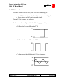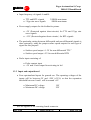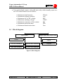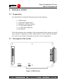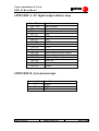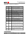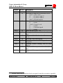
1
FAGOR AUTOMATION
FEEDBACK DISPLAY PC BOARD
Fagor Automation S. Coop.
Barrio San Andrés, s/n.
20500 - Mondragón
Tel.: (34) 43 79 95 11
Fax: (34) 43 79 17 12
Internet: www.fagorautomation.mcc.es
E-mail: [email protected]
© Copyright 1997 Ref. 9706
The information contained in this manual may be subject to change due to technical modifications.
Fagor Automation S. Coop. reserves the right to modify the contents of this manual without
prior notice.
Fagor is a registered trademark of the Fagor S. Coop.
Windows, MS-DOS, Visual C++ and Visual Basic are registered trademarks of Microsoft
Corp.
Other names of products are registered trademarks of their respective holders.
Fagor Automation S. Coop.
DRO PC BoardBoard
Contents
Page
1. GENERAL INFORMATION ........................................................................... 1
1.1 Introduction ............................................................................................. 1
1.2 Computer requirements ........................................................................... 1
1.3 Specification of the boards...................................................................... 1
1.3.1 General characteristics ................................................................. 1
1.3.2 DRO board ................................................................................... 2
1.3.3 Input and output board ................................................................. 3
1.4 Block diagram ......................................................................................... 4
2. INSTALLATION .............................................................................................. 5
2.1 Preparation .............................................................................................. 5
2.2 Description of the boards ........................................................................ 5
2.3 Setting the counting board ...................................................................... 7
2.3.1 Selecting the access address ........................................................ 7
2.3.2 Selection of the interrupt number ................................................ 7
2.4 Fitting the boards..................................................................................... 8
2.5 Copying the libraries and example programs ......................................... 9
2.6 Description of the connectors................................................................ 12
2.6.1 Feedback and probe connector................................................... 12
2.6.2 Digital input and output connector ............................................ 13
3. CONNECTION OF FEEDBACK DEVICES................................................. 14
3.1 Connection to Fagor feedback devices ................................................. 14
3.2 Connection to other feedback devices .................................................. 15
4. CONNECTING THE TOUCH PROBE.......................................................... 16
4.1 Connection of the contact-through-the-part probe................................ 16
4.2 Connection of an internal contact probe ............................................... 16
5. CONNECTION OF DIGITAL INPUTS AND OUTPUTS ............................ 18
6. FUNCTIONS IN FAGORDRO.LIB............................................................... 20
6.1 Data structures used .............................................................................. 20
6.2 Functions supplied................................................................................. 23
7. BUILDING AN APPLICATION.................................................................... 28
7.1 Programming in C language.................................................................. 28
7.2 Program example................................................................................... 28
-i-
Fagor Automation S. Coop.
DRO PC BoardBoard
Appendices
Page
APPENDIX A, PC input/output address map..................................................... 30
APPENDIX B, System interrupts ....................................................................... 30
APPENDIX C, Internal access addresses ........................................................... 31
Figures
Page
Figure 1, Block diagram........................................................................................ 4
Figure 2, DRO board ............................................................................................. 5
Figure 3, Digital input and output board ............................................................... 6
Figure 4, Feedback Connector............................................................................. 12
Figure 5, Digital input and output connector ...................................................... 13
Figure 6, Simple connection of the probe ........................................................... 16
Figure 7, Connection with a normally open contact ........................................... 16
Figure 8, Connection with a normally closed contact......................................... 17
Figure 9, Diagram of digital inputs ..................................................................... 18
Figure 10, Diagram of digital outputs ................................................................. 18
Figure 11, Connection of Digital outputs............................................................ 19
- ii -
Fagor Automation S. Coop.
DRO PC BoardBoard
1. GENERAL INFORMATION
1.1 Introduction
The Fagor DRO board is used for connecting a compatible PC with up to
four position feedback devices and a touch probe. It also has four digital
input signals and a further four output signals for carrying out automation
processes.
The software supplied will furthermore enable you to make full use of all
your board’s functions in your own particular application.
1.2 Computer requirements
•
•
•
•
At least 640KB memory
DOS version 3.0 or later
2 x 8 or 16 bit ISA slots free
Sufficient current in the PC power supply ( +5V ~ 1A, +12V ~ 1A, -12V
~ 0mA)
• C compiler
1.3 Specification of the boards
1.3.1 General characteristics
•
•
•
•
•
Operating temperature :
Storage temperature :
Relative humidity :
Weight :
Current consumption :
Ref. 9706
0ºC ÷ +45º C
-25º ÷ 70º C
20% ÷ 80%
250 g.
+5V, 50mA typical, 1A maximum
+12V, 50mA typical, 1A maximum
-12V, 0mA maximum
Date : 03/07/97
Page 1 of 32
Fagor Automation S. Coop.
DRO PC BoardBoard
1.3.2 DRO board
• Feedback inputs for four axes, with each axis consisting of:
• A and B feedback signals, plus their complemented signals.
• Home signal and its complemented signal.
• Internal 32-bit counter for each axis.
• Each axis can be configured for the following types of signals
• Differential or non-differential TTL
5V
0V
• Differential or non-differential HTL
12V
0V
• Voltage modulated differential 1Vpp Sinewave
5V
2.5V
0V
Page 2 of 32
Date : 03/07/97
Ref. 9706
Fagor Automation S. Coop.
DRO PC BoardBoard
• Input frequency of signals A and B :
• TTL and HTL signals
• 1Vpp sine wave signals
250KHz maximum
50KHz maximum
• Power supply outputs for the feedback systems.
• +5V (Protected against short-circuits) for TTL and 1Vpp sine
wave signals
• +12V (Protected against short-circuits ) for HTL signals
• The particular setting between differential and non-differential signals is
done externally, using the proper surface speed outputs for each type of
signal for this purpose:
• Surface speed output +1.5V for non-differential TTL(1)
• Surface speed output +5V for non-differential HTL
• Probe input consisting of:
• Probe contact input
• +5V and 15mA output for activating its led
1.3.3 Input and output board
• Four optoinsulated inputs for general use. The operating voltages of the
inputs will be between 0V and +24V (±25%) so that the separation
threshold between 0 and 1 will be around +6V.
• Minimum DC voltage
• Maximum DC voltage
(1)
18V
30V
See the signals of the counting board connector
Ref. 9706
Date : 03/07/97
Page 3 of 32
Fagor Automation S. Coop.
DRO PC BoardBoard
• Four optoisolated outputs with solid state relay with normally open contact. The main features are as follows:
•
•
•
•
•
•
•
Maximum load intensity
Maximum leakage intensity
Maximum AC or DC voltage
Minimum isolating voltage
Maximum resistance of the contact
Maximum activation time
Maximum deactivation time
225mA
1µA
40V
1500V
5
3ms
3ms
1.4 Block diagram
DRO Card
Digital input and output card
Probe
Inputs
First axis feedback
Second axis feedback
Third axis feedback
Fourth axis feedback
Outputs
Figure 1, Block diagram
Page 4 of 32
Date : 03/07/97
Ref. 9706
Fagor Automation S. Coop.
DRO PC BoardBoard
2. INSTALLATION
2.1 Preparation
You should have found the following items in the package:
•
•
•
•
•
•
1 DRO board
1 input and output board
2 diskettes with the software
1 37-pin male connector
1 15-pin male connector
this manual
Check the quantity and condition of the components before going on, and if
any of these is missing or in bad condition get in touch with your distributor or the closest Fagor Automation customer service department.
W8
W7
W6
W4
W3
W2
W1
W5
2.2 Description of the boards
Figure 2, DRO board
Ref. 9706
Date : 03/07/97
Page 5 of 32
Fagor Automation S. Coop.
DRO PC BoardBoard
Components of interest, numbered from left to right:
a) Expansion connector for the digital input and output connector
b) Jumpers for selecting the board address.
c) Jumpers for selecting the interruptions used by the board
d) External connector for connecting the feedback devices and the probe
Figure 3, Digital input and output board
Components of interest, numbered from left to right
a) Connector for joining to the DRO board
b) External connector for connecting the digital inputs and outputs
Note.- This board uses an ISA slot, even though its connector is not used,
since the signals are sent to it from the DRO board.
Page 6 of 32
Date : 03/07/97
Ref. 9706
Fagor Automation S. Coop.
DRO PC BoardBoard
2.3 Setting the counting board
2.3.1 Selecting the access address
The program needs to know the address where the board is located, to
be able to access the counters and other resources supplied.
The board can be configured in any address within a range of from
100 to 3E0 hexadecimal. It is first necessary to know which addresses
are not occupied by the system or by other boards. To do this, see
‘APPENDIX A, PC input/output address map’ and the configurations
of the boards that you already have fitted in the computer.
W4
W3
W2
W1
W5
For selecting the address, the board has five jumpers, W1 to W5,
which when not jumpered (without the metal hood) mean the following :
W1
W2
W3
W4
W5
20 Hex
40 Hex
80 Hex
100 Hex
200 Hex
W4
W3
W2
W1
W5
The default configuration is address 300 Hex :
2.3.2 Selection of the interrupt number
To handle the references (markers) of the feedback devices and carry
out treatment of the probe one has to work in real time and to do this,
interrupts have to be used.
Ref. 9706
Date : 03/07/97
Page 7 of 32
Fagor Automation S. Coop.
DRO PC BoardBoard
The board can work with one of three possible interrupt levels. You
have to choose one that is not being used by the system or by another
board, or even so, one which is not being used within the same application used by the DRO board. Bear in mind that if you are not in the
feedback device reference search mode or operating with the probe,
the interrupt is not being used by the program. For this purpose see
‘APPENDIX B, System interrupts’.
W8
W7
W6
To select the interrupt you are going to use there are three jumpers,
W6 to W8: jumpering one of these means the following:
W6
W7
W8
IRQ 7
IRQ 5
IRQ 3
W8
W7
W6
The default selection is interrupt IRQ 7 :
2.4 Fitting the boards
WARNING!
Switch off the PC before fitting or removing the boards, and before connecting or disconnecting the feedback and input output cables.
1. Switch off the computer, and any peripherals connected to it (printers,
monitors, etc.).
2. Remove the cover of the computer’s central processing unit (See the
computer users’ manual if required).
3. Touch the computer ground screw or put on an anti-static bracelet connected to ground.
Page 8 of 32
Date : 03/07/97
Ref. 9706
Fagor Automation S. Coop.
DRO PC BoardBoard
4. Locate the expansion slots, at the back of unit, and choose two consecutive free ISA slots. If there are none, make some space by changing the
position of other boards.
5. Loosen the screws from the expansion slot covers and take out the metal
plates (keep the screws, which will be needed later on).
6. Hold the DRO board by the top, taking care not to touch the components.
Align the board retainer plate with the window of the expansion slot.
Align the part of the board that sticks out (with gold lines) with the connector of the base. Press the board firmly onto the connector until it is
securely fitted.
7. Do the same thing with the input and output board, bearing in mind that
this is not connected to the base.
8. Fit and tighten the screws in the hole over the retainer plates.
9. Fit the cover on the unit. Connect the cables for feedback and digital signals (this can be done later). Lastly switch on the computer.
The installation of the boards is now complete, so go on to install the programs.
2.5 Copying the libraries and example programs
The programs included with the DRO board are:
• fdrodos.lib, library with the initialization functions and access to
the boards for DOS applications.
• fdrow16.dll, dynamic library for 16-bit Windows applications.
• Demo programs for building an application with the board.
We recommend making a backup copy of the diskettes supplied, for example with the MS-DOS DISKCOPY utility (See MS-DOS users’ manual for
the operations needed).
To copy the programs only for DOS applications onto your hard disk, type,
from the command line of MS-DOS :
Ref. 9706
Date : 03/07/97
Page 9 of 32
Fagor Automation S. Coop.
DRO PC BoardBoard
<diskette drive>:\INSTALL <target drive>:
Where :
<diskette drive> is the drive where the diskette is placed (A or
B)
<target drive> is your hard disk drive (C to Z)
After completing the installation of files and programs, these will be found
in directory FAGORDRO.
To copy the programs required for generating DOS and Windows 3x applications, select ‘File -> Execute’ from the Program or File Manager in Windows, and type :
<diskette drive>:\SETUP
Then follow the instructions given in the program.
Within the installation directory, apart from the program
FDEMOW16.EXE, as a demo in Windows, the directories DOS and Win16
are created, containing the files stated above.
For the demo application to operate, the following files and programs will
also be copied if this is necessary and there is no later version of the same.
In the application directory:
FDROW16.INI
MESSAGES.TXT
MSG_ENG.TXT
MSG_ESP.TXT
MSG_XXX.TXT
board configuration data
text messages for the application software
text messages in English language
text messages in Spanish language
text messages in different languages
In the Windows\System directory:
FDROW16.DLL
extension of the application for handling the
board
VSHARE.386
STKIT416.DLL
VB40016.DLL
OC25.DLL
Page 10 of 32
Date : 03/07/97
Ref. 9706
Fagor Automation S. Coop.
DRO PC BoardBoard
OC25ESP.DLL
OLE2.DLL
TYPELIB.DLL
OLE2DISP.DLL
OLE2PROX.DLL
OLE2CONV.DLL
STORAGE.DLL
COMPOBJ.DLL
OLE2.REG
OLE2NLS.DLL
STDOLE.TLB
SCP.DLL
VAEN21.OLB
CTL3DV2.DLL
VB4ES16.DLL
TABCTL16.OCX
THREED16.OCX
ANIBTN16.OCX
COMDLG16.OCX
Ref. 9706
components of Windows and Visual Basic
required for the demo program.
Date : 03/07/97
Page 11 of 32
Fagor Automation S. Coop.
DRO PC BoardBoard
2.6 Description of the connectors
2.6.1 Feedback and probe connector
Female SUBD type connector with 37 pins, and the following signal
allocation:
1
19
20
37
Pin
1
2
3
4
5
6
7
8
9
10
11
12
13
14
15
16
17
18
19
Signal
Signal A from axis 1
Signal B from axis 1
Home from axis 1
Signal A from axis 2
Signal B from axis 2
Home from axis 2
Signal A from axis 3
Signal B from axis 3
Home from axis 3
Signal A from axis 4
Signal B from axis 4
Home from axis 4
HTL 1/0 threshold
Probe (Pulse)
Probe led anode
+5V
+5V
+12V
+12V
Pin
20
21
22
23
24
25
26
27
28
29
30
31
32
33
34
35
36
37
Signal
Signal /A from axis 1
Signal /B from axis 1
Home from axis 1
Signal /A from axis 2
Signal /B from axis 2
Home from axis 2
Signal /A from axis 3
Signal /B from axis 3
Home from axis 3
Signal /A from axis 4
Signal /B from axis 4
Home from axis 4
TTL 1/0 threshold
Probe (GND)
Probe led cathode
GND (0V)
GND (0V)
Chassis (ground)
Figure 4, Feedback Connector
Page 12 of 32
Date : 03/07/97
Ref. 9706
Fagor Automation S. Coop.
DRO PC BoardBoard
2.6.2 Digital input and output connector
Female SUBD type connector with 15 pins, with the following signal
allocations:
1
9
8
15
Pin
1
2
3
4
5
6
7
8
Signal
Output 1
Output 2
Output 3
Output 4
Input 1
Input 2
Input 3
Input 4
Pin
9
10
11
12
13
14
15
Signal
Output voltage 1
Output voltage 2
Output voltage 3
Output voltage 4
GND inputs 24V
Not connected
Not connected
Figure 5, Digital input and output connector
Ref. 9706
Date : 03/07/97
Page 13 of 32
Fagor Automation S. Coop.
DRO PC BoardBoard
3. CONNECTION OF FEEDBACK DEVICES
The cables to be used must be shielded, with the mesh connected to the protection chassis at both ends (connectors). If they are to undergo sharp movements,
or be pulled or exposed to dirt or aggressive liquids they should be surrounded
by a protective sheath. If possible, use cables and extensions supplied by the
manufacturer.
3.1 Connection to Fagor feedback devices
MT and CT type scales
• Non-differential TTL signals. Supply with +5V,
connect the signals to their equivalents and connect the pins of the differential signals, on the
connector of the DRO board, to its pin 32. Io
every 50 mm (Type 0).
MX, CX and FT type scales
• Differential TTL signals. Supply with +5V, connect the signals to their equivalents. Io every 50
mm (Type 0).
MP, CP and FP type scales
• Differential 1Vpp signals. Supply with +5V, connect the signals to their equivalents. Io every 50
mm (Type 0).
MO?, CO? Type scales
• Coded Io, fixed every 20 mm (Type 1)
FO? Type scales:
• Coded Io, fixed every 100 mm (Type 3)
Page 14 of 32
Date : 03/07/97
Ref. 9706
Fagor Automation S. Coop.
DRO PC BoardBoard
3.2 Connection to other feedback devices
Bear in mind the connection recommendations of the feedback device
manufacturer.
In the event of the feedback device not supplying differential feedback signals, the corresponding pins on the DRO board connector must be connected to pin 13 or 32, depending on the signal level.
Ref. 9706
Date : 03/07/97
Page 15 of 32
Fagor Automation S. Coop.
DRO PC BoardBoard
4. CONNECTING THE TOUCH PROBE
The Fagor DRO PC board is provided with a relay contact input for 5V probes.
Depending on the type of connection applied one has to indicate, in the initialization structure of the DRO board, if the probe operates with signal logic high or
low.
4.1 Connection of the contact-through-the-part probe
Simple connection, PAM-10 type Renishaw probe:
Pin 14
Pin 15
Pin 34
Part to be measured
(electrically conductive)
Pin 33
Figure 6, Simple connection of the probe
With this type of connection operation is with low logic.
4.2 Connection of an internal contact probe
Probe with normally open contact output:
Pin 14
Pin 33
Pin 34
Pin 15
Figure 7, Connection with a normally open contact
With this type of connection, operation is with low logic.
Page 16 of 32
Date : 03/07/97
Ref. 9706
Fagor Automation S. Coop.
DRO PC BoardBoard
Probe with a ‘normally closed’ contact output:
Pin 14
Pin 33
Pin 34
Pin 15
Figure 8, Connection with a normally closed contact
With this type of connection, operation is with logic high.
Ref. 9706
Date : 03/07/97
Page 17 of 32
Fagor Automation S. Coop.
DRO PC BoardBoard
5. CONNECTION OF DIGITAL INPUTS AND
OUTPUTS
Use the SUBD 15-pin connector supplied for connecting the inputs and outputs
to the electrical cabinet. Use a shielded cable, with wires of at least a 0.14 mm 2
section, depending on the current to run through them.
The input diagram is as follows:
INPUT 1
INPUT 2
INPUT 3
INPUT 4
COME24
Figure 9, Diagram of digital inputs
The diagram of each output is :
OUTPUT
COMS
Figure 10, Diagram of digital outputs
Page 18 of 32
Date : 03/07/97
Ref. 9706
Fagor Automation S. Coop.
DRO PC BoardBoard
For each output, the following anti-interference circuit should be externally connected:
DC
LOAD
− DC +
Diode
VBR = 2 to 4 times VDC
IF = IL maximum
(1N4000 series)
LOAD
AC / DC
AC/DC
LOAD
LOAD
Resistor
R ≈ RLOAD 1W
Capacitor
0.1…1 µF 250V
AC / DC
LOAD
Figure 11, Connection of Digital outputs
Ref. 9706
Date : 03/07/97
Page 19 of 32
Fagor Automation S. Coop.
DRO PC BoardBoard
6. SUPPLIED FUNCTIONS
6.1 Data structures used
The following data structures are defined in file ‘fdrodos.h’ for applications in DOS and ‘fdrow16.h’ for Windows 3.x applications.
• Setting data for each axis :
typedef struct
{
double
BOOLEAN
unsigned int
unsigned int
unsigned int
double
unsigned int
} AxisConfig_t;
where
Resolution;
CountDirection;
TTLWaveMultiply;
SignalType;
SineWaveMultiply;
MachineErrorComp;
I0Type;
Resolution contains the axis resolution. The value can be in
any units, millimeters or inches, or even values for rotary
axes. The count function is only used for returning a significant value to the probe treatment functions.
CountDirection can be 0 or 1. A zero value indicates assuming counting with the default sign. A value of one indicates changing the count sign.
TTLWaveMultiply indicates the multiplication factor that
should be applied to the counting. A zero value means a x4
multiplication (default value), one x2, two x1, and so on.
SignalType indicates the type of signal supplied by the
feedback device. For TTL and HTL signals one has to put a
value of zero, and a value of one for 1Vpp signals.
Page 20 of 32
Date : 03/07/97
Ref. 9706
Fagor Automation S. Coop.
DRO PC BoardBoard
SineWaveMultiply indicates the value of the subdivision to
be applied in the case of 1Vpp sine wave signals. Values
between 1 and 255 are accepted. It also has to contain the
externally applied multiplication, when the signal is TTL
and the type of home marker pulse (I0) is coded. For TTL
signals with no coded I0 a value of one should be set.
MachineErrorComp indicates the value, in the same units as
the resolution, for the table sag compensation. This value is
used as follows:
counting = counting * (1 + MachineErrorComp)
for example, if one wishes to compensate for a table sag error of 10 µm per meter a value of ‘0.01 / 1000’, that is,
0.00001 has to be entered. If the compensation required is
one ten thousandth of an inch per foot, and the axis has
resolution in inches, ‘0.0001 / 12’, that is 0.000008333 has
to be entered.
I0Type indicates the type of reference mark (marker) of the
feedback device. A value of zero indicates that there are no
I0s or that these are normal, and applies both to linear and
rotary feedback devices. The following values are applied
when the feedback device is linear with coded I0s :
Value
1
2
3
4
Meaning
Distance of 20 mm and increasing
Distance of 20 mm and decreasing
Distance of 100 mm and increasing
Distance of 100 mm and decreasing
• Counting data and input values. It is also where the value for the outputs
is placed:
Ref. 9706
Date : 03/07/97
Page 21 of 32
Fagor Automation S. Coop.
DRO PC BoardBoard
typedef struct
{
unsigned int
unsigned int
double
} BoardValues_t;
InputsValue;
OutputsValue;
AxisDisplayValue[4];
InputsValue contains the value of the digital inputs, as read
in the last call to the function ReadAll Counters.
OutputsValue contains the value of the digital outputs, as
written in the last call to the function ReadAllCounters.
AxisDisplayValue contains the value of the count for the
four axes, as read in the last call to function ReadAllCounters. This value is not the number of pulses, but already has the resolution applied, as well as the direction,
multiplication and table sag error compensation for the axis
and indicated in the data structure AxisConfig_t.
• Board configuration data (only applicable under Windows) :
typedef struct
{
unsigned int PtrBoardBase;
unsigned int I0IrqNumber;
unsigned int ISA_Tic;
unsigned int NumberOfAxes;
unsigned char dummy[12];
} BoardConfig_t;
PtrBoardBase contains the board access address.
I0IrqNumber contains the interrupt number used for seeking
the references of the feedback device (I0s) and probing
points.
ISA_Tic not used, should be zero.
NumberOfAxes contains the number of axes to be handled.
Page 22 of 32
Date : 03/07/97
Ref. 9706
Fagor Automation S. Coop.
DRO PC BoardBoard
dummy not used, can have any value.
6.2 Functions supplied
IniBoard
#include “fdrodos.h”
BOOL __far __pascal IniBoard(unsigned int axesnum, AxisConfig_t __far
axiscfg[]);
or
#include “fdrow16.h”
BOOL __far __pascal IniBoard(BoardConfig_t *boardx, AxisConfig_t
__far axiscfg[]);
Initializes the board and the internal counters according to the data for each
axis. This function has to be executed before any other and only has to be
called up once in each session. It returns ‘FALSE’ if it was not possible to
initialize the board or ‘TRUE’ if the operation was correct.
An example :
We have two axes: the first is a 20µm pitch feedback device with
TTL signal, the second is a 100µm pitch feedback device with 1Vpp
signal in which we require a resolution of 5 µm. The values to be
entered are :
axiscfg[0].Resolution =
axiscfg[1].Resolution = 0.005;
/* both 5 µm */
axiscfg[0].CountDirection =
axiscfg[1].CountDirection = 0;
axiscfg[0].TTLWaveMultiply =
axiscfg[1].TTLWaveMultiply = 0; /* x4 */
axiscfg[0].SineWaveMultiply = 1;
axiscfg[1].SineWaveMultiply = 5;
/* TTL signal*/
/* x5 */
axiscfg[0].MachineErrorComp =
axiscfg[1].MachineErrorComp = 0;
axiscfg[0].I0Type = 0;
Ref. 9706
Date : 03/07/97
Page 23 of 32
Fagor Automation S. Coop.
DRO PC BoardBoard
axiscfg[1].I0Type = 3;
if(IniBoard(2, axiscfg) == FALSE)
initialization_error();
ReadBoardId
#include “fdrodos.h” or #include “fdrow16.h”
BOOL __far __pascal ReadBoardId(char __far *id_ptr);
Each DRO board has a unique identification code. This function is supplied
to read said code, which can be used as protection for the application or
simply to check the existence of the DRO board. The stream ‘id_ptr’
should have a minimum length of 17 characters, as the function leaves 16
plus the end of stream character. The function sends back ‘TRUE’ if the
reading was correct or ‘FALSE’ if it could not be read.
For example :
char idplaca[17];
if(ReadBoardId(idplaca) == FALSE)
identificator_error();
ReadAllCounters
#include “fdrodos.h” or #include “fdrow16.h”
void __far __pascal ReadAllCounters(BoardValues_t __far *ptvalue);
This function reads the counters of all the active axes, carries out the resolution, direction and table sag compensation calculations to send back the
position of the axis in the units configured. It also reads the value of the
digital inputs and updates that of the outputs. This function should be
called up every time one wishes to find out the real position of the axes.
The most usual process is to call this up from a periodic interruption. Furthermore, if the probe mode is active, it checks if this is in contact with the
part or not, by controlling the probe led coming on and going off.
Page 24 of 32
Date : 03/07/97
Ref. 9706
Fagor Automation S. Coop.
DRO PC BoardBoard
LookForI0
#include “fdrodos.h” or #include “fdrow16.h”
BOOL __far __pascal LookForI0(unsigned int axis);
After switching on the PC, the value of the counters is unpredictable. If you
wish to recover the value of the axis position, a feedback device reference
(home) search has to be made. This function activates the interrupt mode to
detect the reference mark of the selected axis.
IfI0Found
#include “fdrodos.h” or #include “fdrow16.h”
BOOL __far __pascal IfI0Found(void);
This function is used to find out if the reference mark in the selected axis
has been found by the previous function. It sends back ‘TRUE’ if the reference mark has already been overshot or ‘FALSE’ if this has not yet been
reached.
EndLookForI0
#include “fdrodos.h” or #include “fdrow16.h”
void __far __pascal EndLookForI0(void);
Whether the feedback device reference point has been found or the search
is to be canceled, this function has to be called up. This deactivates the interrupt mode and restores the normal counting mode.
Ref. 9706
Date : 03/07/97
Page 25 of 32
Fagor Automation S. Coop.
DRO PC BoardBoard
StartProbeMode
#include “fdrodos.h” or #include “fdrow16.h”
BOOL __far __pascal StartProbeMode(int mode);
To carry out probing functions with a edge probe one should first activate
this function. It carries out the preparation of the points capture zone and
the entry in interrupt mode for probing. Parameter mode has the following
meaning.
Value
0
1
Meaning
Probe activation logic low (down
flank).
Probe activation logic high (up flank).
GetProbePoint
#include “fdrodos.h” or #include “fdrow16.h”
int __far __pascal GetProbePoint(BoardValues_t __far *ptvalue);
Reads the position of the axes, as well as the status of inputs, at the time a
probe pulse is activated. Uses the same type of data as the function
ReadAllCounters, although the value of the outputs is not used.
It also checks if the probe is in contact with the part or not, by controlling
when its led comes on or goes off. It sends back :
Value
0
1
2
-1
Page 26 of 32
Meaning
There are no probing points, the position
is not significant.
This is the last point.
There are further probing points not read.
There was an overflow of the storage
zone or some other error during probing the position is not significant. .
Date : 03/07/97
Ref. 9706
Fagor Automation S. Coop.
DRO PC BoardBoard
LedProbe
#include “fdrodos.h” or #include “fdrow16.h”
int __far __pascal LedProbe(int mode)
Checks or changes the status of the probe led according to the value of parameter mode, sends back the current status of the led. The values that can
be assumed by the parameter and the return are::
Value
0
1
-1
Meaning
Only the parameter, to find out what the
status of the led is.
Led on.
Led off.
EndProbeMode
#include “fdrodos.h” or #include “fdrow16.h”
void __far __pascal EndProbeMode(void);
Exits the probing mode, although there may still be points to be read.
Ref. 9706
Date : 03/07/97
Page 27 of 32
Fagor Automation S. Coop.
DRO PC BoardBoard
7. BUILDING AN APPLICATION
7.1 Programming in C language
The library fdrodos.lib is generated with Microsoft C++ version 1.52 compiler, for working in MS-DOS with a 286 or later microprocessor.
The functions are defined as __pascal for maintaining compatibility with
the Windows version.
The library fdrow16.dll is generated for working in Windows versions 3.x.
Library fdrow16.lib should be used in order for error : unresolved externals
not to come up when linking the application.
7.2 Program example
DEMO.EXE
This program, including the source code in C language, carries out all the
functions for accessing the DRO board from DOS.
In the center of the screen, it displays the count for the four axes.
On the lower line, it displays the status of the inputs, the present value of
the outputs, the count units (inches or millimeters) and the board identification code.
Meaning of the keys in execution:
i
Toggles the count display, between millimeters and inches.
axis
When the letter for the name of the axis is pressed we go into
the home reference search for the feedback device of the axis
selected. To exit without carrying out the search press key c.
r
Resets the count displayed for all the axes.
p
Changes to working with probe mode. To exit this mode press
key c.
Page 28 of 32
Date : 03/07/97
Ref. 9706
Fagor Automation S. Coop.
DRO PC BoardBoard
1
2
3
4
9
0
Changes the value of the relevant output. If this is zero it
changes it to one and vice versa.
Makes all the outputs active
Makes all the outputs inactive
<esc> To exit the program.
Ref. 9706
Date : 03/07/97
Page 29 of 32
Fagor Automation S. Coop.
DRO PC BoardBoard
APPENDIX A, PC input/output address map
Address (Hex)
000 - 1FF
200
201
202-277
278-27F
280-2F7
2F8-2FF
300-377
378-37F
380-3AF
3B0-3BF
3C0-3CF
3D0-3CF
3E0-3EF
3F0-3F7
3F8-3FF
Function
Basic System
Reserved
Game port
Free
LPT2:
Free
COM2:
Free
LPT1:
Free
Monochrome display adapter
Reserved
Graphics/ Color adapter
Reserved
Diskette drive
COM1:
APPENDIX B, System interrupts
Interruption
3
5
7
Page 30 of 32
Usually
COM2:
LPT2:
LPT1:
Date : 03/07/97
Ref. 9706
Fagor Automation S. Coop.
DRO PC BoardBoard
APPENDIX C, Internal access addresses
Offset
0x00
0x01
0x02
0x03
0x04
0x05
0x06
0x07
0x08
0x09
0x0A
0x0B
0x0C
0x0D
0x10
0x18
0x00
0x01
0x02
0x03
0x04
(2)
R / W(2) Description
R
Counter for axis 1 (4 readings = 32 bits)
format bytes = HI MH ML LO
R
Status of axis 1 counter. Bit 5 = count direction (0 = positive), the rest are not significant.
R
Counter for axis 2 (4 readings = 32 bits)
R
Status of axis 2 counter
R
Counter for axis 3 (4 readings = 32 bits)
R
Status of counter for axis 3
R
Counter for axis 4 (4 readings = 32 bits)
R
Status of counter for axis 4
R
A/D converter, value of signal A
R
A/D converter, value of signal B
R
Probe level (0 / 1)
R
Identification code (8 bytes hex, series
reading)
R
Excess in conversion signal A (0 / 1)
R
Excess en conversion signal B (0 / 1)
R
Inputs of expansion board 1 (4 low bits)
R
Inputs of expansion board 2 (4 low bits)
W
Clearing of internal counters (Needs later
latching to make zeroing effective). Type a
‘1’ on the bit for the axis (43214321b).
W
Software latching of internal counters. Type
‘0xF0’ followed by ‘0x0F’ before reading
the counters of the four axes successively or
only the active bits of the axes to be read.
W
Selection of internal count multiplication.
Always ‘0xFF’. The counter does an x4,and
if less is required, do it via software.
W
Selection of the internal latch masks. Always ‘0xFF’
W
Selection of internal configuration. Always
R means reading and W writing.
Ref. 9706
Date : 03/07/97
Page 31 of 32
Fagor Automation S. Coop.
DRO PC BoardBoard
Offset
0x08
0x09
0x0A
0x0B
0x0C
0x0D
0x0E
0x0F
0x10
0x18
(3)
R / W(2) Description
‘0x0F’.
W
Selection of signal to be converted (A/D)
0 to 3 = axis 1 to 4
4
= I0s axes 1 and 3(3)
5
= I0s axes 2 and 4(3)
6 & 7 = do not convert
W
Selection of the interruption source
0
= none
1 to 4 = I0 axis 1 to 4
5
= probe
6
= external signal
7
= none
W
Probe led on or off (1 / 0)
W
Writing to be able to read the identification
code
W
Selection of the flank or level for interrupt
(0 / 1)
W
Resetting of the interruption
W
Generation of counter latching with no interruption
W
Resetting counter latching with no interruption
W
Outputs of the expansion board 1 (4 low
bits)
W
Outputs of the expansion board 2 (4 low
bits)
Analog values will read the first I0 as signal A and the second as signal B.
Page 32 of 31
Date : 03/07/97
Ref. 9706