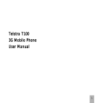
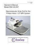
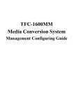
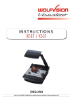
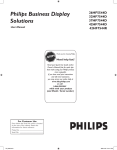
1
micro ScoutCam™ DSP User Manual March 2015 micro ScoutCam DSP-IFU 1.6 Manufacturer: Medigus Ltd Building 7A Omer Industrial Park POB 3030 Omer 84965, Israel European Authorized Representative: GBM Authorized Representative Ltd The White House 2 Meadrow Godalming GU7 3HN, UK COPYRIGHT/PROPRIETARY INFORMATION COPYRIGHT/PROPRIETARY INFORMATION This micro ScoutCam™ DSP User Manual and all information and contents hereof are the exclusive proprietary and confidential property of Medigus, and may not be disclosed to any third party nor utilized for any purpose other than the facilitation of the proper use of the micro ScoutCam™ DSP video controller in strict accordance with the instructions and safety precautions contained herein. The End-User (as defined below) and any subsequent users of the micro ScoutCam™ DSP video controller may not and shall not permit, abet, or aid others to reverse engineer, decompile, disassemble, update or modify all or any part of the micro ScoutCam™ DSP video controller and may not attempt to download, update, alter, decompile, or disassemble the micro ScoutCam™ DSP video controller software. Medigus reserves all patent, copyright, and other proprietary and intellectual property rights underlying and included in the micro ScoutCam™ DSP video controller, the micro ScoutCam™ DSP video controller software, and the micro ScoutCam™ DSP User Manual, including design, manufacturing, reproduction, and sales rights thereto. Medigus hereby grants to the End-User a non-exclusive license to use the micro ScoutCam™ DSP video controller software solely for its intended use for the operation of the micro ScoutCam™ DSP video controller in accordance with the instructions in the micro ScoutCam™ DSP User Manual. Any use the micro ScoutCam™ DSP video controller software other than as set forth herein is strictly forbidden. Medigus may terminate the aforesaid non-exclusive license immediately if the End-User or any subsequent user of the micro ScoutCam™ DSP video controller fails to comply with any of the foregoing terms and conditions. The information contained herein is subject to change at any time via notification by Medigus. DISCLAIMER (A) IN NO EVENT SHALL MEDIGUS BE LIABLE TO THE END-USER OR ANY OTHER PARTY FOR: (I) ANY LOSS OF PROFIT; (II) ANY LOSS OF GOODWILL; (III) ANY LOSS OF BUSINESS OR BUSINESS OPPORTUNITY; (IV) ANY COSTS OF PROCUREMENT OF SUBSTITUTE GOODS BY ANY ENTITY; OR (V) ANY SPECIAL, CONSEQUENTIAL, INDIRECT, OR INCIDENTAL DAMAGES, IN EACH CASE HOWEVER CAUSED AND UNDER ANY THEORY OF LIABILITY, INCLUDING DUE TO A DEFECT, FAILURE, OR MALFUNCTION OF THE MICRO SCOUTCAM™ DSP VIDEO CONTROLLER, WHETHER A CLAIM FOR SUCH DAMAGE IS BASED UPON THE WARRANTY, CONTRACT, NEGLIGENCE, OR OTHERWISE, AND WHETHER OR NOT MEDIGUS HAS BEEN ADVISED OF THE POSSIBILITY OF SUCH DAMAGE. (B) TO THE MAXIMUM EXTENT PERMITTED BY APPLICABLE LAW, IN NO EVENT SHALL MEDIGUS BE LIABLE TO THE END-USER OR ANY OTHER PARTY FOR DAMAGES IN EXCESS OF THE CONSIDERATION PAID BY THE END-USER FOR THE RESPECTIVE MICRO SCOUTCAM™ DSP VIDEO CONTROLLER GIVING RISE TO SAID LIABILITY. i LIMITED WARRANTY (C) WITHOUT LIMITATION TO THE FOREGOING, MEDIGUS SHALL HAVE NO LIABILITY FOR ANY INJURY, INCLUDING PERSONAL INJURY AND PROPERTY DAMAGE, ARISING FROM OPERATION OR USE OF THE MICRO SCOUTCAM™ DSP VIDEO CONTROLLER IN ANY MANNER WHICH DOES NOT STRICTLY ADHERE TO THE INSTRUCTIONS AND SAFETY PRECAUTIONS CONTAINED HEREIN AND IN ALL SUPPLEMENTS HERETO, AND TO THE TERMS OF THE LIMITED WARRANTY SET FORTH HEREIN. (D) NO REGULATORY APPROVALS, SUCH AS FDA PREMARKET CLEARANCE OR APPROVAL OR CE MARK APPROVAL, HAVE BEEN PROCURED BY MEDIGUS WITH RESPECT TO THE MICRO SCOUTCAM™ DSP VIDEO CONTROLLER, AND MEDIGUS MAKES NO REPRESENTATION AS TO THE SUITABILITY OF THE MICRO SCOUTCAM™ DSP VIDEO CONTROLLER FOR ANY DIAGNOSTIC, THERAPEUTIC, MEDICAL, OR OTHER PURPOSE. LIMITED WARRANTY Medigus warrants the micro ScoutCam™ DSP video controller to be free from defects in materials and workmanship until the expiration of 1 (one) year following the date of delivery of the micro ScoutCam™ DSP video controller by Medigus to the entity which is the original purchaser (the “End User”) of the micro ScoutCam™ DSP video controller directly from Medigus. Medigus will either replace, repair, or issue a credit (adjusted to reflect the age of the micro ScoutCam™ DSP video controller) for a defective micro ScoutCam™ DSP video controller or any portion thereof, at Medigus's election, as the sole remedy available to the End-User for a breach of warranty. The foregoing warranty shall apply solely to the End-User and not to any subsequent owner or user of the micro ScoutCam™ DSP video controller. To qualify for this limited warranty, the following conditions must be met by End-User: (a) The micro ScoutCam™ DSP video controller must be used in accordance with its labeling and may not be altered or subjected to misuse, abuse, accident, or improper handling; (b) Medigus must be notified in writing within thirty (30) days following discovery of a defect; (c) the micro ScoutCam™ DSP video controller must be returned to Medigus within thirty (30) days of Medigus receiving notice as provided for in paragraph (b) above; (d) as determined by Medigus upon examination of the returned micro ScoutCam™ DSP video controller: (i) the micro ScoutCam™ DSP video controller was not repaired, altered, or manipulated by anyone other than Medigus or its authorized representatives; (ii) the micro ScoutCam™ DSP video controller was not operated under conditions other than normal use and in accordance with the instructions and other provisions herein; and (iii) the micro ScoutCam™ DSP video controller was not damaged due to misuse or negligence by the End-User or any other entity. THIS LIMITED WARRANTY IS IN LIEU OF ALL OTHER WARRANTIES, EXPRESSED OR IMPLIED, WHETHER STATUTORY OR OTHERWISE, INCLUDING ANY IMPLIED WARRANTY OF MERCHANTABILITY OR FITNESS FOR A PARTICULAR PURPOSE. NO WARRANTY OTHER THAN THE LIMITED WARRANTY IS EXPRESSED OR IMPLIED BY MEDIGUS. THIS LIMITED WARRANTY IS LIMITED TO ITS EXPRESS TERMS. The exclusions and limitations set out above are not intended to, and should not be construed so as to, contravene mandatory provisions of applicable law. If any part or provision of this limited warranty is held by any court of competent jurisdiction to be illegal, unenforceable, or in conflict with applicable law, the validity of the remaining provisions of the limited warranty shall not be affected. ii Table of Contents T ABLE OF C ONTENTS List of Figures ................................................................................................................v List of Tables ............................................................................................................... vi Chapter 1 About this Manual .........................................................................................1 Purpose of this Manual ..............................................................................................1 Intended Audience .....................................................................................................1 Scope of this Manual .................................................................................................1 Acronyms ...................................................................................................................2 Warnings, Cautions, and Notes ..................................................................................2 Safety Information .....................................................................................................3 Chapter 2 Overview .......................................................................................................5 Product Overview ......................................................................................................5 Key Features ..............................................................................................................6 Chapter 3 Getting Started with micro ScoutCam™ DSP ...............................................7 micro ScoutCam™ DSP User Components ...............................................................7 Setting up the micro ScoutCam™ DSP Video Controller .........................................9 Working with the micro ScoutCam™ DSP Video Controller ...................................9 Understanding the User Interface .............................................................................10 Chapter 4 Operating the micro ScoutCam™ DSP .......................................................11 Starting the micro ScoutCam™ DSP .......................................................................12 Setting the Date and Time ........................................................................................13 Setting White Balance ..............................................................................................14 Setting the Brightness and Contrast .........................................................................14 Recording a Video ...................................................................................................14 Viewing a Recorded Video ......................................................................................15 Deleting Recorded Video .........................................................................................16 Selecting a Preset Configuration ..............................................................................16 iii micro ScoutCam™ DSP User Manual Saving a Configuration as a Preset...........................................................................17 Configuring Image Quality ......................................................................................18 Configuring Image Size ...........................................................................................19 Adjusting Image Color .............................................................................................19 Adjusting Image CCM .............................................................................................20 Adjusting Image Gamma .........................................................................................21 Configuring Image Overlay Display ........................................................................22 Setting the Illumination Control...............................................................................23 Adjusting Illumination Control Manually ................................................................24 Adjusting Exposure Auto - Setting Saturation Threshold ........................................25 Adjusting Exposure Manual - Setting Exposure Time .............................................26 Software Version .....................................................................................................26 Setting White Balance ..............................................................................................27 Noise Reduction .......................................................................................................28 Restoring Factory Default Settings ..........................................................................29 Updating micro ScoutCam™ DSP Software ...........................................................30 Chapter 5 Troubleshooting ..........................................................................................33 Using the Troubleshooting Table .............................................................................33 Troubleshooting Table .............................................................................................33 Technical Support Contact Information ...................................................................34 Appendix A - micro ScoutCam™ DSP Screens and Controls .....................................34 Appendix B - Technical Specifications........................................................................37 Appendix C - Device Symbols.....................................................................................39 iv Table of Contents L IST OF F IGURES Figure 2-1: micro ScoutCam™ DSP System Overview ................................................5 Figure 3-1: micro ScoutCam™ DSP Front Panel ..........................................................7 Figure 3-2: micro ScoutCam™ DSP Back Panel...........................................................8 Figure 4-1: Welcome Screen........................................................................................12 Figure 4-2: Main Screen ..............................................................................................12 Figure 4-3: Time & Date Screen ..................................................................................13 Figure 4-4: Recording Screen ......................................................................................15 Figure 4-5: Presets Screen ...........................................................................................16 Figure 4-6: Image Screen .............................................................................................18 Figure 4-7: Image Quality ............................................................................................18 Figure 4-8: Image Size Screen .....................................................................................19 Figure 4-9: Image Color Screen ...................................................................................20 Figure 4-10: CCM Screen ............................................................................................21 Figure 4-11: Gamma Correction Screen ......................................................................22 Figure 4-12: Overlay Display Screen ...........................................................................22 Figure 4-13: Menu Screen ...........................................................................................23 Figure 4-14: Calibration Screen ...................................................................................23 Figure 4-15: Illumination Control Screen ....................................................................24 Figure 4-16: Illumination Control Screen ....................................................................25 Figure 4-17: Image Exposure Screen ...........................................................................25 Figure 4-18: Image Exposure Screen ...........................................................................26 Figure 4-19: SW Versions Screen ................................................................................27 Figure 4-20: Noise Reduction Screen ..........................................................................28 Figure 4-21: Factory Default Screen ............................................................................29 Figure 4-22: Software Update Screen ..........................................................................30 v micro ScoutCam™ DSP User Manual L IST OF T ABLES Table 1-1: Acronyms .....................................................................................................2 Table 1-2: Conventions ..................................................................................................2 Table 3-1: micro ScoutCam™ DSP Components (Front) ..............................................7 Table 3-2: micro ScoutCam™ DSP Components (Back) ..............................................8 Table 5-1: Troubleshooting..........................................................................................33 Table B-1: Technical Specifications ............................................................................37 Table C-1: Device Symbols .........................................................................................39 vi About this Manual Chapter 1 A BOUT THIS M ANUAL This chapter provides information about this manual and includes the following sections: Purpose of this Manual Intended Audience Scope of this Manual Acronyms Warnings, Cautions, and Notes Safety Information P URPOSE OF THIS M ANUAL The purpose of this manual is to provide detailed information about the Medigus micro ScoutCam™ DSP video controller. Unless indicated otherwise for a specific section, the content of this manual is relevant for the micro ScoutCam™ DSPO version of the video controller. I NTENDED A UDIENCE This manual is intended for users and supporting technicians who will use the micro ScoutCam™ DSP video controller in conjunction with supported cameras or with products in which supported cameras are incorporated. S COPE OF THIS M ANUAL This manual includes the following chapters and appendices: Chapter 1 About this Manual – Provides information about this manual including its purpose, intended audience, scope, conventions, and safety information. Chapter 2 Overview – Provides an overview of the micro ScoutCam™ DSP video controller and its features. Chapter 3 Getting Started with micro ScoutCam™ DSP – Provides information on recognizing micro ScoutCam™ DSP user components, setting up the micro ScoutCam™ DSP video controller, and the workflow to use when operating the micro ScoutCam™ DSP. 1 micro ScoutCam™ DSP User Manual Chapter 4 Operating the micro ScoutCam™ DSP – Provides detailed instructions on operating the micro ScoutCam™ DSP video controller. Chapter 5 Troubleshooting – Provides troubleshooting information. Appendix A - micro ScoutCam™ DSP Screens and Controls – Provides the structure of the screens in the micro ScoutCam™ DSP application. Appendix B - Technical Specifications – Provides technical specifications for the micro ScoutCam™ DSP video controller. Appendix C - Device Symbols – Provides an explanation for the symbols that appear on the micro ScoutCam™ DSP video controller. A CRONYMS The following table provides a list of acronyms used in this manual. T ABLE 1-1: A CRONYMS Acronym Definition CCM Color correction matrix CMOS Complementary metal–oxide–semiconductor HDMI High definition media interface W ARNINGS , C AUTIONS , AND N OTES The following table lists the conventions used in this manual for warnings, cautions, and notes. T ABLE 1-2: C ONVENTIONS Icon Definition Warning: A warning provides important information, which if not followed, may result in death or injury to personnel or patients. Caution: Note 2 A caution provides important information about a procedure, which if not followed, may result in damage to equipment. A note provides extra emphasis on important information. About this Manual S AFETY I NFORMATION Warning: To avoid the risk of electric shock, this equipment must only be connected to a mains supply with protective earth. Warning: Do not remove the cover or panel of the micro ScoutCam™ DSP video controller. Warning: The video controller remains connected to the electricity source even when it is turned off. Warning: Do not operate the unit in the presence of electromagnetic interference. Interference may be caused by electro-surgery, diathermy, magnetic resonance imaging, or other equipment. Portable and mobile RF communications equipment may affect operation of this device. This device generates internal radiofrequency energy and, if operated properly according to these instructions, will not normally cause harmful interference to other nearby devices. If this device does cause harmful interference (determined by turning this device off and on), try the following to eliminate interference: Move, reposition or relocate the affected device. Power this device from a separate power circuit. Contact Medigus technical support if interference persists. For continued compliance with electromagnetic emissions requirements, this device must only be powered by means of the mains power cable supplied, or a replacement supplied by Medigus Ltd. Warning: Other than fuse replacement, as indicated on rear of unit, the equipment has no user replaceable parts. All other maintenance activities must be carried out by Medigus Ltd or its authorized representatives. Replace fuses only with type as indicated on rear of unit. 3 micro ScoutCam™ DSP User Manual Warning: Before use, visually check the equipment for exterior mechanical damage and for proper function. Immediately turn off and unplug any equipment that emits smoke, sparks, strange noises, or odors. 4 Caution: Do not insert any foreign objects into slots or plugs on the micro ScoutCam™ DSP video controller. Failure to heed this caution may result in damage to the micro ScoutCam™ DSP. Caution: Turn off the video controller before unplugging a camera from the micro ScoutCam™ DSP. Failure to heed this caution may result in damage to the micro ScoutCam™ DSP and/or the camera. Caution: Clean the cabinet and panel with a soft cloth moistened with a mild detergent solution. Do not use any abrasive materials or scouring powder or solvents such as alcohol and benzene. Failure to heed this caution may result in damage to the micro ScoutCam™ DSP. Caution: Clean the touch screen with a soft cloth soaked with petroleum IPA. Do not use any other chemicals. Failure to heed this caution may result in damage to the micro ScoutCam™ DSP. Caution: Do not apply extended or excessive force to the touch screen. Failure to heed this caution may result in damage to the micro ScoutCam™ DSP. Caution: This device must only be connected to auxiliary equipment supplied by Medigus Ltd, or with equipment that has been approved for use in writing by Medigus Ltd, and in accordance with the requirements of IEC 60601-1-1. Caution: At the end of its useful life, the device must be disposed of only in accordance with local regulations for the disposal of medical electronic equipment. Overview Chapter 2 O VERVIEW This chapter provides an overview of the micro ScoutCam™ DSP video controller and includes the following sections: Product Overview Key Features P RODUCT O VERVIEW The micro ScoutCam™ DSP video controller is designed for use with Medigus endoscopic cameras to provide high quality video output. It can be used with standard monitors and does not require a proprietary monitor for viewing camera output. The image captured by the camera is transmitted to the micro ScoutCam™ DSP. The image is processed in the micro ScoutCam™ DSP and output to one or more video monitors, and optionally to external media for recording and storage. The following figure shows the micro ScoutCam™ DSP connected to an endoscopic camera and a monitor. F IGURE 2-1: MICRO S COUT C AM ™ DSP S YSTEM O VERVIEW 5 micro ScoutCam™ DSP User Manual K EY F EATURES The following are some of the key features of the micro ScoutCam™ DSP video controller: 6 Sophisticated digital image processing to ensure the best image quality from Medigus cameras. Simple and intuitive operation of the micro ScoutCam™ DSP enables the user to configure many of the video parameters to meet his needs. HDMI video output. Recording and storage capability to external media. Remote software upgrades to enable easy implementation of future image processing algorithms and other features. Getting Started with micro ScoutCam™ DSP Chapter 3 G ETTING S TARTED WITH MICRO S COUT C AM ™ DSP This chapter provides information on getting started with the micro ScoutCam™ DSP video controller and includes the following sections: micro ScoutCam™ DSP User Components Setting up the micro ScoutCam™ DSP Video Controller Working with the micro ScoutCam™ DSP Video Controller MICRO S COUT C AM ™ DSP U SER C OMPONENTS The micro ScoutCam™ DSP video controller user components are all located on the front and back panels of the micro ScoutCam™ DSP. The following figure shows the front panel with its parts labeled. F IGURE 3-1: MICRO S COUT C AM ™ DSP F RONT P ANEL The following table provides a list of the components on the front panel of the micro ScoutCam™ DSP with a short description of each component. T ABLE 3-1: MICRO S COUT C AM ™ DSP C OMPONENTS (F RONT ) Component Description Power switch Used to turn the micro ScoutCam™ DSP on and off. USB port For future use. SD card slot For future use. Camera outlet For connecting a supported camera to the micro ScoutCam™ DSP. 7 micro ScoutCam™ DSP User Manual Component Description Touch screen For navigating through the micro ScoutCam™ DSP user interface to configure the micro ScoutCam™ DSP and view and record images. The following figure shows the back panel with its parts labeled. F IGURE 3-2: MICRO S COUT C AM ™ DSP B ACK P ANEL The following table provides a list of the components on the back panel of the micro ScoutCam™ DSP with a short description of each component. T ABLE 3-2: 8 MICRO S COUT C AM ™ DSP C OMPONENTS (B ACK ) Component Description Power outlet For connecting the micro ScoutCam™ DSP power cable. Equipotential terminal For ground bonding. RCA audio and video outlets For future use. Microphone jack For future use. Speaker jack For future use. PC D-Sub outlet For future use. HDMI 1, HDMI 2 For connecting HDMI micro ScoutCam™ DSP. Mini-USB outlet For technician use only. PC outlet (mini-USB) For future use. SD card slot For external media to which video can be saved. monitors to the Getting Started with micro ScoutCam™ DSP Component Description RJ-45 connection For technician use only. USB outlets (4) For future use. S ETTING UP THE C ONTROLLER MICRO S COUT C AM ™ DSP V IDEO To set up the micro ScoutCam™ DSP video monitor: 1. 2. 3. 4. 5. Ensure that the power switch is in the off position. Connect the power cable to the power inlet at the back of the micro ScoutCam™ DSP. Attach an HDMI monitor to one of the video monitor outlets at the back of the micro ScoutCam™ DSP. Attach a supported camera to the camera outlet at the front of the micro ScoutCam™ DSP. For information on supported cameras, refer to Appendix B - Technical Specifications. To save the video to external media, insert an SD card into the SD card slot at the back of the micro ScoutCam™ DSP. The micro ScoutCam™ DSP video controller is set up. W ORKING WITH THE V IDEO C ONTROLLER MICRO S COUT C AM ™ DSP This section provides information on the general workflow when operating the micro ScoutCam™ DSP video controller. To operate the micro ScoutCam™ DSP video controller: 1. 2. 3. 4. 5. Turn on the micro ScoutCam™ DSP video controller. For more information, refer to Starting the micro ScoutCam™ DSP. White balance the camera (recommended). For more information, refer to Setting White Balance. Start working with the camera. For more information, refer to the camera documentation. Record video (optional). For more information, refer to Recording a Video. When finished, switch off the micro ScoutCam™ DSP using the power switch on the front panel. 9 micro ScoutCam™ DSP User Manual Caution: Do not remove any cables or media from the micro ScoutCam™ DSP while the power switch is in the ON position. U NDERSTANDING THE U SER I NTERFACE The micro ScoutCam™ DSP application user interface consists of a series of screens that are displayed on the micro ScoutCam™ DSP’s touch screen. Some of the icons on the screen are used for navigation. Other icons are used to select options and operate the micro ScoutCam™ DSP. The following standard icons appear on almost all of the screens: – Press the home icon to return to the main menu in the application. – Press the up arrow to navigate up one level in the application. For more information on the structure of the screens in the micro ScoutCam™ DSP application, refer to Appendix A - micro ScoutCam™ DSP Screens and Controls . 10 Operating the micro ScoutCam™ DSP Chapter 4 O PERATING THE MICRO S COUT C AM ™ DSP This chapter provides detailed instructions on how to operate micro ScoutCam™ DSP video controller and includes the following sections: the Starting the micro ScoutCam™ DSP Setting the Date and Time Setting White Balance Setting the Brightness and Contrast Recording a Video Viewing a Recorded Video Deleting Recorded Video Selecting a Preset Configuration Saving a Configuration as a Preset Configuring Image Quality Configuring Image Size Adjusting Image Color Adjusting Image CCM Adjusting Image Gamma Configuring Image Overlay Display Setting the Illumination Control Adjusting Illumination Control Manually Adjusting Exposure Auto - Setting Saturation Threshold Adjusting Exposure Manual - Setting Exposure Time Software Version Setting White Balance Noise Reduction Restoring Factory Default Settings Updating micro ScoutCam™ DSP Software Note Calibration may only be performed by Medigus authorized technicians. 11 micro ScoutCam™ DSP User Manual S TARTING THE MICRO S COUT C AM ™ DSP To turn on the micro ScoutCam™ DSP video controller: 1. Turn the power switch to the on position. The Welcome screen appears on the touch screen. F IGURE 4-1: W ELCOME S CREEN 2. Approximately 25 seconds later, the Main Screen appears on the touch screen. F IGURE 4-2: M AIN S CREEN 3. 12 The micro ScoutCam™ DSP is ready for use. Operating the micro ScoutCam™ DSP S ETTING THE D ATE AND T IME You can configure the micro ScoutCam™ DSP video controller with the current date and time. To configure the date and time: 1. 2. 3. Press Menu in the main menu. The Menu screen (Figure 4-13) appears. Press Setup. The Settings screen appears. Press Date & Time. The Time and Date screen appears. F IGURE 4-3: T IME & D ATE S CREEN 4. 5. 6. 7. Press a date or time field. Press numbers on the keypad to set the value for the selected date or time field. Press Enter. The value is stored in the selected field. Repeat steps 4 - 6 until the date and time are configured. 13 micro ScoutCam™ DSP User Manual S ETTING W HITE B ALANCE To ensure that the color in the video is accurate, it is important to ensure that white balance is performed. To configure white balance: 1. 2. Ensure that a camera is attached to the micro ScoutCam™ DSP video controller. Press White Balance in the main menu. The micro ScoutCam™ DSP performs white balance and the “White balance in progress” message is displayed. The white balance process ends with a PASS/FAIL message. If the white balance process fails, one of the following messages appears: Too much light – Decrease the amount of light and try to set the white balance. Not enough light – Increase the amount light and try to set the white balance. S ETTING THE B RIGHTNESS AND C O NTRAST You can set the video brightness and contrast from the Main Screen. To set brightness and contrast: 1. 2. 3. 4. In the Main Screen (Figure 4-2), press the up and down arrows around the Brightness button to raise or lower the brightness of the video. To return the brightness setting to the factory default, press Brightness. Press the up and down arrows around the Contrast button to raise or lower the contrast of the video. To return the contrast setting to the factory default, press Contrast. R ECORDING A V IDEO You can record a video on the micro ScoutCam™ DSP and save it to external media. To record a video: 1. 2. 14 Press Menu in the main menu. The Menu screen (Figure 4-13) appears. Press Recording. The Recording screen appears. Operating the micro ScoutCam™ DSP F IGURE 4-4: R ECORDING S CREEN 3. Press . The micro ScoutCam™ DSP starts recording video, the word Recording appears on the video monitor, and the dot in the center of the recording icon turns red . The video is saved to the external media. Note If a stored video is being played, recording does not start when is pressed. The clip size limit is 2GB (approximately 2 hours). The SD card is not to be ejected (and inserted back) during recording or playback of video files. To stop recording, press V IEWING A . Recording stops. R ECO RDED V IDEO You can view a recorded video on the micro ScoutCam™ DSP video controller. To view a recorded video: 1. 2. 3. 4. 5. 6. Press Menu in the main menu. The Menu screen (Figure 4-13) appears. Press Recording. The Recording screen (Figure 4-4) appears. Press or . A list of video files saved to the external media appears on the monitor with the current video recording highlighted. To move to the next video recording in the list, press . To move to the previous video recording in the list, press . Press . The selected video plays on the attached monitor. 15 micro ScoutCam™ DSP User Manual Note 7. 8. Video playback does not start when recorded. is pressed when a video is being To pause the video playback, press . The video pauses. To continue playback, press again. To stop video playback, press . The video playback stops. Pressing starts playback from the beginning of the recording. D ELETING R ECORDED V IDEO You can delete recorded video files from the external media on which they are saved. To delete a video file: 1. 2. 3. 4. Press Menu in the main menu. The Menu screen (Figure 4-13) appears. Press Recording. The Recording screen (Figure 4-4) appears. Press or . A list of video files saved to the selected external media appears on the monitor, with the current video recording highlighted. Press or until the video you want to delete is highlighted. 5. Press . The selected video file is deleted from the external media. S ELECTING A P RESET C ONFIGURATION You can select a preset configuration for the micro ScoutCam™ DSP. To select a preset: 1. Press Presets in the main menu. The Presets screen appears. F IGURE 4-5: P RESETS S CREEN 16 Operating the micro ScoutCam™ DSP 2. 3. Press the up and down arrows around the Select button to cycle through the five preset configurations. When the desired preset configuration is displayed, press Select. The selected preset configuration is used. S AVING A C ONFIGURATION AS A P RESET You can save the current configuration of the micro ScoutCam™ DSP to a preset configuration. This enables you to save frequently used configurations and access them quickly. To save the current configuration to a preset: 1. 2. 3. Press Presets in the main menu. The Presets screen (Figure 4-5) appears. Press the up and down arrows around the Select button to cycle through five preset configurations. When the preset configuration you want to overwrite is displayed, press Save Current Setup. The current micro ScoutCam™ DSP configuration is saved to the selected preset. The following parameters are saved in the preset configuration: Brightness Contrast White balance parameters Gamma Illumination value CCM Spatial filter enable/disable Overlay Image Size Note You cannot overwrite the factory default preset configuration. The last setup selected is used the next time the machine is powered up. 17 micro ScoutCam™ DSP User Manual C ONFIGURING I MAGE Q UALITY You can configure the quality of the images and video. To configure image quality: 1. 2. Press Menu in the main menu. The Menu screen (Figure 4-13) appears. Press Image. The Image screen appears. F IGURE 4-6: I MAGE S CREEN 3. Press Quality. The Image Quality screen appears. F IGURE 4-7: I MAGE Q UALITY 4. 5. 18 Press the up or down arrows around the Brightness button to raise or lower the brightness of the video. To return the brightness setting to the factory default, press Brightness. Operating the micro ScoutCam™ DSP 6. 7. Press the up or down arrows around the Contrast button to raise or lower the contrast of the video. To return the contrast setting to the factory default, press Contrast. C ONFIGURING I MAGE S IZE You can configure the size of the image in the video. To configure the image size, in the main menu: 1. 2. 3. Press Menu. The Menu screen (Figure 4-13) appears. Press Image. The Image screen (Figure 4-6) appears. Press Size. The Image Size screen appears. F IGURE 4-8: I MAGE S IZE S CREEN To view the original size of the image, press Native. To view the image in medium size, press Medium. To view the image in large size, press Large. A DJUSTING I MAGE C OLO R You can adjust the red, green, and blue (RGB) values for the image. To adjust the color of the image: 1. 2. 3. Press Menu in the main menu. The Menu screen (Figure 4-13) appears. Press Image. The Image screen (Figure 4-6) appears. Press Color. The Image Color screen appears. 19 micro ScoutCam™ DSP User Manual F IGURE 4-9: I MAGE C OLOR S CREEN 4. 5. 6. 7. 8. 9. Press the up or down arrows around the R button to raise or lower the red values of the image. To return the red value setting to the factory default, press R. Press the up or down arrows around the G button to raise or lower the green values of the image. To return the green value setting to the factory default, press G. Press the up or down arrows around the B button to raise or lower the blue values of the image. To return the blue value setting to the factory default, press B. A DJUSTING I MAGE CCM You can adjust the colors by using predefined color correction matrix. To adjust the CCM of the image: 1. 2. 3. 20 Press Menu in the main menu. The Menu screen (Figure 4-13) appears. Press Image. The Image screen (Figure 4-6) appears. Press CCM. The CCM screen appears. Operating the micro ScoutCam™ DSP F IGURE 4-10: CCM S CREEN 4. Note Press the up and down arrows around the Select button to cycle through ten preset configurations. The CCM configuration displayed is applied. CCM can be influenced by the ambient illumination. Please contact Medigus for a custom CCM that is optimal for your specific application. A DJUSTING I MAGE G AMMA You can adjust the Gamma by using predefined Gamma values. To adjust the Gamma of the image: 1. 2. 3. Press Menu in the main menu. The Menu screen (Figure 4-13) appears. Press Image. The Image screen (Figure 4-6) appears. Press Gamma. The Gamma Correction screen appears. 21 micro ScoutCam™ DSP User Manual F IGURE 4-11: G AMMA C ORRECTION S CREEN 4. Press the up and down arrows around the Select button to cycle through 31 preset configurations. The Gamma correction values are applied. C ONFIGURING I MAGE O VERLAY D ISPLAY You can configure the overlay of the image in the video. To configure the image overlay: 1. 2. 3. Press Menu in the main menu. The Menu screen (Figure 4-13) appears. Press Image. The Image screen (Figure 4-6) appears. Press Overlay. The Overlay Display screen appears. F IGURE 4-12: O VERLAY D ISPLAY S CREEN 22 Operating the micro ScoutCam™ DSP To view the original image in a square format, press No Masking. To view the image using circular masking, press Circle Masking. To View the image using corners masking, press Corners Masking. S ETTING THE I LLUMINATION C ONTROL micro ScoutCam™ DSP provides means to drive auxiliary power LED for illumination (please consult Medigus for the correct connections and specifications). To set the illumination: 1. Press Menu in the main menu. The Menu screen appears. F IGURE 4-13: M ENU S CREEN 2. Press Calibration. The Calibration screen (Figure 4-14) appears. F IGURE 4-14: C ALIBRATION S CREEN 23 micro ScoutCam™ DSP User Manual 3. Press Illumination. The Illumination Control screen appears. F IGURE 4-15: I LLUMINATION C ONTROL S CREEN To set the illumination to auto adjustment according to the background illumination, press Auto. To turn off the illumination, press Off. To set the illumination value manually, press Manual. A DJUSTING I LLUMINATION C ONTROL M ANUALLY micro ScoutCam™ DSP provides means to operate an auxiliary power LED for illumination. Note Please consult Medigus for the correct connections and specifications. You can adjust the illumination of the Auxiliary LED manually. To adjust the illumination manually: 1. 2. 3. 4. 24 Press Menu in the main menu. The Menu screen (Figure 4-13) appears. Press Calibration. The Image screen (Figure 4-14) appears. Press Illumination Control. The Illumination Control screen appears. Press Manual. Operating the micro ScoutCam™ DSP F IGURE 4-16: I LLUMINATION C ONTROL S CREEN 5. Press the up and down arrows around the Set button to cycle through the 11 illumination values. The displayed illumination value is applied. A DJUSTING E XPOSURE A UTO - S ETTING S ATURATIO N T HRESHOLD micro ScoutCam™ DSP provides means to set the saturation threshold. To set the saturation threshold: 1. 2. 3. 4. Press Menu in the main menu. The Menu screen (Figure 4-13) appears. Press Calibration. The Image screen (Figure 4-14) appears. Press Exposure. The Image Exposure screen appears. Press Auto. F IGURE 4-17: I MAGE E XPOSURE S CREEN 25 micro ScoutCam™ DSP User Manual 5. Note Press the up and down arrows to set the exposure threshold. The threshold determines the upper limit value where every value above it is counted as saturation. If more than certain number pixels are above that threshold the automatic shutter will be closed. A DJUSTING E XPOSURE M ANUAL - S ETTING E XPOSURE T IME micro ScoutCam™ DSP provides means to set the exposure time. To set the exposure time: 1. 2. 3. 4. Press Menu in the main menu. The Menu screen (Figure 4-13) appears. Press Calibration. The Image screen (Figure 4-14) appears. Press Exposure. The Image Exposure screen appears. Press Manual. F IGURE 4-18: I MAGE E XPOSURE S CREEN 5. Note Press the up and down arrows to set the exposure duration 0-100% (33msec). When exposure is manual, the AGC is disabled. S OFTWARE V ERSION You can review the built-in software versions of the micro ScoutCam™ DSP. 26 Operating the micro ScoutCam™ DSP To review the software version of the micro ScoutCam™ DSP: 1. 2. 3. Press Menu in the main menu. The Menu screen (Figure 4-13) appears. Press Calibration. The Calibration screen (Figure 4-14) appears. Press About. The SW Versions screen appears. F IGURE 4-19: SW V ERSIONS S CREEN 4. Press Continue. The micro ScoutCam™ DSP system returns to the Calibration menu. S ETTING W HITE B ALANCE To ensure that the color in the video is accurate, it is important to ensure that white balance is performed. Another way of setting the WB is via the Calibration menu. To configure white balance: 1. 2. 3. 4. Press Menu in the main menu. The Menu screen (Figure 4-13) appears. Press Calibration. The Calibration screen (Figure 4-14) appears. Ensure that a camera is attached to the micro ScoutCam™ DSP video controller and pointed at a white target. Press WB. The micro ScoutCam™ DSP performs white balance and the “White balance in progress” message is displayed. 27 micro ScoutCam™ DSP User Manual N OISE R EDUCTIO N You can reduce arbitrary or spatial noise. To reduce noise: 1. 2. 3. Press Menu in the main menu. The Menu screen (Figure 4-13) appears. Press Calibration. The Image screen (Figure 4-14) appears. Press Noise Reduction. The Noise Reduction screen appears. 1 F IGURE 4-20: N OISE R EDUCTION S CREEN To set the Auto Noise filter, press Auto. When noise is detected (raises above certain threshold), micro ScoutCam™ DSP operates the RF cancelation and the spatial filters automatically. To set the noise reduction manually, press Manual. With this option the RF and spatial filter can operate by user selections. To operate the RF filter, press RF and ensure that the dot in the center of the RF icons is filled. To disable the RF filter, press RF and ensure that the dot in the center of the icon disappears. Note 28 If there is no RF noise and the filter is turned on, performance is reduced. Operating the micro ScoutCam™ DSP To operate the spatial filter, press Spatial and make sure the dot in the center of the spatial icon is filled. Note Operation of the spatial files reduces the spatial resolution. Both filters can be used simultaneously. To disable the spatial filter, press Spatial and make sure the dot in the center of the spatial icon is not filled. Note The System sub-menu is for use by authorized technicians only. R ESTORING F ACTORY D EFAULT S ETTINGS You can return the micro ScoutCam™ DSP to the factory default settings. To restore the factory default settings: 1. 2. 3. Press Menu in the main menu. The Menu screen (Figure 4-13) appears. Press Setup. The Settings screen appears. Press Factory Defaults. The Factory Default screen appears. F IGURE 4-21: F ACTORY D EFAULT S CREEN 4. Press Continue. The micro ScoutCam™ DSP system configuration is restored to the factory default settings. 29 micro ScoutCam™ DSP User Manual U PDATING MICRO S COUT C AM ™ DSP S OFTWARE You can update the software in the micro ScoutCam™ DSP video controller easily. This provides an easy way for Medigus to add functionality to the micro ScoutCam™ DSP. Software updates can be delivered on an SD card. Note SD card size must be minimum 1Gbyte and its lock must be off for the update. To update the software: 1. 2. 3. 4. Ensure that the micro ScoutCam™ DSP video controller is off. Remove the SD card from the slot in the back of the micro ScoutCam™ DSP. Insert the SD card with the software update into the SD card slot in the back of the micro ScoutCam™ DSP. Turn on the micro ScoutCam™ DSP. The Software Update screen appears. F IGURE 4-22: S OFTWARE U PDATE S CREEN 5. 6. 7. Note 30 Press Update. The display will change to update mode that includes a progress bar until the update process is completed. Once the update process is completed, the user is requested to turn off the micro ScoutCam™ DSP video controller for a few seconds. After a few seconds, the software is updated and micro ScoutCam™ DSP can be restarted. Restore the Factory Default Settings, as described in the previous section. During update, the screen will turn black for five minutes. Operating the micro ScoutCam™ DSP It takes approximately ten minutes for the software to complete updating. Once the update process is completed, the user is requested to turn off the micro ScoutCam™ DSP video controller for a few seconds. Do not turn off the micro ScoutCam™ DSP during the update process until requested to do so. The SD card is not to be ejected during the update. After restarting the system in case of a successfully update the user can eject the SD card. If you do not want to update the software, press Cancel. The main menu appears. 31 Troubleshooting Chapter 5 T ROUBLESHOOTING This chapter provides information on troubleshooting issues with micro ScoutCam™ DSP video controller and includes the following sections: the Using the Troubleshooting Table Troubleshooting Table U SING THE T ROUB LESHOOTING T ABLE To use the troubleshooting table: 1. 2. 3. Search for the issue you are experiencing in the Symptom column. Perform the remedies listed in the Remedy column in the order listed. After performing each remedy, check the micro ScoutCam™ DSP to see if the issue was resolved. T ROUBLESHOOTING T ABLE The following table provides troubleshooting instructions. T ABLE 5-1: T ROUBLESHOOTING Symptom Remedy Reset the micro ScoutCam™ DSP video controller. Check the cables connected to the micro ScoutCam™ DSP. If any of the cables are not properly attached, remove and reattach the cables. No picture is displayed on the monitor Reset the micro ScoutCam™ DSP configuration to the factory default. For more information, refer to Restoring Factory Default Settings. Troubleshoot the monitor. For information about troubleshooting the monitor, refer to the monitor manufacturer’s documentation. Contact Medigus technical support. The micro ScoutCam™ DSP user interface does not appear on the touch screen Reset the micro ScoutCam™ DSP video controller. Contact Medigus technical support. 33 micro ScoutCam™ DSP User Manual Symptom Remedy An error occurs during a software update Reset the micro ScoutCam™ DSP video controller. Contact Medigus technical support. Disconnect the micro ScoutCam™ DSP from mains. micro ScoutCam™ DSP does not operate, no image and no sound Extract the fuse cartridge micro ScoutCam™ DSP. from the back of the Replace if necessary one or both fuses. Resume the micro ScoutCam™ DSP. Contact Medigus technical support. Turn off the unit for five minutes. Temperature exceeds 50° and a continuous beep is heard Video interference, including the background which is supposed to be black During software update process both the monitor and the touch screen become black Make sure no object blocks the aeration slot of the enclosure. Resume the system. If the warning appears again, turn off the unit and contact Medigus technical support. Replace the HDMI cable. Both the monitor and the touch screen should be black during the update procedure for 5-10 minutes (depending on the software update package) If after 15 minutes the monitor and the touchscreen are still black and nothing is display please turn off the micro ScoutCam™ DSP video controller and turn it on again after 5 minutes. The micro ScoutCam™ DSP will check if the update was completed and will continue the update if necessary. A message will be displayed if recovery process was made. T ECHNICAL S UPPORT C ONTACT I NF ORMATION Medigus technical support can be contacted at: E-mail: [email protected] Telephone: +1-855-209-8703 Appendix A - MICRO S COUT C AM ™ DSP S CREENS AND C ONTROLS 34 micro ScoutCam™ DSP Screens and Controls This appendix provides the flow of the micro ScoutCam™ DSP screens and controls. Main screen White Balance Brightness Contrast Presets Select Save Current Setup Menu Image Color R G B Quality Brightness Contrast Size Native Medium Large CCM Select Gamma Gamma Overlay No Masking Circle Masking Corners Masking Setup Factory defaults Adjust time Recording Previous movie/image 35 micro ScoutCam™ DSP User Manual 36 Next movie/image Stop Play/pause Record start/stop Delete Calibration Illumination Auto Manual Off Select Illumination Control Auto Manual Off Set Exposure Auto Manual WB Noise Reduction Auto Manual RF Spatial About SW Versions Software Update Update Technical Specifications Appendix B - T ECHNICAL S PECIFICATIONS This appendix provides the technical specifications for the micro ScoutCam™ DSP video controller. T ABLE B-1: T ECHNICAL S PECIFICATIONS Specification Value Physical Specifications Height 100 mm (3.94”) Length 350 mm (13.78”) Width 290 mm (11.42”) Weight 3.6 kg (7 lbs. 15 oz.) Power Specifications Input Voltage 100V - 240V AC; 50-60 Hz Input Current ~1.0A USB Output Voltage 5V DC USB Output Current 400mA Supported Cameras Medigus 1.2mm CMOS camera Medigus LEDprobe camera Storage Specification SD card 16 Gb max. Supported SD card types SD, SDHC Display Out Specifications HDMI (2 outlets) 720P Human Interface Specifications TFT touch screen 4/3” 480 x 272 Operating Specifications 37 micro ScoutCam™ DSP User Manual Specification Value Temperature 13°C - 32°C (55°F – 90°F) Humidity 20% - 90%, non-condensing Safety Safety Classification 38 Class I; Type BF Device Symbols Appendix C - D EVICE S YMBOLS This appendix provides descriptions for the symbols that appear on the micro ScoutCam™ DSP video controller. T ABLE C-1: D EVICE S YMBOLS Symbol Description Attention: Refer to the User Manual. Equipotential terminal Date of manufacture Manufacturer Type BF (electrical safety classification) REF SN Device identification Serial number Do not dispose in garbage User replaceable fuses. Replace only with the type indicated on the back of the unit. Audio out Audio in USB port Ethernet port SD mass storage memory card slot 39