1
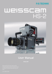
cev.fr
PRO35Digital Image Converter
User Manual
Model 2002
0
Contents
Congratulation………………………………………………………………………………… 1
Introduction……………………………………………………………………………………. 3
Attaching the PRO35Digital to your camera with Lightweight support…………………. 7
Power connection…………………………………………………………………………….. 9
Back Focus adjustment………………………………………………………………………11
Back Focus adjustment without a reliable test chart…...……………………………….. 13
2
Introduction
Delivery Content PRO35Digital
check each of your lenses, f-stop combinations and
1 – PRO35Digital image converter with an
shutter adjustments for compatibility.
Items needed before you begin: (1) a 2.5mm hex
Arri PL lens mount and B4 camera mount.
wrench, like the Xcelite 99-74mm, (2) a 35mm format
1 – Lightweight support with 15mm Rods;
film lens for testing. (3) A high quality test chart, such
short and long and a short post.
2 – Protective caps
as the Putora HDTV Sharpness Indicator chart; or for
1 – Power cable
fieldwork, the Putora 7A9 chart, and (4) a monitor.
Attaching the PRO35Digital
Munich / New York, 4 December 2002
to Your Camera
P+S Technik GmbH
Rosenheimerstrasse 139
81761 München
Germany
Tel: 49 89 4509 8230
www.pstechnik.de
Technical support: [email protected]
Avoid Murphy’s Law: Assemble and test the
PRO35Digital adapter BEFORE the first day of your
production. After attaching the unit to your camera
according to the steps outlined below, be sure to
3
Pos. Description
1
INPUT
Comment
7 Pin Fischer female
socket
Pin 1 – not connected
Pin 2 – VTR trigger
Pin 3 – Bat Pin 4 – not connected
Pin 5 – not connected
Pin 6 – Bat +
Pin 7 – RET
– view of connector
from above–
2
REMOTE
3 Pin Fisher female
socket
Pin 1 – GND
Pin 2 – N.C.
Pin 3 – VTR
–view of connector
from above–
3
RET
RET button
4
Image
Plane
Line and Tape Hook
4
Pos. Description
Comment
5
Control LED GREEN Æ
RED (low power) Æ
Blinking light Æ
6
Speed
Control
Manual
RUN
ND
Function
Back Focus
7
8
9
5
Good speed control
Acceptable speed
Below minimum
speed
Wheel
GREEN button
Adjustable “ND
Filter”
Lever
10
11
6
Bottom 3/8-inch
thread for Light
weight support
Thread for
Bridge plate
support
Follow the steps below to properly attach the PRO35Digital Image Converter to
your camera with lightweight support.
Steps
Instructions
1
Make sure that the quick-lock plate holder on
Explanatory Notes
the bottom of the camera is provided for
lightweight support.
2
Assemble the support bridge delivered with
the PRO35Digital on the quick-lock plate, as
shown in photo.
Continued on next page . . .
7
3
Assemble the PRO35Digital.
3.1
Attach the post to the bottom of the
PRO35Digital unit.
3.2
Lower the support for easier installation
(lever shown as Screw A in photo).
3.3
Loosen two screws on either side of Screw B
in photo.
3.4
Install the PRO35Digital image converter on
the camera (B4 Mount ) and lock the mount.
3.5
Raise the support to the correct height (lever
shown as Screw A in photo).
3.6
Engage and tighten the knob B in the bottom
of the post.
3.7
Tighten the two screws placed either side of
Screw B.
8
Power Connection for the PRO35Digital
To power the PRO35Digital, you need the power cable #19339, included with the unit.
The power cable is fitted with the standard Hirose 12-pin connector for the lens socket on the camera and the 7pin Fischer plug for the “Input” socket on the PRO35Digital image converter.
With this power cable, the VTR button on the video camera automatically starts the PRO35Digital unit. Control
the PRO35Digital manually with the RUN button, or by remote control via the Fisher 3-pin “Remote” socket.
9
Manual “RUN” control and VTR signal logic:
MANUAL “RUN” STATUS
OFF
ON
VTR SIGNAL
RESULT
VTR ON*
Image converter ON
VTR OFF
Image converter OFF
VTR ON*
Image converter ON
VTR OFF
Image converter ON
*During VTR = ON: The camera is in RECORD MODE and the Manual RUN Button on the PRO35Digital
unit is not active.
Other power cables are available from P+S Technik – these cables only allow the manual function of the RUN
button.
10
Back Focus Adjustment
The PRO35Digital image converter has a back focus adjustment that allows the user to match the flange focal
distance of each individual video camera. This adjustment may have to be checked during production if the
camera is subjected to significant temperature fluctuations.
The following describes the simple steps needed to adjust the image converter to the camera.
(No special tools are needed):
11
Steps
Instructions
Explanatory Notes
1
Mount a film lens needs to the Image
Select a mid range film lens; around 50mm.
converter.
2
Place a focusing chart at a reasonable
distance and set the focus of the film lens at
that distance.
2.1
Turn the image converter ON.
Open the adjustable ND FILTER to Position 0.
2.2
Close the iris of the film lens to around T4.
2.3
Unscrew the lever, marked “8” in the photo.
Turn the ring to adjust for best sharpness.
2.4
Use a good quality monitor to evaluate the
picture.
Tighten lever 8.
The Pro35Digital image converter is precisely
adjusted for the camera.
12
In the field, if a reliable test chart is not available, adjust the back focus using the
following method:
Steps
Instructions
Explanatory Notes
1
Mount a film lens to the PRO35Digital.
Select a mid range film lens (around 50mm)
2
Use a white chart.
Set a white chart at a reasonable distance to fill the image.
2.1
Turn the PRO35Digital unit OFF.
Open the adjustable “ND filter” to Position 0.
2.2
Close the iris of the film lens far enough to
allow the video camera to show the grain
pattern of the ground glass.
2.3
Unscrew lever “8” (shown labeled in photo),
and turn the ring to adjust the sharpness.
Tighten lever “8.”
2.4
When the grain pattern is sharp, the
Pro35Digital is precisely adjusted for the
camera.
13
Optional accessories for the PRO35Digital
•
Putora Sharpness Indicator Chart
•
# 19339 PRO35Digital power cable
•
# 19376 PRO35Digital lens support 19mm
Optional Lens Mounts
Panavision mount (on request).
Contact you local P+S Technik dealer for prices and availability.
14
Technical Information No. 49
October 2006
Support systems for use with the PRO35 Image Converter
This document explains the different possibilities of attaching additional accessories (like matte box and follow focus)
to a PRO35 setup. We strictly recommend using any support system when shooting with the PRO35 Image Converter
in order to stabilize your setup and simultaneous take weight of the video camera’s B4 mount, i.e. when using heavy
lenses (zoom lenses etc).
There are three possible solutions, explained in the following:
1.
15mm light weight support (by default delivered with the PRO35)
> for use with normal (prime) lenses
> for attachment of 15 mm light weight accessories
2.
15mm light weigth support (ARRI based)
3.
19mm heavy duty support – Chrosziel based
> for use with heavy lenses (i. e. zoom lenses)
> for attachment of 19mm movie accessories
4. 19mm heavy duty support – ARRI based
> for use with heavy lenses (i. e. zoom lenses)
> for attachment of 19mm accessories
Support bridges to adapt from 19mm ligth weigth support to 15mm heavy duty support are available as well:
Pos.
1
2
Artice #
19710
19715
Description
PRO35 support bridge for 19mm to 15mm rods
PRO35 support bridge for 15mm to 15mm rods
© P+S TECHNIK GmbH, Siemensstr. 12, 85521 Ottobrunn / Munich, Germany | Tel +49 (0) 89 45 09 82 30 | Fax +49 (0) 89 45 09 82 40 | [email protected]
www.pstechnik.de
Technical Information No. 49
October 2006
1.
15mm Light-weight Support for the PRO35
The 15 mm support bridge and rods are included in the delivery. A holder for the 15 mm rods is required on the
camera side. This holder is offered by both Chrosziel and ARRI and is possible to purchase directly from P+S Technik.
By default the PRO35 Image Converter is delivered with a 15mm light weight support system, including a support
bridge (3) and four 15mm rods (4) needed. It stabilizes the PRO35 setup and 15mm accessories can be attached.
IMPORTANT: In order to connect the light weight support to your video camera you need a holder plate for 15mm
rods on camera side, which is prepared for light weight support connection. This holder is possible to purchase
directly from P+S Technik.
Setup information:
Pos
Order # Description
1
2
3
4
[19004]
[19004]
5
19004
Holder Plate from ARRI or Chrosziel.
The ARRI light weight support for video cameras is based on the LWS-4.
Light weight supports for Sony, Ikegami, JVC, Hitachi, Philips, Thomson available.
Quicklock plate (has to be compatible to your base plate (1))
Support bridge (comes with the PRO35)
Four 15mm rods (come with the PRO35):
75mm (two times) for the support of the Image converter and
240mm (two times) for additional movie accessories
PRO35 Image Converter
All products can be ordered by P+S Technik in Munich or through our dealers
© P+S TECHNIK GmbH, Siemensstr. 12, 85521 Ottobrunn / Munich, Germany | Tel +49 (0) 89 45 09 82 30 | Fax +49 (0) 89 45 09 82 40 | [email protected]
www.pstechnik.de
Technical Information No. 49
October 2006
2.
Light Weight Support for the PRO35 Image Converter ( ARRI based )
The following accessories are based on the ARRI LWS-4 and ARRI light-weight adapter plates for the SONY, PANASONIC and Thomson cameras and allows you to fit additional accessories, such as follow focus, mattebox....
based on the LWS 15mm support. A special support bridge for the PRO35Digital is included in the delivery of the
Image Converter:
Pos.
1
1
2
4
6
7
Article #
19548
19547
21958
19590
16167
19591
Describtion
Sony Ligth Weigth Adapter SLB-2
Panasonic Ligth Weigth Adapter PLB-2
Ligth Weigth Support LWS-4; compete with 15mm rods (97mm and 170mm long)
Hand Grip Extension
Hand Grip with ON/OFF Switch
Hand Grip Extension
© P+S TECHNIK GmbH, Siemensstr. 12, 85521 Ottobrunn / Munich, Germany | Tel +49 (0) 89 45 09 82 30 | Fax +49 (0) 89 45 09 82 40 | [email protected]
www.pstechnik.de
Technical Information No. 49
October 2006
3.
19mm Heavy Duty Support for the PRO35 (Chrosziel based setup)
The following table and drawings describe, which articles are necessary for a Chosziel based heavy duty support
setup in order to use heavy lenses (like zoom lenses) or to connect 19mm heavy duty based accessories to your
PRO35 setup.
Pos.
1
Order #
18478
2
3
4
18477
19376
16245
16251
19545
18688
19544
Description
Bridge plate for 19mm rods for Sony and Panasonic video cameras
incl. 440m rods (Chrosziel)
Quicklock plate for Sony and Panasonic video cameras (Chrosziel)
PRO35 support bridge for 19mm rods (without rods)
Pair of spare rods for bridge plate 19mm x 650mm
Pair of spare rods for bridge plate 19mm x 440mm
Pair of spare rods for bridge plate 19mm x 440mm (carbon fibre)
Pair of spare rods for bridge plate 19mm x 240mm
Pair of spare rods for bridge plate 19mm x 240mm (carbon fibre)
All products can be ordered from P+S Technik in Munich or through our local dealers
© P+S TECHNIK GmbH, Siemensstr. 12, 85521 Ottobrunn / Munich, Germany | Tel +49 (0) 89 45 09 82 30 | Fax +49 (0) 89 45 09 82 40 | [email protected]
www.pstechnik.de
Technical Information No. 49
October 2006
4. 19mm Heavy Duty Support for the PRO35 (ARRI based setup)
The following table and drawings describe, which articles are necessary for an ARRI based heavy duty support setup
in order to use heavy lenses (like zoom lenses) or to connect 19mm heavy duty based accessories to your PRO35
setup.
Pos.
1
Order #
16198
2
19570
3
4
18047
17995
19376
16245
16251
19545
18688
19544
Description
Bridge plate for S16 / N16 cameras (BP-6 compatible) incl. 19mm rods 440mm (or original
BP-6 by ARRI)
Sony adapter plate SAP-3 (replaces Sony quick release plate) enabling interface to BP-6
bridge plate
Panasonic adapter plate PAP-2 enabling interface to BP-6 bridge plate
Thomson adapter plate TAP-1 enabling interface to BP-6 bridge plate
PRO35 support bridge for 19 mm rods (without rods)
Pair of spare rods for bridge plate 19mm x 650mm
Pair of spare rods for bridge plate 19mm x 440mm
Pair of spare rods for bridge plate 19mm x 440mm (carbon fibre)
Pair of spare rods for bridge plate 19mm x 240mm
Pair of spare rods for bridge plate 19mm x 240mm (carbon fibre)
All products can be ordered from P+S Technik in Munich or through our local dealers
© P+S TECHNIK GmbH, Siemensstr. 12, 85521 Ottobrunn / Munich, Germany | Tel +49 (0) 89 45 09 82 30 | Fax +49 (0) 89 45 09 82 40 | [email protected]
www.pstechnik.de
Technical Information No. 69
June 2006
PRO35, MINI35: How to Adjust the Target Speed
Many customers asked for a setup procedure for the best speed of the oscillating target glass
in the PRO35 or the MINI35 Image Converter
Electronic cameras become better and better in quality
very fast. While with the first generation of MiniDV cameras the target speed was not a major issue, it is now more
important. High Definition cameras see more details than
Standard Definition cameras. As well recording systems
with compression can cause big trouble from noise or
other artifacts. This is just ONE opinion how you can optimize your results – we know that there are many reasons
to do it in a different way.
Adjustments:
a) Connect the camera to a quality monitor
(best: native resolution monitor)
b)Shoot a flat and even lit surface like a grey or coloured
wall
c) Use a wide angle lens
d)Turn on the Image Converter
- Stop down on the front lens until you can clearly see
possible moving artefacts (this might only happen on a
high T-stop)
We refer to the fact, that a non-visible target-glass causes – Compensate to the light level
no problems.
What is the best speed?
Recommendations:
- Shoot wide open on the front lens if possible
Less Depth of Field (DoF) makes sure that the target
does not get in focus
Use the camera / rear iris to expose your image
Use optical filters in front of the lens in adition for light
reduction
- Use ‘normal’ shutter-speeds (1/48s, 1/50s, 1/60s)
This enables the target to oscillate in the proper way
(see Technical Info No. 61 “Variable Frame Rates & High
Shutter Speeds” for details)
- Adjust target speed by turning the speed wheel
until the movement of visible artefakts stops (it
will be still visible, but no more moving)
- Open the iris on the front lens to your working stop
Why is not maximum speed the best speed?
Now you got the target speed, which gives you the free- In principle, a fast moving target leaves you more dom to use almost any lens without the need of re-ad freedom than a slow moving target (that justment.
is the principle functionality of the Image Converters)
If you are getting close to a ‘critical’ F-stop on the front
- Sync the P+S Technik Image Converter‘s target speed lens (by accident or on purpose or because of a short
to the camera’s shutter speed – this eliminates focal length), you will never see any strange movements
additional (maybe) visible interferences AND if you get in the image, because you synced the camera’s shutter
the target in focus, the structure is not moving / less with the target speed of your Image Converter; a ‘frozen’
visible
target might not be as visible as a moving artefact
- Usually you have one speed for a given camera at a given shutter speed / framerate
© P+S TECHNIK GmbH, Siemensstr. 12, 85521 Ottobrunn / Munich, Germany | Tel +49 (0) 89 45 09 82 30 | Fax +49 (0) 89 45 09 82 40 | [email protected]
www.pstechnik.de
Technical Information No. 69
June 2006
When do I have to re-adjust the target speed?
- If the camera is changed
- If the shutter-speed (framerate) is changed
(see P+S Technical Info No. 61 “Variable frame rates &
high shutter speeds” for details)
- If your operation temperature changes heavily
(see P+S Technical Info No. 47 “Increased Power
Consumption in cold temperature” for details)
- Short focal length lenses are usually more critical than
longer focal length lenses due to different DoF
characteristics. Maybe this results in different target
speed settings.
© P+S TECHNIK GmbH, Siemensstr. 12, 85521 Ottobrunn / Munich, Germany | Tel +49 (0) 89 45 09 82 30 | Fax +49 (0) 89 45 09 82 40 | [email protected]
www.pstechnik.de