1
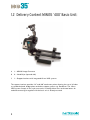
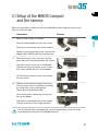
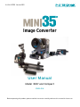
Art. Nr. # 22328 Version 0803
Image Converter
User Manual
Model ‘400’ and Compact
ENGLISH
Before operating this product, please read the instruction carefully and save this manual for future use.
E
Manufacturer Information:
The manufacturer of this product is
P+S Technik GmbH
Siemensstraße 12
85521 Ottobrunn / Munich
Germany.
Please find worldwide authorised representation and dealer on our homepage
http://www.pstechnik.de or send an e-mail to [email protected]
asking for the contact details.
Concerning any service and warranty requests, please contact your distributor
or P+S Technik GmbH directly.
Safety instructions:
Temperature range:
The Image Converter has been tested for a temperature range from 0°C to +50°C.
For field reports regarding more extreme temperatures please contact P+S Technik
Technical Support [email protected]
Maintenance / Special Tools:
Do not touch glass components with sharp objects.For cleaning do only use special
lens cleaning supplies. Refer all servicing to qualified service personnel.
Storage:
Please store the Image Converter in a dry and dust free place.
Disposal:
Please dispose broken components and devices correctly.
E
Contents:
1.
Mini Adapter:
1.1
1.2
1.3
1.4
1.5
1.6
Delivery Content MINI35 Compact………………………………………………………
Delivery Content MINI35 ‘400’… ………………………………………………………
Delivery Content Connecting Kits MINI35 ‘400’… ……………………………………
Accessories and Spare Parts MINI35… ………………………………………………
General Overview MINI35 Compact… …………………………………………………
General Overview MINI35 ‘400’…………………………………………………………
2.
Setup:
2.1
Setup of the MINI35 Compact… ……………………………………………………… 15
2.2
Setup of the MINI35 ‘400’… …………………………………………………………… 16
2.3
2.3.1
2.3.2
2.3.3
2.3.4
Operating elements of the Adapter………………………………………………………
Start / Stop…………………………………………………………………………………
Target Speed………………………………………………………………………………
Back focus Adjustment … ………………………………………………………………
Second iris diaphragm……………………………………………………………………
3. Tips and General Instructions…
4. Maintenance… …………………………………………………………………………
29
5. Technical Data …………………………………………………………………………
31
6. FAQ’s………………………………………………………………………………………
33
7. List of Suitable Lenses………………………………………………………………
43
8. Addresses and Contacts… …………………………………………………………
45
7
8
9
10
13
14
18
18
19
21
25
………………………………………………… 27
E
1.1 Delivery Content MINI35 Compact:
The MINI35 Adapter
1
A 1 – MINI35 Image Converter
B 2 – Hand Grips (side)
C 1 – Support Interface with integrated 15 mm LWS systems
D 1 – Integrated relay lens with Canon / JVC camera mount
E 1 – Camera mounting plate with clamp screw and power cable
The support interface provides 1/4" and 3/8" attachment points allowing the use of all industry standard tripods, bridge plates and other support systems e.g. Steadicam. The 15 mm
LWS system accepts all film style accessories including follow focus and matte boxes.
1.2 Delivery Content MINI35 ‘400’ Basic Unit:
B
A
C
B
A 1 – MINI35 Image Converter
B 2 – Hand Grips (top and side)
C 1 – Support Interface with integrated 15 mm LWS systems
The support interface provides 1/4" and 3/8" attachment points allowing the use of all industry standard tripods, bridge plates and other support systems e.g. Steadicam. The 15 mm
LWS system accepts all film style accessories including follow focus and matte boxes. An
ordered connecting kit togehter with the basic unit is already mounted.
E
1.3 Delivery Content Connecting Kits for MINI35 ‘400’:
1
The MINI35 Adapter
C
A
B
E
D
A 1 – Relay Lens with protective cap
B 1 – Mounting Plate
C 1 – Battery Plate with power cable
D 1 – Remote Control Cable
E 1 – Front cover or Viewfinder Holder (Canon/JVC only)
A Connecting Kit ordered with the `400´ basic module is already mounted when delivered.
Camera connecting kits must be purchased separately for each brand/model. For an up-todate list of available connecting kit visit our website www.pstechnik.de
Lens Mount and 15 mm rods for the lightweight support bridge are not included in the
delivery content of the MINI35 `400´ / Compact. They have to be acquired separately.
+++ SEE ALSO LENS SETS FROM P+S TECHNIK http://www.pstechnik.de +++
1.4 Accessories and Spare Parts MINI35
MINI35 Compact Image Converter
22694
MINI35 Compact for
Canon XL H1
incl. side handle, interface for 15 mm rods
& 35 mm bridge plate, pair of 15 mm rods
(150 mm), integrated connecting kit incl. intermediate lens, fixing plate for camera, adapter for Canon battery, lanc cable
One IMS lens mount needed
22695
MINI35 Compact for
JVC GY-HD 201 / 251
incl. side handle, interface for 15 mm rods
& 35 mm bridge plate, pair of 15 mm rods
(150 mm), integrated connecting kit incl.
intermediate lens, fixing plate for camera,
power cable, lanc cable
One IMS lens mount needed
MINI35 ‘400’ Image Converter
18000
MINI35 ‘400’ basic adapter
module
incl. 2 handles (top and side)
support bridge, provided for 15 mm rods,
interface for 35 mm bridge plate
for a complete system IMS lens mount
and connecting kit are necessary, no rods
included
MINI35 ‘400’ Connecting Kits
21034
MINI35 connecting kit for
JVC GY-HD 111 / 201 / 251
incl. intermediate lens, support bridge with
fixing plate for video camera, adapter for JVC
battery, standard holder for finder, non-lanc
cable
18770
MINI35 connecting kit for
Canon XL H1 / XL2 / XL1
/ XL1s
incl. intermediate lens, fixing plate for video
camera, adapter for Canon battery, standard
holder for finder, lanc cable
22524
MINI35 connecting kit for
Canon XH-A1 / G1
incl. intermediate lens, fixing plate for video
camera, adapter for Canon battery, cover
plate, lanc cable
21443
MINI35 connecting kit for
Panasonic HVX200
incl. intermediate lens, support bridge with
fixing plate for video camera, adapter for
Panasonic battery, cover plate, non-lanc
cable
10
E
MINI35 connecting kit for
Panasonic DVX100/A/B
incl. intermediate lens, fixing plate for video
camera, adapter for Panasonic battery, cover
plate, non-lanc cable
23886
MINI35 connecting kit for
Sony PMW-EX1
incl. intermediate lens, plate for fixing the
video camera, adapter for Sony battery, cover, plate, lanc cable, Batteries
Battery holder works with Sony Z1 type
22471
MINI35 connecting kit for
Sony HVR-V1
incl. intermediate lens, fixing plate for video
camera, adapter for Sony battery, cover
plate, lanc cable
20844
MINI35 connecting kit for
Sony HDR-FX1 / HVR-Z1
incl. intermediate lens, plate for fixing the
video camera, adapter for Sony battery, cover, plate, lanc cable
19748
MINI35 connecting kit for
Sony PD 150 / PD 170 /
VX 2000
incl. intermediate lens, fixing plate for video
camera, adapter for Sony battery, cover
plate, lanc cable
1
The MINI35 Adapter
19667
Lens Mounts for MINI35 – P+S Technik Interchangeable Mount System
18431
PL Mount
18384
Panavision Mount
20506
BNC-R Mount
23499
Professional F-Mount
18381
Nikon F-Mount
18382
Canon-EF Mount
22646
Canon-FD Mount
18383
Contax Mount
18380
Leica-R Mount
19906
Leica-M Mount
11
Breakout Box for MINI35
21225
MINI35 Breakout Box Kit 1 PAL
Breakout box with battery holder, Power cable MINI35, Sony DXF801 b/w finder PAL,
finder
cable, Video cable S-video/Fischer, Video
cable S-video/Cinch-Fischer
21254
MINI35 Breakout Box Kit 1
NTSC
Breakout box with battery holder; Power
cable MINI35, Sony DXF801 b/w finder
NTSC, finder
cable; Video cable S-video/Fischer; Video
cable S-video/Cinch-Fischer
21226
MINI35 Breakout Box Kit 2
Breakout box with battery holder; Power
cable MINI35; Video cable S-video/Fischer;
Video cable S-video/Cinch-Fischer
20745
Cmotion fastener
(for attachment of accessories)
Accessories for MINI35
21568
Shoulder Set
21229
MINI35 shoulder pad
21423
Hand grip with START/STOP
switch and cable
21422
Extension for hand grip, 1 piece
0449
2 – RS switch ON/OFF
(to use with MINI35, PRO35 and SI-2K)
21067
RS switch holder complete
(incl. RS switch holder, Cmotion fastener,
RS extension cable 0,8m)
21065
RS extension cable, 0,8 m
21390
Case for MINI35
12
incl. shoulder pad #21229, hand grip with
ON/OFF switch #21423, two extensions for
handgrip #21422
second side hand grip incl. in MINI35
designed for MINI35, video camera and accessories
E
A
INPUT – power connection
B
REMOTE connector
C
Image Plane / Pin for measuring
sharpness
D Control LED:
GREEN – Good speed control
RED – acceptable / low supply voltage
BLINKING – ERROR
E
Target-Speed Control wheel
F
Manual RUN (Start Adapter)
Does NOT start the
shooting!
G Iris diaphragm / ND Function
(adjustable ND Filter)
H Back Focus Adjustment Ring
I
3/8" & 2/3" thread for bridge
plate support
13
1
The MINI35 Adapter
1.5 General Overview MINI35 Compact:
1.6 General Overview MINI35 ‘400’:
A
INPUT – power connection
B
REMOTE connector
C
Image Plane / Pin for measuring
sharpness
D Control LED:
GREEN – Good speed control
RED – acceptable / low supply voltage
BLINKING – ERROR
E
Target-Speed Control wheel
F
RUN Button (Start Adapter)
Does NOT start the
shooting!
G Iris diaphragm / ND Function
(adjustable ND Filter)
(depending on camera integrated in relay lens or with
camera’s fixed lens)
H Back focus adjustment (depending on camera integrated
in relay lens or with camera’s
fixed lens)
I
14
3/8" & 2/3" thread for bridge
plate support or tripod
E
2.1 Setup of the MINI35 Compact
and the camera:
Follow the steps below to properly attach the MINI35 Compact Image Converter to your
Canon or JVC camcorder
Instructions
2
Make sure the camera is turned off.
Setup
1.
Pictures
Remove the detachable lens from the camera.
Remove all custom plates from camera bottom.
Slide the mounting plate back until it touches the
adapters back side by releasing the black knob.
2.
Remove the clamp screw from the mounting
plate and screw into tripod thread of the camera
Attach the camera to the rear of the MINI35
Compact, by lining up the dots on the camera
lens mount and the relay lens of the adapter.
To attach the Canon cameras you need to
turn the camera.
3.
Slide the mounting plate towards the camera
until the clamp screw is completely covered by
the clamp shoe in the mounting plate.
Tighten by turning the black knob.
Connect the power cable to the camera and
then to the adapter.
Attach 15 mm lightweight rods to the support
interface at the front of the image converter.
The JVC GY-HD 250 is equipped with a custom dovetail plate, which has to be
removed before installation in the MINI35 Compact.
15
2.2Setup of the MINI35 ‘400’
and the camera:
Follow the steps below to properly attach the MINI35 Image Converter to your camcorder
A
B
C
D
E
Viewfinder Holder
Top Cover
Lock Ring
Relay Lens
Spring loaded pad
Instruction
F
G
H
I
J
Support release Lever
Camera Screw
Battery Holder
Spacer for XL1 / XL1S
Bottom Screws
Explanatory Notes
1
Make sure the camera is turned off.
2
Remove the relay lens from the MINI35: The relay is attached to the rear of the
MINI35 via a bayonet type mount.
a. Locate the lock ring c.
b. Rotate the lock ring c counter cloThe lock ring c is the ring located in the front
ckwise.
of the relay lens, nearest to the body of the
MINI35.
16
E
Explanatory Notes
Attach the relay lens onto the camera:
a. Line up the red dots
b. Engage the lens in the mount
c. Rotate the lens until the lock clicks in
place.
The relay lens attaches like any other
XL mounted lens.
4
Prepare the MINI35:
a. Release the two screws j on the
bottom of the camera support, and slide the support toward the rear battery
holder.
b. Release the lever f, push the pad
e down and lock it in that position by
tightening lever f.
5
Mount the relay lens (now attached to
the camera) onto the MINI35 Image
Converter:
Engage the relay into the back port of
the MINI35 and secure it in place with
the lock ring c.→
When the camera is installed for the first
time, it is easier to start by sliding the camera
support out of the way.
The camera support platform has a springloaded pad in the center that adjusts for the
height of the camera. The knob with a lever
f, at the back of the camera platform, locks
the spring-loaded pad in place. By releasing
that knob, the spring will push the pad to its
highest position making the mounting of the
camera difficult.
a. Open the lock ring c.
b. Line up the relay lens into the port holding
the camera by its top handle. Make sure the
locating pin is fully engaged.
c. Close the lock ring c clockwise to secure
the relay lens.
Be sure the camera does not accidently
disengage.
6
a. The big knurled knob g through the
camera platform has to line up with the 1/4"
Slide the camera support bracket under threaded hole on the camera bottom.
b. Start engaging the thread of the knob in
the camera and attach the knob g to
the bottom of the camera:
the thread of the camera but do not tighten it
yet.
c. Release the lever f at the back of the
platform to allow the spring-loaded pad e to
get in contact with the base of the camera.
Finish tightening the knob g at the bottom of
the platform.
Attach the camera support:
Lock the lever f at the back of the
camera support and lock the screws at
the bottom of the camera support.
The different setup between the XL1 and
the XL2 requires to attach a little plate (XL2
engraved) under the platform. This adjusts for
the different camera heights.
17
2
Setup
3
Instruction
2.3Operating elements of the camera:
2.3.1 Start / Stop:
If the Image Converter has been started manually
(RUN-Button g) a pressure on the VTR-start button
of the camera activates ONLY the recording; the Image Converter remains in RUN-Mode.
Manual “RUN” status
VTR signal
Result
OFF
VTR ON*
VTR OFF
Image Converter ON
Image Converter OFF
ON
VTR ON*
VTR OFF
Image Converter ON
Image Converter ON
* While the camera is recording, the RUN-Button g is not active
The Image Converter does NOT start automatically after changing battery or switching on/off the camera (this is not a failure, but it saves electricity and increases the lifetime of the mechanical components of the unit).
Check BEFORE shooting, whether the Image Converter:
a) is already running (manual start) or
b) is started automatically with the camera
TIP: Start the shooting AND the Image Converter
SAVELY with an external start/stop switch (e.g. with
the P+S Technik RS switch #20449 or other compatible switches). Hence you can almost screen
out that the Image Converter is not running during
recording.
The utilization of the RS switch makes a simultaneous starting of MINI35 and camera possible.
18
E
2.3.2 Target Speed:
Next to the RUN LED is the adjustment wheel for regulation of the
speed of the oscillating target.
What is the “Target”?
The target is an element out of glass inside the Image Converter, which is located at the position of the image plane of the MINI35. Often described misleadingly as focusing screen or
ground glass, it fulfils a similar function in the unit. It displays the picture, which is projected
from the lens.
The equivalent depth-of-field effect of 35 mm film is achieved only because of the special
composition of the target surface and the physical size of the displayed picture.
Without the target glass the Image Converter would only be a ‘relays lens’. The angle of view
would be displayed correctly to the camera, but the depth of field would be identical to “normal” lenses for this camera.
Because of the motion of the target (motion blur) the structure of the glass surface is blurred;
but it is visible when the Image Converter is switched off. Depending on different factors (see
chart) it can be worked with lower or it must be worked with medium speed.
Low speed
Medium / high speed
Possible in case of low-resolution
cameras
Possible in case of long exposure time
Possible in case of long range lenses
Possible in case of open aperture
Necessary in case of high-resolution
cameras
Necessary in case of shorter exposure time
Necessary in case of short range lenses
Necessary in case of dimmed or light-weak
lenses
+ very quiet
– maybe louder operating noise
IMPORTANT: The adequate adjustment of the target speed has to be tested BEFORE
shooting. The evaluation should be done with a high quality monitor with a resolution analogue to the camera’s resolution.
19
Setup
2
WHEN is it necessary to adjust the target speed?
– In case of changing the camera
– In case of modification of exposure time / frame rate
–In case of working under extreme circumstances, e. g. low temperature.
How do I adjust the “right” target speed?
Tip 1: In order to achieve best results, please follow these rules of thumb:
– If possible work with open lens aperture.
A low depth of field reduces the risk of a visible target and leads to the desired
typical look of the 35 mm film picture.
The second aperture or the optical filter is helpful for the correct exposure.
– Use common exposure times like 1/48 s., 1/50 s., and 1/60 s..
The shorter the exposure time, the sharper the display on the target glass.
(it reduces the motion blur!)
We assume that a not visible target glass guarantees ideal results. A lot of user use the target
speed in a creative way and add to the picture intentionally grain e. g. by running the target in
extremely slow speed.
This is especially in case of high-resolution or highly compressed shooting systems only after
intensive tests advisable, because the above named effect can influence the actually recorded picture in a negative way. (Results are often clearly visible compression artefacts in the
recorded material). This is only ONE of the possibilities of the adjustment; a lot of users have
surely developed their own way.
Tip 2: A practical alternative for adjusting the correct target speed (especially for high resolution cameras) is to synchronize the target with the electronically shutter of the camera. Here the resulting artefacts are made visible first with the help of a high resolution monitor and then the ideal adjustment of the speed is worked out.
A maximum speed is NOT always ideal. Similar to the adjustment of a running
film camera to the flickering of a monitor, ONLY a speed for the set exposure time / frame rate is appropriate.
1. Focus the camera on a constantly lit surface (this can be for example grey or
coloured). Light preferably for a high aperture, e. g. 16/22; do not overexpose.
2. Check flange focal distance and exposure time.
Set the controller of the target speed on a low value and start the MINI35.
3. Close the iris of the front lens until you can see movement artefacts between target and shutter on the monitor.
20
E
4. Increase the speed as long as the structure stops (in synchronization with shutter) – the structure is “frozen”.
You are going to realize that countervailing artefacts become visible in case of a
further increment of the speed.
5. Note / mark the best possible setting of the speed and re-open the aperture for the
“normal” shooting.
2
Setup
Like this you are able to minimize eventually appearing artefacts, because even at a high aperture value (and a high depth of field) only stopped structures (converter OFF) become visible
and not moving ones.
MINI35 Modell ‘300’
The difference between the MINI35 Model ‘300’ and the Model ‘400’ is the movement of
the target and the diameter of the optical channel. The rotating ground glass of the Model
‘300’ results in a dot in the middle of the image, which is particularly visible in against-thelight-shots. Therefore the movement of the ground glass has been changed into an oscillating
movement for the Model ‘400’.
The first camera models required a smaller diameter of the optical channel. When using the
Model ‘300’ with some newer camera models problems, like black frames, can appear. This is
the reason why the MINI35 Model ‘400’ has a larger optical channel.
+++ All previous PRO35 Image Converters can be upgraded to MK II, for that purpose contact P+S Technik or your local distributor. +++
2.3.3 Flange focal distance and Back focus:
There are two lens mounts on the MINI35 Image Converter: on the lens side (PL Mount,
Nikon…) and on the camera side (Bayonet Mount). Hence there are two possibilities to adjust the flange focal distance:
1. The lens mount for the film and photo lenses (on the front of the Image Converter); has a
factory preset flange focal distance, identical to film cameras.
2. The camera side Mount of the MINI35 can be adjusted with the back focus ring on the
relay lens or with the focus ring on the camera’s lens.
21
When is an adjustment of the camera side flange focal distance / back focus
necessary?
–
–
–
–
In case of changing the camera
In case of variation of temperature + / – 10 °C
In case of high mechanical load onto the mount of the camera (heavy zoom lens or similar)
After transportation of the unit respectively other heavy agitation.
How can the back focus be controlled and adjusted?
1. Adjusting back focus in preparation / test room:
Check if the actually measured distance on the lens leads to a correct visual sharpness.
Example: Place the test chart precise 3 m (or another, exact calibrated distance at the lens)
distant from the image plane and adjust the measured distance at the lens. Check the result
on a high-resolution monitor.
Instruction
Explanatory Notes
1
Mount a film lens to the Image Converter.
Select a mid range film lens; around
50 mm.
2
Place a focus chart at a reasonable distance
and set the focus of the film lens at that
distance.
2.1 Turn the Image Converter ON.
Open the adjustable ND FILTER to Position 0.
2.2 Close the iris of the film lens to around T4.
2.3 Turn the back focus adjustment ring on relay
lens or camera’s fixed lens.
Turn the ring to adjust for best sharpness.
2.4 Tighten lever 8.
The MINI35 Image Converter is precisely adjusted for the camera.
22
Use a good quality monitor to evaluate the picture.
E
2. Adjusting flange focal distance in the field:
Rule of thumb: If you are seeing the structure of the target glass clearly sharp while having
switched off the Image Converter (OFF), the flange focal distance is correctly adjusted.
2
Explanatory Notes
Mount a film lens to the MINI35.
Select a mid range film lens
(around 50 mm)
Use a white chart.
2
Set a white chart at a reasonable
distance to fill the image.
Setup
1
Instruction
2.1 Turn the MINI35 unit OFF.
Open the adjustable “ND filter” to Position 0.
2.2 Close the iris of the film lens far enough to allow
the video camera to show the grain pattern of the
target glass. Use a good quality monitor to evaluate the picture.
2.3 Turn the back focus adjustment ring on relay lens
or camera’s fixed lens
2.4 When the grain pattern is sharp, the MINI35 is
precisely adjusted for the camera.
23
Example for test charts
Test charts to control the back focus are available from P+S Technik, or:
– ZGC (Putora)
http://www.zgc.com/zgc.nsf/product/putora
– Image Engineering (Esser)
http://digitalkamera.image-engineering.de/index.php/Produkte/Testcharts
– DSC-Labs
http://dsclabs.com/resolution.htm
24
E
2.3.4 Second iris diaphragm “continuous ND-Filter”:
In the practical handling with the MINI35 Image Converter, the aperture of the utilized
lens is mainly used for the definition of the desired depth of field. The real exposure of the
camera results – like in classical film productions – from light setup, from optical filters
(in front of the lens as well as internal ND-Filter) and / or from the utilization of the second iris
diaphragm:
IMPORTANT: The visual depth of field does NOT change by using the second iris diaphragm! Another aperture, which is located behind the ground glass, is only a kind of light
valve, because of the projection of the picture on the target. Consequently a precise control
of exposure is possible anytime
TIP: Mask the working aperture during the first days of production. Like this you get
used to the exposure correction with the second diaphragm.
25
2
Setup
The MINI35 setup offers a second iris diaphragm. It is either integrated in the relay lens of the
connecting kit/ the adapter and marked with numbers or you use the iris of the cameras fixed
lens. Use this second iris to make a correct exposure calculation comparable to a ND filter.
Loss of light:
The MINI35 Image Converter has beside the target also other optical elements. An explicit
description would go beyond the scope of this manual. Therefore there should only be named
the main components:
1. Safety glass in front of the “target” (avoids permeation of dirt particles into the Image
Converter)
2. Target glass – see above. This is at the same time the image plane (white engraving on
the body)
3. Prism block: Makes an optical adjustment of the image position possible (side-inverted
projection of the lens on the target). Therefore also old cameras can be used unlimited
with the Image Converter – the image is always projected correctly.
4. Adjustment lenses and second iris diaphragm: the rear part of the converter includes an
intermediate lens which scales down the 35 mm image projected on the target to the size
of the camera’s CCD (2/3" or 1/2") and corrects the light beam for the three focal planes
(red, green and blue) of the video cameras. Apart from this the intermediate lens includes
the back focus adjustment ring (see chapter above) and the second iris diaphragm (see
chapter above)
Naturally lenses NEVER work without loss of light. Also the optical system inside the threechip camera (prism) is often limited to maximum F1.4. Approximately 1 aperture is lost because of the projection of the picture onto the target glass and the other optical components.
The maximum aperture of the lens used has to be considered as well. Therefore check BEFORE shooting the loss of light resulting from your precise configuration of lens and camera.
When using a camera with a permanently integrated lens on the MINI35 Image Converter,
the so called “Ramping” takes effect. Some lenses of these cameras have in their maximum
tele position a further reduced light intensity; please keep this in mind when testing the
adapter.
The P+S Technik MINI35 COMPACT Adapter does not have an own prisma system for
the correct image position. Like this the loss of light could be reduced clearly. But in this case
the utilized camera has to be able to turn/ record the image. Therefore check BEFORE shooting, if your viewfinder, monitor and post production are able to handle turned images.
26
E
3. Tips and General Instruction:
Film-Look: Which elements are important?
– Framerate:
Film works only with complete pictures, that means progressive with 24 or 25 Hz.
Television systems work currently for the most part with half pictures (interlaced), that
means with 50 or 60 Hz. The higher the frame rate, the higher is also the motion
resolution. A football game with “only” 24 Hz would not be as informative for the viewer as
football game with 50 Hz.
– Motion blur:
One characteristic of the so called film look is the motion blur. Low frame rate / long exposure time lead to a higher motion blur compared to television – benefit from this creative
tool.
– Shutter effect / strobing:
Is your pan jerky? Probably your pan velocity is not adjusted to your frame rate (and your
motion blur). Check the pan velocity against the focal distance, e. g. in the manual of
the ASC (American Society of Cinematographers).
Also newer monitors show the pictures often “jerky”. Chose your equipment accordingly to
your reporting (TV/cinema) and your method of recording (interlaced/progressive).
– Method of recording:
INTERLACED is still a widespread method for increasing the motion resolution
(50/60 Hz). Use this method creatively, e. g. for a later slow motion (Example: convert
50/60 Hz interlaced to 50/60 Hz progressive, afterwards rendering with 24/25 frames/s.).
De-interlaced is often used for the print out.
PROGRESSIVE is used for printing out the material; this is often more close to the film
look, because of a lower motion resolution (24/25 Hz).
– Compression:
Unfortunately the recording quality is highly dependent on the format of recording.
A lot of today’s used data compression programs are for example highly sensitive to noise
or quickly changing picture contents. While recording do not only trust your picture on
the monitor (it shows often the uncompressed signal), but test how the recorded signal is
behaving in different recording situations (see also: TARGET SPEED above).
27
3
Tips and General Instructions
– Exposure time:
The common shutter speed result for film cameras result normally from the frame rate.
This is mostly 1/48 s., 1/50 s. or 1/60 s., some applications request a shorter exposure
time.
Electronic cameras work generally in the same manner, but the consolidation between
frame rate and exposure time is not as steep. This means at for example 60 frames
per second there is also a longer exposure time possible (up to 360 degrees Hell sector
= 1/60 s.)
– Depth of field:
Like the human eye has a selective perception, also filmmakers and cinematographers use
the depth of field for calling the attention of the viewer to specific things or also to detract
from something.
At the same time the effective size of the picture plays an important part: The larger it is,
the lower is the depth of field; small amateur cameras work often with very small sensors
and that’s why their picture comes across as unnaturally sharp. The P+S Technik Image
Converter allow now the identical depth of field like in 35 mm film on an electronic camera
with a considerably smaller size of the sensor.
– Choice of lens:
The choice of lens is – especially in combination with high-resolution cameras – clearly
visible. Therefore test the lenses before shooting! See a list with applicable lenses in the
annex.
– Aspect ratio:
Because of the fact that the human eye has a considerably larger horizontal field of vision
than a vertical one, a lot of films used already very early an analogous larger aspect ratio
for achieving an impressively large screen projection (Example: Cinemascope).
Like this a different visual effect is produced for the viewer only because of the picture
size.
28
E
4. Maintenance:
Generally the P+S Technik Image Converter are designed to a maintenance-free use on the
shooting location. But because of the number of mechanical components service is required
from time to time. This concerns especially the regular cleaning of the unit.
Like in classical film, the cleaning at the shooting location is limited on keeping clean the
optical unit, which means the safety glass inside the Image Converter and the back-lens of
the system.
Find detailed instructions regarding the cleaning in the separate service manual of the Image
Converter.
4
P+S Technik offers workshops for technicians, which explain the service in detail.
Please contact [email protected].
Maintenance
Please use only appropriate material for blowing out and use cleaner only in case of stubborn dirt.
29
30
E
5. Technical Data
MINI35 ‘400’ &
Camera with
fixed lens
MINI35 Compact
Relay lens
Relay lens
Relay lens
MINI35 Lens Mount
(converter to lens)
Interchangeable
Mount System IMS
Lens mount by
choice
Interchangeable
Mount System IMS
Lens mount by
choice
Interchangeable
Mount System IMS
Lens mount by
choice
Tuning for Shooting
Sensor
Back Focus integrated in relay lens
Back Focus adjustment with camera’s
manual focus
Integrated Back
Focus
Length of MINI35
Digital unit
345 mm / 13.58 in
345 mm / 13.58 in
200 mm / 7.87 in
Weight
2850 g / 6.27 lbs
3000 g / 6.6 lbs
1550 g / 3.42 lbs
MINI35 Camera Mount
(converter to camera)
5
Frame position
Upright,
Emulsion Side Up
Upright,
Emulsion Side Up
Upside down,
mirror-inverted
(camcorder offers
electronic image flip
function)
MINI35´s
Iris Diaphragma*
Built-in relay lens for
light reduction
Camera iris for
light reduction
Built-in for
light reduction
Current consumption
300mA / 7.2 V
300mA / 7.2 V
300mA / 7.2 V
Power supply
Adapter Battery
connected via 2 pin
cable, extra battery
needed
Adapter Battery
connected via 2 pin
cable, extra battery
needed
Power cable to
camera
Image Target Frequency
Variable speed
Variable speed
Variable speed
Eccentric
marked 0 - 8
marked 0 - 8
marked 0 - 8
Recommended Operating Temperature Range
0 - 50 ºC
0 - 50 ºC
0 - 50 ºC
*Behind lens, no effect on depth focus
31
Technical Data
MINI35 ‘400’ &
Camera with
detachable lens
32
E
6. FAQ:
1. Do I have to send my camera to P+S Technik to do some mechanical or electronic changes before I can use the MINI35 Image Converter?
No, there is no need for any modifications, therefore there is no need to send the camera
to us.
3. What do I basically need for a complete MINI35 Image Converter solution?
For a complete solution the following items are necessary in any case:
1) The MINI35 Image Converter basic unit.
2) A compatible lens mount for the film or photo lenses, you like to shot with.
3) The compatible Connecting Kit for the digital video camera, you want to use the
Image Converter with.
We explicitly recommend the use of a remote switch in order to guarantee an easily
operated start and stop of both, camera and Image Converter simultaneous. Corresponding switches are available from P+S Technik (RS switch #20449), ARRI and other
suppliers.
4. What additional accessories does P+S Technik offer?
Additional accessories, like different lens mounts, a complete shoulder set (including a
shoulder pad, hand grip extensions and hand grip with an ON/OFF switch), 15 mm rods
for the prepared light weight support and a case for your MINI35 system are available.
Other very helpful accessories for the MINI35 are the matte box and follow focus systems, which allow the focus puller to work professionally with focus and filters, etc.
Further on we offer the MINI35 Breakout Box. It provides video outputs for a quality
viewfinder and additional monitoring. From here power is distributed to the Image Converter, camera and various accessories. By using a professional battery system you will
prolong operation time. The battery system together with the viewfinder is the perfect
upgrade for extensive shoulder shots as the viewfinder can be adjusted for eye height
33
6
FAQ
2. How does the MINI35 work?
The basic principle: The MINI35 achieves a mechanical and optical adaptation of 35 mm
film lenses to the most popular 3-CCD 1/3" DV and HDV cameras. The MINI35 is a modular system and therefore adaptable to your video camera with a compatible Connection Kit. You can find a list of the supported cameras on our website www.pstechnik.de.
How does the MINI35 work: The chip size (image field) of your digital video camera is
artificially enlarged by an intermediate projection, therefore transferring the 35 mm lens
characteristics (e.g. angle of view and depth of field) to the video camera.
The deciding point is the two stage configuration: The image, drafted by the film lens is
projected onto an oscillating ground glass, called target. This target is in the same position, as the film plane in a 35 mm film camera. For this reason the scale of reproduction, as
well as depth of field and angle of view show the “film like quality”, similar to a 35 mm film
camera. In a second step this real image is resized and projected onto the CCD-video
chip. Since this is just a linear squeeze of a two-dimensional image all optical characteristics, like depth of field and angle of view stay the same.
This means that the video chip is not the place of image creation (this is the target!), but
of image recording.
and the battery holder helps to balance the system.
For further information please refer to Datasheet MINI35.
5. Which cameras work together with the MINI35?
Connecting Kits for the MINI35 are available for the following digital video cameras:
* Canon XL-1; XL-1s; XL-2; XL-H1; XH-A1; G1
* JVC GY-HD 111 / 201 / 251
* Panasonic DVX100 / A / B
* Panasonic HVX200
* Sony PD150; PD170; VX2000
* Sony HVR-V1;
* Sony PMW-EX1
Every Connecting Kit contains everything needed to attach the corresponding camera
to the MINI35 (i.e. Intermediate lens, Plate/Support bridge for fixing the camera on the
MINI35, battery adapter, lanc/non-lanc cable)
6. Which lens mounts are available for the MINI35?
The following lens mounts are available and easily changed (even on set) for the MINI35:
* PL Mount
* Panavision Mount
* BNC-R Mount
* Professional F-Mount
* Nikon F-Mount
* Canon EF-Mount
* Canon FD-Mount
* Contax Mount
* Leika R Mount
* Leika M Mount
7. How does the imagery – the MINI35 creates – look like?
Basically the MINI35 makes a limited depth of field possible for 1/3" video cameras as
up to now it was applicable only in connection with 35 mm film. Thereby the MINI35 enables film-makers to use limited depth of field as another creative instrument for shooting
on video. At the same time the targets structural pattern affects the image comparably to
a light soft-focus and low-contrast filter and adds a film grain-like effect to it. In contrast
to a textbook-perfect, hard and clean digital video, the MINI35 generates images, appearing more lively and softer. Altogether the look and feel is similar to the imagery you are
used to from 35 mm film.
8. What is meant by “target”?
The “target” is the core of the Image Converter. It is a grinded optical glass, similar to a
ground glass, used in viewfinder systems of film cameras. The image, drafted by the film
lens, is projected onto this target and in a second step captured by the CCD-chips of
your digital video camera. In order to blur the target’s structural pattern, it is set into an
oscillation movement.
34
E
9. What kind of target (ground glass) is used in the MINI35?
The target, used in the MINI35, is a specially grinded optical glass, that minimizes light
loss.
10. Can I edit the same way?
Yes. You can edit the same way you are used to.
11. Is there a light loss using the MINI35?
Yes, for the MINI35 you can assume a light loss of 1.2 stops. Since the light loss is not
linear this is the “worst case” value.
12. How do I get started?
Since shooting with the MINI35 is similar to shooting with film we, recommend to test
the complete setup in detail in order to familiarize with your Image Converter and its
specific features!
14. Do I need a power supply for the MINI35?
Yes, you need a power supply to run the motor of the MINI35 for the oscillation of the
target. There are different possibilities for power supply.
1) Basically you can use the standard DV brick batteries, that come with your digital
video camera. Corresponding battery adaptors are delivered with each Connecting Kit.
2) The usage of our “Breakout Box” provides the possibility to generate one single power supply for both, camera and Image Converter in connection with professional battery
systems like Anton Bauer, PAGlok, Sony V-Mount and IDX.
15. Why is there an ON/Off switch on the MINI35 Image Converter?
As specified in FAQ # 2 the image generated by the 35 mm front lens is projected in a
first step on a ground glass-like target. In a second step this image is resized by a relay
lens system to the smaller-sized video chip.
The target itself carries a structural pattern to visualize the image created by the front
lens. If the target is motionless, this pattern is stamped on the image and appears like
some kind of dirt on the lens.
In order to blur this structural pattern the Image Converter has to be switched on. The
target starts oscillating whereby the structural pattern appears in a film grain-like manner.
16. Why is there a speed control on the MINI35 ‘oszi’ Image Converter?
As specified in FAQ # 15 the image generated by the 35 mm front lens is projected in a
first step on a ground glass-like target. In a second step this image is resized by a relay
lens system to the smaller-sized video chip.
The target itself carries a structural pattern to visualize the image created by the front
lens. If the target is motionless, this pattern is stamped on the image and appears like
some kind of dirt on the lens.
35
6
FAQ
13. Is it possible to start shooting with the MINI35 right away?
Yes, this is possible, but since shooting with the MINI35 is similar to shooting with film,
we recommend to test the complete setup in detail in order to familiarize with your new
Image Converter and its specific features! Please mind the necessity of Back focus.
In order to blur this structural pattern the target is set into an oscillating movement,
whereby the structural pattern appears in a film grain-like manner.
The speed control now diversifies the targets oscillation frequency. This provides the
opportunity to eliminate disturbances or interferences caused by high shutter speeds or
to achieve different grain effects, also depending upon the iris opening of the front lens.
17. How to adjust the target oscillation speed?
For information on the adjustment of the target’s oscillation please see page 21.
18. What is the iris in the intermediate lens for? (only with Canon and JVC – for all
the other supplied camera systems please read on anyway!)
The intermediate lens of the Canon and JVC Connecting Kit is equipped with an iris.
However this iris only serves to light reduction. This offers the opportunity to shoot in
bright environments with a wide opened front lens aperture (in order to obtain a narrow
depth of field) without overexposing the video cameras CCD-chip. Therefore the Image
Converter’s iris is comparable to a variable ND function. But there is no influence on
depth of field, because the light source relating to this iris is not a three-dimensional
environment but the two-dimensional image on the target, which obtains just one focus
plane. That is why the depth of field isn’t influenced by the Image Converter’s iris.
For all the other supplied camera systems (Sony and Panasonic) the reduction of light,
described above, is obtained with the aid of the internal aperture of the video camera. In
this case there is no influence on the depth of field as well.
In summary: For a camera setup with the MINI35 Image Converter the aperture of the
front lens serves to adjust the image’s depth of field; the iris of the intermediate lens and
accordingly of the video camera only serves to adjust exposure.
19. How does the user adjusts the exposure (without affecting the depth of field
by closing the front lens)?
In order to control exposure (i.e. when light is too intense like in bright daylight) without
affecting the depth of field, we recommend to use the iris of the Image Converter.
If this ND function is insufficient and the image remains overexposed, closing the film
lens’s iris may not offer the required limited depth of field or may project too much grain
on the video image. Two possible remedies:
1) Use the ND function of your video camera or
2) Use a ND filter in front of the film/photo lens to decrease the light, entering the system
We do not recommend increasing the shutter speed of the camera in order to control
exposure. In this case please consider, that the visibility of the target’s structural pattern
changes and might cause disturbance or interferences in your image. Although it’s possible to eliminate these interferences by adjusting the speed control of the target.
20. Is it possible to adjust exposure by the camera’s shutter speed? What has to
be considered in this case?
When decreasing the shutter speed of your camera in order to control exposure please
consider, that the visibility of the target’s structural pattern changes and might cause
disturbance or interferences in your image.
36
E
21. What has to be considered when shooting with variable frame rates?
When decreasing the shutter speed of your camera in order to shoot at variable (higher)
frame rates, please consider, that the visibility of the target’s structural pattern changes
and might cause disturbance or interferences in your image. By adjusting the target’s
speed control it is possible to eliminate these interferences.
22. Why is it not recommended to adjust exposure by stopping down the front
lens aperture?
There are different reasons:
1) The higher the T-stop (T4.0 or higher i.e. T11), the more apparent the grain effect will
be. The other way around: the lower the T-stop (T4.0 or lower i.e. T1.2), the less apparent the grain effect will be.
2) When closing the front lens aperture more than about 2.5 stops, the depth of field
is comparable to a normal video lens. In this case it makes no sense shooting with the
MINI35 and film lenses.
In order to control exposure it is more advantageous to use the Image Converter’s or
camera’s ND function.
24. When stopping down the aperture of the front lens at T4.0 or further, the structural pattern of the target becomes apparent. How can I avoid this pattern to
appear on my imagery?
In order to control exposure (i.e. when light is too intense like in bright daylight) without
affecting the depth of field, we recommend to use the iris of the Image Converter.
If this ND function is insufficient and the image remains overexposed anyway, closing
the film lens iris may not offer the required limited depth of field or may project too much
grain on the video image. Two possible remedies:
1) Use the ND filter of your video camera or
2) Use a ND filter in front of the film/photo lens to decrease the light entering the system
We do not recommend to increase the shutter speed of the camera in order to control
exposure. In this case please consider, that the visibility of the target’s structural pattern
changes and might cause disturbance or interferences in your image. Although it’s possible to eliminate these interferences by adjusting the speed control of the target.
25. Is it possible to use the whole tolerance of the film lens aperture together with
the MINI35?
We advise not to use the whole tolerance of the film lens aperture together with the
MINI35. Stopping down the aperture of the front lens at T4.0 or further unveils the structural pattern of the target.
In order to control exposure (i.e. when light is too intense like in bright daylight) without
affecting the depth of field we recommend to use the Image Converter’s iris.
37
6
FAQ
23. When testing different shutter speeds I realised that at 1/100 sec the structural pattern of the target becomes apparent. Which shutter speed do you recommend?
We recommend to use standard shutter speeds with the current version of the MINI35.
26. What is the highest aperture stop I can use without getting grain from the
target?
We recommend to avoid stopping down the front lens aperture further than T4.0.
27. The distances engraved on the film lens’s focus ring do not match to the measured distances to focused objects. Is it due to a back focus displacement?
Yes. You have to adjust the back focus at the Image Converter.
28. How do I create a clean image?
For creation of a clean image please consider the following items:
* Back focus adjustment
* adjust the target’s oscillation speed
* control the camera’s shutter speed
* do not stop down the front lens further than T4.0
* Try setting the camera to manual mode and limit the gain to 0 db or even –3 db
29. Which support systems am I supposed to use with the MINI35?
* By default the MINI35 is prepared for the use with 15 mm light weight support (15 mm
rods not included!)
* The bottom plate of the MINI35 is also prepared for accession to 35 mm bridge plates
and therefore applicable with 15 mm and 19 mm heavy duty support.
30. Why do I need a support system?
* In order to stabilize your setup
* Offers the possibility to connect accessories like matte box or follow focus to your
MINI35 setup
31. Can I use a professional viewfinder with the MINI35 setup with Panasonic or
Sony camcorders?
Yes, this is possible! Using the breakout box provides the option to connect a Sony DXF
801 b/w professional viewfinder (PAL/NTSC).
32. Which lenses can be used together with the MINI35?
You can use all available film lenses with PL-Mount, able to expose the N35 Academy
format (22 mm x 16 mm):
* Zeiss Master Primes (T1.3)
* Zeiss Ultra Primes (T1.9-T2.8)
* Zeiss Super Speed Lenses (T1.3)
* Cook S4
* Cook S4 Zoom T2 15-40 mm
* Cook Zoom T3 18m-100 mm
* Angenieux Optimo Zooms
* Zeiss Distagon: (focal length 85 mm or more!)
Zoom lenses and Zeiss Distagon lenses might cause vignetting. These lenses
should be tested before shooting individually!
38
E
Furthermore the following lens mounts are available and can be used with the corresponding lenses:
* Panavision Mount
* Nikon Mount
* Canon EF Mount
* Contax Mount
* BNC-R Mount
* Leica Mount
34. Is it true that I have to use High Speed Prime lenses with the MINI35 and not
the Standard Speeds?
No, it is not true that you have to use Zeiss High Speed primes. The advantage of the
HS lenses is the fact, that with a T 1.3 the HS lenses have a bigger aperture and accordingly a smaller depth of field than standard speed lenses. Although you can use
other lenses, i.e. Ultra Primes or photo lenses: It is important to check each lens before
shooting, because you never know what could happen. That is what camera assistants
do before shooting with film cameras and it should be the same before shooting with a
MINI35 and film or photo lenses.
35. Is it possible to use 16 mm film lenses with the MINI35?
The MINI35 is developed for the use with 35 mm film lenses, that expose the whole
N35 Academy format. Since 16 mm lenses are styled for smaller frame sizes, vignetting
problems may occur. As a rough guide 16 mm lenses, whose rear lens is as large as a
one €Euro coin should work. But if you decide to use 16 mm lenses, please test it before
shooting!
36. Does the focal length of the lens I’m using change?
No, the focal length of the lens does not change. It stays the same!
37. Is the angle of view of the film lenses I’m using affected by the
Image Converter?
Neither the focus length nor the angle of view is affected by your Image Converter. For
all 35 mm film lenses the image properties comply with the properties of a N35 film camera.
For further understanding: In principle every 35 mm film lens draws a round image onto
the film gate of a film camera (most 35 mm film lenses draw an image diameter of 30 mm
in order to expose S35 formats as well as N35 formats, although a diameter of 27,2 mm
39
6
FAQ
33. Which lenses do you recommend to use and why?
The following lenses work perfectly with the MINI35:
* Zeiss Master Primes
* Zeiss HS Primes
* Cook S4
* Zeiss Ultra Primes
You always have to keep in mind, that you have a light loss of 1.2 stops with the MINI35.
The faster the lens, the more light is left for exposure! Over and above a wide opened
front aperture creates a smaller depth of field.
suffices to expose the N35 formats). This film gate or an accordant format mask cuts out
the framing as desired.
For the MINI35 it’s nearly the same: The fore part of the Image Converter is designed simular to a N35 film camera: The film lens draws a round image onto the Image
Converter’s target, which is in the same position as the film stock in a film camera. In a
second step a 27,2 mm image circle (remember: this is satisfactory for N35 formats!) is
then squeezed to the diameter/diagonal (6 mm) of the 1/3" CCD-chip. The CCD-chip
then serves as a quasi format mask and cuts out the framing according to the CCDs
size. In conclusion it is to say that the CCD-chip defines, what is recorded by the video
camera!
38. Is the focal length or the angle of view of the photo lenses I’m using affected
by the Image Converter?
The focal length of your photo lenses is not affected by the MINI35.
Stills Photographers: Compared to still photography the angle of view changes (gets
smaller!). In order to choose the right focal length for a desired angle of view please refer
to [FAQ: Translate Focal length].
Cinematographers: If you are used to shoot on film lenses, you can handle a photo lens
the same way like a film lens. I.e.: on the MINI35 the angle of view (as well as the focal
length and depth of field) of a 50 mm photo lens is the same as of a 50 mm film lens!
Differences remain in order to the handling (i.e. focus).
39. How can I translate focal length for MINI35 in order to achieve similar angles
of view compared to 35 mm film, still photography and 1/3" video?
In order to achieve same angles of view with the MINI35 please use the following factors
starting from
* 1/3" video; 4:3 [Standard lens: 7 mm]: Factor: 4,6
* N35 film 4:3 [Standard lens: 32 mm]: Factor: 1*
* 1/3" video; 1:1,78 [Standard lens: 5,9 mm]: Factor: 4,2
* N35 film; 1:1,78 [Standard lens: 25 mm]: Factor: 1
* Stills Photography full format [Standard lens: 48 mm]: Factor 0,67
Please
The standard focal lengths are based on a vertical visual angle of 28°
40. Is there a disadvantage between shooting with zoom lenses and shooting with
prime lenses regarding the lens speed?
Yes, the disadvantage is the speed of the different lens types. Due to the optical design
of zoom lenses you usually get less light through a zoom lens to the chip, compared to a
prime lens. The loss of light can be handled by opening the lens’s iris or putting up more
light sources. We recommend to use prime lenses, because you always have to keep
in mind, that there’s a light loss of 1.2 stops with the MINI35. The faster the lens, the
more light is left for exposure! Over and above a wide opened aperture creates a smaller
depth of field.
41. What focal length will we get using Nikkor 15 mm?
It will be also 15 mm! But please
The angle of view will change in comparison to
35 mm still photography.
40
E
42. Regarding stills lenses: does any of the manufacturers you support provide
sets of prime lenses or do they all tend to go for the zoom lenses?
They do both, zoom lenses and prime lenses. But Nikon seems to be the only manufacturer that still produces photo lenses with real mechanic focus adjustment. Other lenses
are manufactured with auto focus function which is of no use with our products. But it
is possible to find used prime lens sets in very good condition of Canon and other lens
manufacturers.
43. Will we have aberration of the image or any problems with black edges
(vignetting)?
No, if you use recommended lenses you won’t have any such problems! If you use other
lenses please test them before shooting!
45. Can I replace the target (ground glass) of the MINI35 if it is broken?
When the target of the MINI35 is broken, you will have to send the MINI35 to us and we
will replace it then.
46. Is there any place other than Germany where you can buy this equipment?
We have several local dealers. You can download the actual listing from our website
www.pstechnik.de.
47. Is it possible to run former versions of the MINI35 (300 series) with HDV-cameras, like the JVC GY-HD100 or Sony HVR-Z1?
Sorry, but it is not possible to use former versions of the MINI35 together with HDVcameras due to an other movement of the target (oscillation for the 400 series – rotation for former series) and modified Connecting Kits. Newer Canon XL camcorders are
adaptable anyway.
48. Are there differences between the Canon XL1 and XL1S when using the
MINI35?
With the XL1S, you can use the slow shutter without Canon lenses. Also, the XL1S chip
is more sensitive to light – an advantage when using the MINI35.
41
6
FAQ
44. The MINI35 does not start ? What can I do?
Background: The MINI35 starts when the VTR signal goes to LOW Level on the lanc/
nonlanc connector. Some cameras do not go to LOW Level when pushing the VTR button. We do not know whether this is a typical problem for a certain camera model or only
for some single cameras.
Solution: Connect a remote switch (like “RS switch” (#20499) from P+S Technik) to the
MINI35 Image Converter (3-pin Fischer). Then you can start the camera (VTR) and the
MINI35 simultaneously. This is the method preferred by most DPs. Alternative switches
are available from ARRI (“RS-4”) and other suppliers.
42
E
7. List of Suitable Lenses for MINI35
Which lenses can be used with the PRO35 and the MINI35 ?
All standard film lenses with PL mount, that project 35 mm Academy format (22 mm x 16 mm):
* Zeiss Master Primes (T1.3)
* Zeiss Ultra Primes (T1.9-T2.8)
* Zeiss Super Speed Lenses (T1.3)
* Cook S4
* Cook S4 Zoom T2 15-40 mm
* Cook Zoom T3 18 m-100 mm
* Angenieux Optimo Zooms
* Zeiss Distagon: (focal length over 85 mm !)
Zoom lenses and Zeiss Distagon lenses might have vignetting problems.
These lenses should be individually tested before shooting!
Additionally we offer the following mounts for the MINI35 (P+S Technik interchangeable
mount system) and the PRO35 (small mechanical change) a wider choice of lenses:
List Of Suitable Lenses
7
* PL Mount
* Panavision Mount
* BNC-R Mount
* Professional F-Mount
* Nikon F-Mount
* Canon EF-Mount
* Canon FD-Mount
* Contax Mount
* Leika R Mount
* Leika M Mount
43
44
E
8. Addresses and Contacts
P+S Technik GmbH
Professional Cine Equipment Manufacturer
Postal address:
Siemensstraße 12
85521 Ottobrunn
GERMANY
Phone: +49 (0)89 45 09 82 30
Fax: +49 (0)89 45 09 82 40
Email contact:
[email protected]
Website:
www.pstechnik.de
8
Adresses and Contacts
+++ For an up to date listing of your local distributor or service centre please visit our
website www.pstechnik.de. +++
45