1
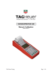
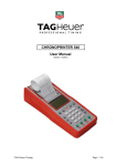
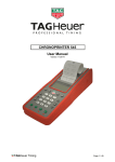
Start clock HL 940 User Manual Version 06/2011 Table of contents 1. 2. 3. 4. 5. 6. 7. 8. 9. 10. 11. 12. 13. 14. 15. 16. 17. 18. 19. 20. Global Start Clock Description 2.1. Programming Keyboard 2.2. Back Side of the Start Clock Switch ON the Start Clock HL 940 3.1. GPS Synchronization 3.2. Manual Synchronization Menu Features Open / Close a run (Menu 0_) Synchro (Menu 1) 6.1. Manual Synchro (Menu 10) 6.2. GPS Synchro (Menu 11) Timing Mode (Menu 2) 7.1. PTB Sequential (setting “00”) 7.2. SPLIT: (setting “01”) Start Clock Program (Menu 3) 8.1. Recall a program (Menu 30) 8.2. Modify a program (Menu 31) 8.2.1. Intervals (Blue blinking disc) 8.2.2. Inversion Red / Green (Red/Green blinking disc) 8.2.3. Count Down (Cyan blinking disc) 8.2.4. Red Zone (Red blinking disc) 8.2.5. Yellow Zone (Yellow blinking disc) 8.2.6. Green Zone (green blinking disc) 8.2.7. Warning Beep (Yellow blinking disc) 8.2.8. Beep ON (Blue blinking disc) 8.2.9. Beep Duration (Green blinking disc) 8.2.10. Start Switch (orange blinking disc) 8.2.11. Pause Switch (violet blinking disc) 8.3. Save a program (Menu 32) Parameters (Menu 4) 9.1. Precision (Menu 40) 9.2. Lock Time (Menu 41) 9.3. Numbering (Menu 42) 9.4. Input Status (Menu 43) 9.5. Sound Level and LED brightness (Menu 44) 9.6. RS232 Baud Rate (Menu 45) 9.7. AUX1 RS232 (Menu 46) 9.8. AUX2 RS232 (Menu 47) 9.9. Display Mode (Menu 48) 9.10. Language (Menu 49) Other (Menu 5) 10.1. Download a Run (Menu 50) 10.2. Status (Menu 51) 10.3. Clear Memory (Menu 52) Extension Modules (Menus 6, 7, 8) 11.1. Ethernet module: 11.2. GSM module: Quick Start a Run RS232 and Ethernet Protocol Battery Charging Download a new version of Software and/or language GPRS Data transmission (Module available in Option) Connector Pin Out Technical Specification Configurations 19.1. Start Clock and Mintimer synchronized 19.2. Start Clock and Matrix Display Start Clock Manager HL940 3 4 4 5 6 6 6 7 9 10 10 10 11 11 11 12 12 12 13 13 13 13 13 14 14 14 14 14 14 15 16 16 16 16 16 17 17 17 17 17 17 18 18 18 18 19 19 19 19 20 21 22 23 23 24 25 25 26 27 2 1. Global Nothing less than the most high-performance start device ever conceived, the new HL940 TAG Heuer Start Clock represents a breakthrough in the timing world , combining an unique analogical dial and LED full colour display design to give unparalleled precision and practicality in the pure avant-garde tradition of TAG Heuer. This new and unique architecture, inspired from the well-known TAG Heuer original start clock, the undisputed leading timing device in the rally car racing , introduces a new generation of Start devices, free of any constraint and displaying timing data and information in the most logical and elegantly way possible. Its many innovative features include: GPS antenna integrated Outdoor LED 2 digit display for Count Down (120mm high) Outdoor LED in 3 colors for seconds display Outdoor LED in 3 colors (up to 64) for the Start Light Two reflective needles to show hours and minutes in classic analog fashion Internal high-volume horn Two timing modes available: Precision Time Base with sequential numbering, and Split mode with bib number. Up to 50 different programs for the start process Easily accessed side control panel Two input channels for external switching device (photocells, start gate or other normally-open devices Three bidirectional RS232 / RS485 data ports (PC / AUX 1 / AUX 2) for PC, external printer (HL 200), Display etc. One Input for “Start / Stop / Restart” function One output “Top Minute,” output impulse to synchronize with other timing devices One output “Top Synchro” output impulse at the precise time of start External plug for GPS External Jack plug for additional horn Three expansion slots for ethernet connection, GPRS, etc Standard communication protocol “THCOM-08” Compliant with all M-sports Timing Software Important! Don’t forget to register your product online at: http://www.tagheuer-timing.com/tools/product-register 3 2. Start Clock Description 2.1. Programming Keyboard This keyboard is on the right side of the Start Clock. It allows you to configure the Start Clock for your specific application 1 1 Power ON/OFF switch 2 Power Status LED F Menu – To enter or to exit the menu and sub-menus ▲ ▼ UP and DOWN keys to explore the menu ◄┘ ENTER – to confirm menu selection. ►I I Function Start / Stop / Reset for the departure program 2 4 2.2. Back Side of the Start Clock 11 12 13 1 1 2 3 4 5 6 7 8 9 10 11 12 13 14 15 16 17 2 3 14 4 15 5 6 16 17 7 8 9 10 High Speaker Horn Backup battery – 2 battery type AA Fuse 5 A Input 1 and Input 2 (photocells, start gate or other devices) Input Start / Stop / Reset – for departure program Top Minute Synchro Top Chrono Synchro Power Supply Plug (15VDC – 4.6 A) Tripod screw fixation Options Slots 1, 2 and 3 (Ethernet, GPRS, etc.) Status LED Jack plug for external speaker horn GPS LED and plug for External GPS Sub-D 9P for PC Sub-D 9P for AUX 1 Sub-D 9P for AUX 2 Battery charge status LED 5 3. Switch ON the Start Clock HL 940 3.1. GPS Synchronization 1) Switch ON the HL 940, the 2 needles will automatically be at 0. 2) The 2 Digit Display will show “0” or come back directly to the last GMT time set. The Start Clock will try to synchronize itself to the GPS signal using its internal GPS antenna. With the arrows ▲ / ▼ you can change the difference time between GMT time, and your time zone. The first digit will indicate the number of hours, and the second digit (0 or 3) will indicate 0 or 30 minutes. Example: -2h30 from GMT “-23” At any time, you are allowed to press and hold for 5 seconds the Start / Stop / Reset button and you will automatically go to the manual setting of time of the day (menu 10). 3) To validate your time zone, press “◄┘” (Enter) 4) The “+/-“ symbols will alternate, indicating that the system is searching the GPS signal 5) The 2 Digit Display will indicate how many satellites are found. 6) As soon as the HL 940 has found more than 4 GPS signals, it will automatically set the time (needle) and wait for the Top Minute signal from the satellite. Important On the bottom of the Start Clock you find a LED near the GPS Plug. ► When this LED is blinking: gives the number of Satellites found ► When the LED is ON: Start clock searching Satellites It is possible to select the GPS internal or external with the (▲ / ▼) arrows ► External GPS: sign « + » blinking ► Internal GPS: sign « - » blinking 3.2. Manual Synchronization In case you wish to configure the time manually, proceed as follows: 1) Switch the unit ON. The 2 needles will automatically be at 0 2) Press and hold for at least 5 seconds the ”►II” button on the side panel (Start / Stop / Reset) 3) Using the (▲ / ▼) arrows, select the Hours then Minutes (validate each value with “◄┘”) 4) Using the (▲ / ▼) arrows, select the Date, Day, Month and Year (validate each value with “◄┘”) 5) Give an impulse to either input 1 or 2 with a manual push button (HL 18) This procedure allows you to synchronize different timing devices together such as CP 540, Minitimer. Important The start clock sends a “TOP MINUTE” impulse through the yellow/black banana jacks. This impulse may be used with any other timings devices for synchronization. 6 4. Menu Features The menu is accessible with the keypad on the right side of the Start Clock. The 2 Digit Display provides the menu status The menus are at 2 levels: Left Digit: Level 1 Right Digit: Level 2 Once the desired menu level is selected, you will have the possibility to change settings. The LED Start Light informs you on which of the menu / settings you are at. To access to the Menu, press the function “F” key At anytime, it is possible to escape (without saving) from the current menu level, by pressing “F.” If you see the hyphen sign “ - “ on the 2 Digit Display, this indicates that you that a run is in progress. If a run is in progress, several menu options will not available, such as Clear Memory, Timing Mode etc. Menu Description LED Start Light 0_ Open / Close a session White 1_ Synchro White 10 Manuel (Set GPS OFF) White 11 2_ Hours Red Minutes Yellow Days Orange Month Blue Year Purple GPS White (set GPS On + time zone) Blinking Timing Mode White 0 = PTB Sequential Blinking 1= Split Blinking Available for the Run Menu X 3_ Program White X 30 Call a Program White X Program number 1 to 50 31 Values modifications Blinking White - Intervalle Blinking Blue - Reverse Colour R/G Blinking Red/Green - Countdown Blinking Cyan - Red zone Blinking Red - Yellow zone Blinking Yellow X 7 32 - Green zone Blinking Green - Single Beep Blinking Yellow - Beep ON Blinking Bleu - Beep duration Blinking Green - Start switch (0, 15, 30, 60) Blinking Orange - Pause Switch (0, 1) Blinking Violet Save all setups into a program: White Program number (10 to 49) Blinking White 4_ Parameters 40 Precision Setting 0 – 5 41 Locking Time X X White X Blinking white White X White X Setting 10 – 14 (20 – 24) 42 Numbering Setting 10 – 11 (20 – 21) 43 Input Status (input 1 and 2) White 0=OUT / 1 = IN / 2 = Blocked 44 45 46 Sound level and led brightness Volume (0-2) Blinking white Display Brightness Blinking Blue Dial Brightness Blinking Purple PC RS232 Baud Rate Setting : Setting: 0 – 5 White AUX1 RS232 White Setting : 0 – 2 47 AUX2 RS232 Setting: 0 48 White Display Mode X X Blinking white X Blinking white White X Blinking white White X Blinking white 49 Language Setting: 1 – 3 5_ Other Function 50 Download a run White Blanking white White Target Blinking white N° Run Blinking Blue 51 Status White 52 Clear Memory White YES / NO X X X Blinking white 6_ Extension Modus 1 * White X 7_ Extension Modus 2 * White X 8_ Extension Modus 3 * White X * please refer to the chapter Option N° 11 8 5. Open / Close a run (Menu 0_) The Start Clock HL 940 is a complete timing system. It is possible to open a run, as with other TAG Heuer Timing devices (Chronoprinter 540 or Minitimer HL 440). All times will be recorded and memorized once a Run is opened. Open a new run: Select the menu “0_” with the “F” button, and validate the selection with “◄┘” (Enter) Automatically a new run is open (N° of the Run will be printed) The run number is displayed on the 2 Digit Display for 5 seconds. To Close a run: Select from the menu “- 0_” with the “F” button and valid with “◄┘” (Enter) The 2 Digit Display will show “_ _” Validate your choice by pressing the (▲) arrow. The display will show “ ” Validate your choice with “◄┘” (Enter) If the Start Clock is connected to a serial printer (HL 200) on AUX 1, you will have the following information printed: Open a RUN Close a RUN PTB SEQUENTIAL RUN Nr. 02 ********************************** PRECISION 1/100 SEC MEMORY FREE 25000 DATE <DMY> 19/11/10 TIME <HM> 11:44:35 RUN Nr. 02 CLOSED 9 6. Synchro (Menu 1) Synchronizing to a new time-of-day (it is possible to exit this menu anytime with the “F” button). This menu is not available during a Run. 6.1. Manual Synchro (Menu 10) Allows you to enter a new time of the day and date manually, and synchronize the system with a manual input signal (input 1 or Input 2) or with the Start / Stop / Reset button. Once you select “10” from the menu, you will enter: - Hours (RED disk), then confirm with ◄┘ - Minutes (Yellow disk), then confirm with ◄┘ - Day (Orange disk), then confirm with ◄┘ - Month (Blue disk), then confirm with ◄┘ - Year (Purple disk), then confirm with ◄┘ - Synchronise the start clock through either external input (1 – 2) or press the ”Start / Stop / Reset” button Important : The date (day, month and year) is important information, especially when linking your start clock with other timing devices (Chronoprinter 540 or Minitimer 440). If doing so, the Time of the day and Date must be identical between devices! 6.2. GPS Synchro (Menu 11) The Start Clock HL 940 has its own integrated GPS antenna. If the signal of the GPS is not strong enough, you have to connect the external GPS Antenna. Once from the menu “11” is selected: - The 2 needles will be placed automatically at 12:00 - On the 2 Digit Display you will see “+/-“ symbols switching alternately - The number showing on the display tells you how many satellites the HL 940 has found - As soon the HL 940 is able to determinate the time and date, the needle will be placed in the correct position, awaiting the Top Minute signal from the satellite Important : It is possible to escape from this menu at anytime, by pressing and holding the Start / Stop / Reset button for 5 seconds. If you perform this operation, you will then have to synchronize manually. It is possible to select the GPS internal or external with the (▲ / ▼) arrows ► External GPS: sign « -- » blinking ► Internal GPS: sign « + » blinking PLEASE NOTE: UTC TIME The time provided by the satellites is GPS (terrestrial hours) of a certain number of seconds (15 seconds since January 2009). This information is transmitted by satellites every 12,5 mins. It remains in the GPS almanac, this allows fast synchronization. 10 7. Timing Mode (Menu 2) The Start Clock has 2 Timing Modes - Select menu “2_” and validated with ◄┘: - The 2 Digit Display will show you the actual setting (00 or 01) - Using the arrow keys, select your timing mode This menu is not available during a Run 7.1. PTB Sequential (setting “00”) Sequential recording of time-of-Day on 2 channels This mode does not calculate Net Times. In this mode, bib number entry is not possible. 7.2. SPLIT: (setting “01”) Sequential recording of time-of-Day on 2 channels and allows you to enter bib number. This mode does not calculate Net Times. In SPLIT Mode, you have the possibility to connect an External Keyboard (Ref: HL 650-20) on the AUX 1 (selection of the target = PC). Hence you will be able to introduce the bib number. If the start clock is running with a program, you can assign the bib number with the correct time. Between Count Down sequences, the 2 Digit Display will show the bib number. Check carefully the Numbering setting (Manual or Automatic), chapter 9.3 It is not necessary to run a program to display the bib’s number. But you have to be into a Run to see this bib number. 11 8. Start Clock Program (Menu 3) This part of the menu allows you to program the specific configuration for departure intervals, count downs, Red, Yellow, Green, and beep sequence. The Start Clock HL 940 can save up to 50 program banks. Programs 1 to 9 are pre-defined by TAG Heuer Timing (is it not possible to save a different program on those banks). TAG Heuer Timing Standard configurations: Bank 1 2 3 4 5 6 7 8 9 Description Alpine Ski Alpine Ski OK Cross Country Ski Rally 2 min NC FITA NC Start on Demand Pacer 5 sec Inter. Inv R/G Zone Rouge Zone Jaune Zone Verte Start Bip Bip ON Bip OFF Switch Start 0 0 0 0 Compte A rebours 30 15 30 30 60 30 60 120 5 5 3 20 -10 -10 -3 -5 -5 -5 -3 0 -10 -10 -10 -10 -5 -5 -5 -5 0 0 0 0 60 15 60 60 0 1 240 0 -30 0 -30 -10 0 60 0 5 0 0 5 5 1 0 -5 -5 0 0 -5 -5 -5 -5 0 0 0 15 The bank selected is automatically copied into “0”. You are allowed to make modifications to any parameters to meet your requirements. The bank “0” will be used during the race. You may save your personal parameters to banks 10 to 49. Warning : If you do not save your parameters, you will lose your settings when the unit is turned OFF. You are strongly recommended to save your parameters and keep a log book of those functions. 8.1. Recall a program (Menu 30) Menu selection “31” allows you to recall a program. The setting (white blanking disc) informs you that you can select a program bank. Only non-empty bank are available. As soon it is selected, all the parameters are coping into the bank “0”, and you will be able to modify them. 8.2. Modify a program (Menu 31) The ideal time is always referred by the second “0” of the Display. The setting is shown in two ways o All settings from 0 to 59 sec: displayed on the LED Dial and on the 2 Digit Display o All settings greater than 1 minute: the 2 Digit Display shows number of Minute and the LED Dial shows the number of seconds 12 8.2.1. Intervals (Blue blinking disc) Time between two Starts From 0 to 3600 sec (60 minutes) Picture show: 1 on the Digit + 15 Sec = 1 mins + 15 sec Warning: If the Interval is smaller than the countdown and Red zone sequence, the next sequence will start immediately after the prior start. Important: If you select 0 value, the start clock will count down only once. 8.2.2. Inversion Red / Green (Red/Green blinking disc) Setting 0 = Red / 1 = Green. This setting will change the colors of the LED Dial just like the LED Start Light. For a valid count down (setting: 0=Red): the competitor is not allowed to start during the count down (Red). The beep and Green LED will give the authorization to start. For an “Allowed Start Window” (setting: 1=Green), the competitor is allowed to start during selected time. It is useful for a race where the competitor has a certain time window to start the race (FITA, X-Trial etc). 8.2.3. Count Down (Cyan blinking disc) Count down for each competitor (or allowed time) From 0 to 3600 sec (60 minutes) The 2 Digit Display will show seconds (from 0 to 60) then minutes Warning: If the Interval is smaller than the countdown sequence, the next sequence will start immediately after the prior start. 8.2.4. Red Zone (Red blinking disc) This sets the allowed start time window after Zero or GO, then the LED becomes RED From 0 to 30 sec Example If you set the value to 0: at the zero start time, the Start Light will switch to RED. If you set this value to +20 sec (for rally), the last color set (in this case, green) will show up to +20 seconds after the zero start time. 8.2.5. Yellow Zone (Yellow blinking disc) This is the warning zone during the Count Down and approaching zero start time (GO!). During this zone, the Start Light is Yellow, same as the LED seconds dial. From – 1 to – 30 sec 13 8.2.6. Green Zone (green blinking disc) This sets the green zone where a start is allowed During this zone, the Start Light displays in Green, same as the LED seconds dial. From 0 to – 30 sec (or maximum yellow zone) 8.2.7. Warning Beep (Yellow blinking disc) Range: from – 30 to 0 This is the first Beep made by the Start Clock to bring the athlete to attention. It is normally set at the beginning of the yellow zone. The LED Seconds Dial will blink to show you the position, same as on the 2 Digit Display 8.2.8. Beep ON (Blue blinking disc) Range: from Single Beep to Red Zone This is the beginning of the countdown sequence. The LED Seconds Dial will blink to show you the position, same as the 2 Digit Display 8.2.9. Beep Duration (Green blinking disc) Range: from Beep ON to Red Zone This is the Beep sequence just before GO or zero (start time). The last beep is a higher tone frequency. The LED Seconds Dial will blink to show you the position, same as the 2 Digit Display 8.2.10. Start Switch (orange blinking disc) Setting: 0, 15, 30, or 60 This setting will define the start sequence of the first count down. Set = 0 Count down programmed to start at the next second after pressing the Start / Stop / Reset button. Set = 15 Count down programmed to start at the next quarter after pressing the Start / Stop / Reset button. Example: press the S/S/R button at 12 sec: the count down will start at 15 sec Set = 30 Count down programmed to start at the next half after pressing the button Start / Stop / Reset button. Example: press the S/S/R button at 12 sec: the count down will start at 30 sec Set = 60 Count down programmed to start at the next minute after pressing the Start / Stop / Reset button. Example: press the S/S/R button at 12 sec: the count down will start at 60 sec 8.2.11. Pause Switch (violet blinking disc) Setting: 0 or 1 This allows you to pause the countdown program using the Start / Stop / Reset button. Set = 0 Disable the Count Down pause function Set = 1 Enable the Count Down pause function The countdown sequence will pause until you press the Start / Stop / Reset button again. The LED Seconds Dial will switch OFF and display only the Time. The 2 Digit Display will show the rest of the count down. Important : If at any time, you press and hold the “Start/Stop/Reset” button for more that 5 seconds, you will completely reset the start sequence. 14 8.3. Save a program (Menu 32) This menu allows you to save your program parameters (bank 0) to another bank. Only the personals banks (10 to 49) are available to save your program setting. Please note: It is possible to save your new configuration to an existing bank. 15 9. Parameters (Menu 4) 9.1. Precision (Menu 40) You can choose the timing precision between 1 seconds to 1/100’000th of second. Setting = 0 Precision = 1 sec Setting = 1 Precision = 1/10 sec Setting = 2 Precision = 1/100 sec Setting = 3 Precision = 1/1’000 sec Setting = 4 Precision = 1/10’000 sec Setting = 5 Precision = 1/100’000 sec 9.2. Lock Time (Menu 41) Lock-out time of the 2 inputs is selectable from 0.01, 0.1, 1 and 10 sec Select menu 41, and validate with ◄┘ Select which input you want to use (left digit), validate with ◄┘ Select the setting for this Input (0 to 4) on the right digit, validate with ◄┘ BLOCKED LOCK TIME = 0.01 sec LOCK TIME = 0.1 sec LOCK TIME = 1 sec LOCK TIME = 10 sec Input 1 Setting = 10 Setting = 11 Setting = 12 Setting = 13 Setting = 14 Input 2 Setting = 20 Setting = 21 Setting = 22 Setting = 23 Setting = 24 The minimum lock-out time of 0.01 sec should not be used with any mechanical triggering device (bounce may cause several impulses). 9.3. Numbering (Menu 42) You can select Manual or Automatic competitor numbering assigned to input 1 or input 2: Automatic: in ascending order (UP) Manual: enter the competitor numbers manually During a Run, the 2 Digit Display will show “– –“ to indicate that you may now enter a bib number. Enter bib numbers via Keypad (HL 650-20) or using the UP/DN arrow keys. If you have selected automatic numbering, you may change the bib number with the Keypad or arrow keys. Manual Automatic 9.4. Input 1 Setting = 10 Setting = 11 Input 2 Setting = 20 Setting = 21 Input Status (Menu 43) Selection of Inputs and related timing functions (transmit/receive) Use this to select if input signals are in the form of impulses (Photocells, etc) or data transmission from another timing device (CP 540, HL 440) Input 1 is on the left digit Input 2 is on the right digit Setting = 0 Transmit (default parameter) Setting = 1 Receive Setting = ▬ Blocked This menu is not accessible while a RUN is in progress! 16 9.5. Sound Level and LED brightness (Menu 44) You may change the Sound Level (from 0 to 3) and Digit / Start Light intensity (from 0 to 10) , as well as LED Seconds Dial intensity (from 0 to 10) Select menu 44 Blinking White: Select the sound level (from 0 to 3) Blinking Blue: Select the 2 Digit Display / LED Start Light brightness (from 0 to 10) Blinking Purple: Select the LED Seconds Dial brightness (from 0 to 10) 9.6. RS232 Baud Rate (Menu 45) The RS232 port is use mainly for interface to a PC. By default, the baud rate is set to 38400 dbs to allow the HL 940 Remote Control software to access all the parameters. For Timing Software, this port is normally set at 9600 bds. Setting = 0 2400 Bds Setting = 1 9600 Bds Setting = 2 9600 Bds with Ctrt Flow Setting = 3 38400 Bds Setting = 4 57600 Bds Flow control: If any equipment connected to the RS232 port does not allow a flow minimum of 2400 dbs (ex. Radio transmission), a basic flow control is available. Once this option is activated, the HL 940 sends the first frame and waits to receive the characters 0x06 « ACK » before sending the next one. 9.7. AUX1 RS232 (Menu 46) The AUX Port may be used as follows: Setting = 0 Serial Printer (HL 200) Setting = 1 RS232 at 9600 Bds Setting = 2 RS232 at 9600 Bds Ctrl Flow Setting = 3 RS232 at 38400 Bds 9.8. AUX2 RS232 (Menu 47) Mainly used for Display communication (HL970) Setting = 0 HL970/980 (9600 Bds) This setting is today blocked at 0 and could be not change. 9.9. Display Mode (Menu 48) Display mode (refer to the Port AUX2 Setting = 1 Time of the day Setting = 2 Start Light Setting = 3 Start SPLIT (bib and count down up to 9 min 59 sec) Setting = 4 Start PTB (Count down up to 59 min 59 sec) 9.10. Language (Menu 49) From this menu, you have the possibility to change the print language. Several languages are available: Setting = 0 English Setting = 1 French Setting = 2 German Setting = 3 Italian 17 10. Other (Menu 5) 10.1. Download a Run (Menu 50) You have the possibility to download a run to a printer via RS232, AUX1, or GPRS (optional) Once the Menu 50 is valid, you must select the target device Target (Blinking White) Setting = 0: To Printer Reprint all times memorized in a run. Setting = 1: To PC via RS232 (AUX 1) All times memorized in a run are sent to the PC (download to a Timing Software) Setting = 2: To timing device via RS232 (AUX 1) All memorized times in a run sent to another timing device (CP 540 or HL 440). Setting = 3: To PC via GPRS With this option, it is possible to send all times of a run via GPRS System to a PC Setting = 4: To timing device via GPRS With this option, it is possible to send all times of a run via GPRS to another timing device (Chronoprinter 540 or Minitimer HL 440) Setting = 5: To USB (optional) Save all the times memorized in one run to the USB memory key Then select the run you want to upload (Blinking Blue) 10.2. Status (Menu 51) With this menu choice you will be able to print the general status of the HL 940 settings. 10.3. Clear Memory (Menu 52) Clear the memory only when you start a new timing session and you are sure you do not need to retain the previous session(s) in memory! After you validate from the menu 50, the 2 Digit Display will show “_ _.” Validate your choice by pressing the UP arrow once (display shows “CL”) and confirm with ◄┘ This menu function is not accessible during a Run. 18 11. Extension Modules (Menus 6, 7, 8) You have the possibility to install onto your Start Clock several options, including “Ethernet module” or “GSM Module” WARNING: It is strictly forbidden to remove an option when the Start Clock is powered. IMPORTANT: The Start Clock will not drive to similar option. Each slot corresponds to a menu item Slot 1 = Menu 6 Slot 2 = Menu 7 Slot 3 = Menu 8 11.1. Ethernet module: Set = 0 Ethernet OFF Set = 1 Ethernet ON with Standard IP Address (192.168.1.0xx) You have the possibility to change the last 2 digits with the UP/DN arrows Set = 2 Ethernet ON with pre-programmed IP Address The IP Address can be set via PC with the HL 940 Remote Control program Actif port: 7000, 13500, 13501, 13502 and 13503 11.2. GSM module: You have the possibility to send and received timing information via GPRS The full setting of the communication is configured by the GPRS program (IP Address, Port, etc). Set = 0 GSM OFF Set = 1 GSM ON with setting N°1 Set = 2 GSM ON with setting N°2 Set = 3 Status: will print the status information Set = 4 SIM Card sold 12. Quick Start a Run To start a Run, you must follow this procedure: The HL 940 must first be synchronized (by GPS or manually) to time-of-day and date. In case of several timing devices running simultaneously, you should take care that all timing devices are synchronized together (Manual Synchro or Top Minute Synchro) Select the program you want to run. 19 You can select one of the TAG Heuer Timing programs (bank 1 to 9), or your personal program. At any time you are allow to change your settings and save them. Open a run (Menu 0_) If you do not open a run, you can still have all times printed (if printer is connected) and all times sent by RS232 to your PC, but none of times will be memorized by the start clock. As soon you switch the Start Clock off, the times will be erased from memory. Start the Program. A program is not needed to record and memorize times. It is used only for a Start Sequence. 13. RS232 and Ethernet Protocol For details of the communication protocol, please refer to the document: THCOM08. Please contact us directly at : [email protected] 20 14. Battery Charging Each Start Clock has a Lithium-Polymer battery with a capacity of 10 Ah. For charging the battery, we suggest that you to use our TAG Heuer charger. Using another model other than the TAG Heuer charger may damage the device. o To charge the internal battery, turn off the system. o Connect the charger to the AC source o Plug the charger into the device o The red LED will be on while charging IMPORTANT: Always charge the device at a temperature between 32°F (0°C) and 86°F (30°C) FOR YOUR SAFETY Batteries will not explode or be a fire HAZARD as a result of excessive charge or discharge or if a battery is installed with incorrect polarity. Opening a Start Clock and changing the battery by a non-authorized person is strictly forbidden and will void the warranty! The red LED is on during the charging process, when fully charged, the red LED shuts down and the green LED will turn on. It takes approximately 5 hours fully charge a completely discharged battery. Never connect the terminals of the battery in short-circuit. Avoid keeping the battery pack fully charged or completely discharged for a long period. Doing so reduces the lifespan of the battery. In the case of prolonged non-utilization of the battery pack, it is necessary keep the system in a dry room, and at room temperature. 21 15. Download a new version of Software and/or language Program downloads and new releases of HL 940 software are available Free of Charge on our website www.tagheuer-timing.com For this operation, you need to have: RS232 cable PC with output RS232 (Sub-D9p) The software « CP540 Firmware.exe » Procedure 1. Copy the software «CP540 Firmware.exe » onto your hard disk 2. Power the HL 940 with an external power supply (The HL 940 is off). 3. Connect the RS232 cable 4. Run the software « CP540 Firmware.exe » Select Serial Port Select File Name 5. 6. 7. 8. Select the COM Port Select the file: Update (HL940_xxx.dat) Press START on the software. Power ON the HL940 (press the ON button for 5 seconds) The HL 940 will go into a special mode « Download ». The LDC back light will be ON, but LCD will be blank. 9. As soon as the upgrade is downloaded into the HL 940, validate the software with OK. 10. Remove the RS232 cable from the HL 940, and switch on the HL 940 again. 11. The new software version will be printed (if the Printer is in ON) 22 16. GPRS Data transmission (Module available in Option) Download this software from our Homepage: www.tagheuer-timing.com Provide all of the requested information and upload the setting on your Start Clock in order to transmit all data over your Mobile broadband provider. Print current settings (will only work if a printer is connected). The SIM Balance is the Dial up number in order to get the remaining available credit on your prepaid SIM card (Top Up). 17. Connector Pin Out PC (DB9/F),J11 ****************** 1 - RS485 TX Y 2 - RS232 TX 3 - RS232 RX 4 - RS485 RX B 5 - GROUND 6 - RS485 TX Z 7 - NC 8 - RS485 RX A 9 - NC AUX1 (DB9/F),J13 ********************* 1 - NC 2 - RS232 TX 3 - RS232 RX 4 - NC 5 - GROUND 6 - NC 7 - NC 8 - PRINTER_READY 9 - SYNC OUT AUX2 (DB9/F),J12 ********************* 1 - NC 2 - RS232 TX 3 - RS232 RX 4 - NC 5 - GROUND 6 - NC 7 - NC 8 - NC 9 - SYNC OUT 23 18. Technical Specification General o o o o o o Autonomy (at +68°F / 20°C) Normal use temperature Charging temperature Size Weight : Power supply : Lithium-Polymer Battery o Type o Charging current Charger HL 940 o Primary o Secondary Warranty: ???? hours between - 4°F (-20°C) and +131°F (+55°C) between +32°F (0°C) and +86°F (+30°C) ???? 10 Kg 15 V DC 4.5 A 11.1V Li-Po 10Ah 2A minimum (~ 5-6 hours) 110 / 230V – 50/60Hz 15V – 4.5A TWO years after delivery. The warranty is null and void under the following conditions: - The battery is out of order - Poor maintenance and obvious physical damage - Input or Outputs damaged by poor connection - The device was opened without factory authorization The Start Clock HL 940 package include: - 1 Plastic case 1 Start Clock 1 External GPS antenna 1 Charger 110-240 VAC / 15VDC 1 User manual HL 605-10? 24 19. Configurations 19.1. Start Clock and Mintimer synchronized Setting HL 940 RS232 AUX1 = 9600 dBs (N° 46 = 2) Setting HL 440 RS232 PRINTER = Printer Synchro: Slave Timing Mode: Split 5-8 or PTB 5-8 RS232 M/M 2–3/3–2/5–5 Synchro 9 – 9 HL 200 25 19.2. Start Clock and Matrix Display 26 20. Start Clock Manager HL940 This Interface allows you to manage all the functions on the HL 940 Start Clock. It is also possible to use this software to set your parameters offline. During a race, you will be able to simulate an impulse (manual input) and simulate on the Start Clock Manager exactly what will be displayed on your HL 940 27 TAG Heuer PROFESSIONAL TIMING 6A Louis-Joseph Chevrolet 2300 la Chaux-de-Fonds Switzerland Tel : 032 919 8000 Fax : 032 919 9026 E-mail: [email protected] Http: //www.tagheuer-timing.comm 28