1
4.0 INSTA L L AT I O N
The Model 2017A is simple to install. After configuring the
DCE/DTE and active/passive switches, connect the two twisted pairs
using the following instructions.
4.1
TWISTED PAIR WIRING OVERVIEW
Only one Model 2017A is needed for each RS-232 to 20mA current loop circuit. The Model 2017A is connected to the current loop
device using two twisted pairs. The pairs must be dry, unconditioned
metallic wire, 19-26 AWG. Best distance is achieved with smaller
gauges (i.e., thicker wires). When you have completed wiring for your
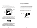
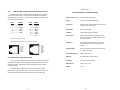
data circuit, the pin connections should be as shown below:
XMT
XMT
G
RCV
RCV
4.1.1
+
To Shield (Optional)
+
RCV+
RCV G
XMT XMT +
}
One Pair
}
One Pair
TWISTED PAIR CONNECTION USING TERMINAL BLOCKS
Once the unit has been opened, you will be able to see the terminal blocks located at the rear of the PC board.
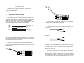
2. Strip the outer insulation from the twisted pairs about one inch
from the end.
3. Strip back the insulation on each of the 2 twisted pair wires
about .25".
The terminal block/strain relief version of the Model 2017A allows
you to hook up the line side interface using bare wires. The following
instructions will tell you how to open the case, connect the bare wires,
and fasten the strain relief collar in place.
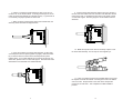
1. Open the unit by gently inserting a screw driver between the
DB-25 connector and the lip of the plastic case (see below). You don't
have to worry about breaking the plastic, but be careful not to bend the
D-sub connector.
4. Connect one pair of wires in the telephone cable to "XMT"
(Transmit) on the terminal block, being careful to observe the polarity.
(The wire connected to "XMT+" must be connected at the other end of
the telephone line to "RCV+" in the other unit and the wire connected
to "XMT-" must be connected at the other end of the telephone line to
"RCV-" in the other unit).
5. Connect the other pair of wires in the telephone cable to "RCV"
(Receive), again being careful to observe the polarity. (The wire connected to "RCV+" must be connected at the other end of the telephone
line to "XMT+" in the other unit and the wire connected to "RCV-" must
be connected at the other end of the telephone line to "XMT-" in the
other unit).
5
6