1
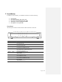
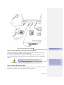
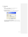
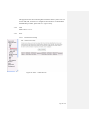
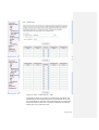
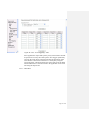
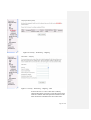
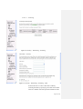
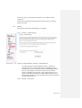
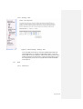
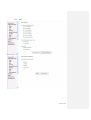
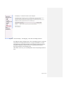
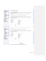
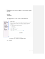
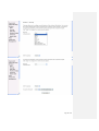
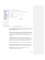
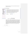
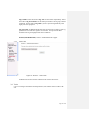
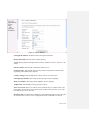
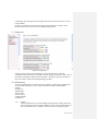
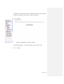
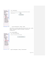
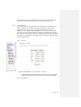
TECOM AH4021
User’s Manual
- MGCP Version -
Copyright © 2004 by TECOM CO., LTD.
Table of Contents
1
INTRODUCTION ..................................................................................................................................................... 4
2
INSTALLATION ....................................................................................................................................................... 5
3
CONFIGURATION .................................................................................................................................................. 9
3.1
SETUP ............................................................................................................................................................... 9
3.2
ESTABLISH THE CONNECTION .......................................................................................................................... 9
3.3
QUICK SETUP ................................................................................................................................................. 11
3.3.1
PPP over Ethernet (PPPoE) Configuration.............................................................................................. 11
3.3.1.1
3.3.1.2
3.3.1.3
3.3.1.4
3.3.1.5
3.3.1.6
3.3.1.7
3.3.2
IP over ATM (IPoA) Configuration........................................................................................................... 16
3.3.2.1
3.3.2.2
3.3.2.3
3.3.2.4
3.3.2.5
3.3.2.6
3.3.2.7
3.3.3
ATM PVC and QoS Configuration ...................................................................................................................18
Connection Type ...............................................................................................................................................18
DHCP Client and WAN Service .......................................................................................................................19
Device Setup .....................................................................................................................................................20
Wireless – Setup ...............................................................................................................................................20
WAN Setup – Summery....................................................................................................................................20
MAC Encapsulation Routing (MER) Configuration ................................................................................. 21
3.3.4.1
3.3.4.2
3.3.4.3
3.3.4.4
3.3.4.5
3.3.4.6
3.3.4.7
3.3.5
ATM PVC and QoS Configuration ...................................................................................................................16
Connection Type ...............................................................................................................................................16
WAN IP Settings ...............................................................................................................................................16
NAT, Firewall, IGMP Multicast and WAN service ...........................................................................................17
Device Setup .....................................................................................................................................................18
Wireless – Setup ...............................................................................................................................................18
WAN Setup – Summary....................................................................................................................................18
Bridge Configuration ................................................................................................................................ 18
3.3.3.1
3.3.3.2
3.3.3.3
3.3.3.4
3.3.3.5
3.3.3.6
3.3.4
ATM PVC and QoS Configuration ................................................................................................................... 11
Connection Type and Encapsulation Mode.......................................................................................................12
PPP Username and Password............................................................................................................................12
IGMP Multicast and WAN service ...................................................................................................................13
Device Setup .....................................................................................................................................................14
Wireless – Setup ...............................................................................................................................................14
WAN Setup – Summery....................................................................................................................................15
ATM PVC and QoS Configuration ...................................................................................................................21
Connection Type ...............................................................................................................................................21
WAN IP Settings ...............................................................................................................................................22
NAT, IGMP Multicast and WAN service ..........................................................................................................23
Device Setup .....................................................................................................................................................23
Wireless – Setup ...............................................................................................................................................23
WAN Setup – Summery....................................................................................................................................23
PPP over ATM (PPPoA) Configuration ................................................................................................... 24
3.3.5.1
3.3.5.2
3.3.5.3
3.3.5.4
3.3.5.5
3.3.5.6
3.3.5.7
ATM PVC Configuration ..................................................................................................................................24
Connection Type ...............................................................................................................................................24
PPP Username and Password............................................................................................................................25
IGMP Multicast and WAN service ...................................................................................................................26
Device Setup .....................................................................................................................................................26
Wireless – Setup ...............................................................................................................................................26
WAN Setup – Summery....................................................................................................................................26
3.4
ADVANCED SETUP .......................................................................................................................................... 26
3.4.1
WAN .......................................................................................................................................................... 27
3.4.2
LAN ........................................................................................................................................................... 28
3.4.3
NAT ........................................................................................................................................................... 28
3.4.3.1
3.4.3.2
3.4.3.3
3.4.4
Security ..................................................................................................................................................... 32
3.4.4.1
3.4.4.2
3.4.5
3.4.6
Virtual Servers Setup ........................................................................................................................................28
Port Triggering Setup........................................................................................................................................30
DMZ Host.........................................................................................................................................................31
IP Filtering ........................................................................................................................................................32
Parental Control ................................................................................................................................................35
Quality of Service...................................................................................................................................... 36
Routing ...................................................................................................................................................... 38
3.4.6.1
3.4.6.2
Routing – Default Gateway ..............................................................................................................................38
Routing – Static Route ......................................................................................................................................38
Page 2 of 69
3.4.6.3
3.4.7
3.4.7.1
3.4.7.2
3.4.8
3.4.9
3.5
3.5.1
3.5.2
3.5.3
3.5.4
3.5.5
3.5.6
3.6
3.7
3.8
3.8.1
4
Backup ..............................................................................................................................................................58
Update ..............................................................................................................................................................58
Restore Default .................................................................................................................................................59
System Log ................................................................................................................................................ 60
SNMP Agent .............................................................................................................................................. 61
Internet Time ............................................................................................................................................. 62
Access Control .......................................................................................................................................... 63
3.8.5.1
3.8.5.2
3.8.5.3
3.8.6
3.8.7
DNS Server .......................................................................................................................................................40
Dynamic DNS ..................................................................................................................................................41
DSL ........................................................................................................................................................... 43
Port Mapping ............................................................................................................................................ 44
WIRELESS ....................................................................................................................................................... 47
Basic ......................................................................................................................................................... 47
Security ..................................................................................................................................................... 47
MAC Filter ................................................................................................................................................ 50
Wireless Bridge ......................................................................................................................................... 52
Advanced................................................................................................................................................... 52
Station Info ................................................................................................................................................ 55
VOICE ............................................................................................................................................................. 55
DIAGNOSTICS ................................................................................................................................................. 57
MANAGEMENT ............................................................................................................................................... 57
Settings ...................................................................................................................................................... 57
3.8.1.1
3.8.1.2
3.8.1.3
3.8.2
3.8.3
3.8.4
3.8.5
Routing – RIP ...................................................................................................................................................40
DNS ........................................................................................................................................................... 40
Services ............................................................................................................................................................63
IP Addresses .....................................................................................................................................................63
Passwords .........................................................................................................................................................64
Update Software........................................................................................................................................ 65
Save/Reboot .............................................................................................................................................. 65
APPENDIX .............................................................................................................................................................. 67
Page 3 of 69
1 Introduction
Congratulations on becoming the owner of the AH4021. Your LAN (local area network) will
now be able to access the Internet using your high-speed ADSL connection. This User Guide
will show you how to install and set up your AH4021.
Features
Internal ADSL modem for high speed internet access
10/100Base-T Ethernet/USB router to provide Internet connectivity to all
computers on your LAN
Support for MGCP protocol
802.11b/g WLAN supported
Network configuration through DHCP
Configuration program you access via an HTML browser
System Requirements
In order to use your AH4021 router, you must have the following:
ADSL service up and running on your telephone line, with at least one public
Internet address for your LAN
One or more computers each containing an USB, Ethernet 10BaseT/100Base-T network interface card or 802.11b/g WLAN card/adapter
For system configuration using the supplied web-based program: a web
browser such as Internet Explorer v5.0 or later, or Netscape v4.7 or later
Page 4 of 69
Commentaire [CT1]: The document
is written with the assumption that an
ISP has provided the product to an
existing customer. However, the text
uses the phrase “your ISP” when
referring the customer to his ISP for
assistance, and when referring to
preconfiguration the ISP has
presumably performed. Search for
instances of “ISP” and substitute the
ISP’s actual name, or rewrite as
needed.
2 Installation
In addition to this document, your AH4021 should arrive with the following:
One AH4021
One power adapter and power cord
One cross-over/straight Ethernet cable
Three RJ-11 to RJ-11 telephone Cable
One splitter or low-pass filter
Front Panel
The front panel contains several LEDs that indicate the status of the unit.
PWR
DSL
LAN1
TEL1
VoIP
ALM
WLAN
LAN2
TEL2
USB
Label
Color
Function
PWR
Green
On: Unit is powered on
Off: Unit is powered off
ALM
Yellow
On: Major alarm occurs.
Off: Unit is functioning well.
DSL
green
Flashes during the training mode.
On: ADSL link is established and active
WLAN
Green
On: Wireless LAN is active
Off: No wireless card or wireless LAN isn’t active
Flashes during data transfer
LAN1-2
Green
On: LAN link established and active
Off: No LAN link
Flashes during data transfer
TEL1-2
Green
On: The telephone is off-hook
Off: The telephone is on-hook
VoIP
Green
On: VoIP link is established and active
Off: VoIP link isn’t established and active
USB
Green
On: USB link is established and active
Off: No USB link
Flashes during data transfer
Page 5 of 69
Rear Panel
The rear panel contains the ports for the unit's data and power connections.
Label
Function
DSL
RJ-11 connector: Connects the device to a telephone jack or splitter using the
supplied cable
USB
USB connector: Connects the device to your PC's USB port, or to your USB hub,
using the cable provided
LAN1-2
RJ-45 connector: Connects the device to your PC's Ethernet port, or to the uplink port
on your LAN's hub, using the cable provided
TEL1-2
RJ-11 connector: Connects the device to your analog phones, using the cable
provided
RESET
Return the configuration to factory default
Power
Connects to the supplied power converter cable
On/Off
Switches the device on and off
Connecting the Hardware
You connect the device to the phone jack, the power outlet, and your computer or network.
WARNING
Before you begin, turn the power off for all devices. These
include your computer(s), your LAN hub/switch (if applicable),
and the AH4021.
Figure 1 illustrates the hardware connections.
The layout of the ports on your device may vary from the layout shown. Refer to the steps
that follow for specific instructions.
Page 6 of 69
Figure 1. Overview of Hardware Connections
Commentaire [CT2]: Edit picture to
match your board’s connectors.
Step 1. Connect the ADSL cable and optional telephone.
Connect one end of the provided phone cable to the port labeled ADSL on the rear panel of
the device. Connect the other end to your wall phone jack.
You can attach a telephone line to the device. This is helpful when the ADSL line uses the
only convenient wall phone jack. If desired, connect the telephone cable to the port labeled
PHONE.
WARNING
Commentaire [CT3]: This warning
assumes that the board contains an
internal filter on the POTS line. If an
external filter is used instead, document
that step here and remove this warning
(with an external filter, the ADSL and
PHONE ports are interchangeable).
Although you use the same type of cable, The ADSL and
PHONE ports are not interchangeable. Do not route the ADSL
connection through the PHONE port.
Step 2. Connect the Ethernet cable.
If you are connecting a LAN to the AH4021, attach one end of a provided Ethernet cable to a
regular hub port and the other to the Ethernet port on the AH4021.
Page 7 of 69
Step 3. Attach the power connector.
Connect the AC power adapter to the PWR connector on the back of the device and plug in
the adapter to a wall outlet or power strip.
Step 4. Turn on the AH4021 and power up your systems.
Press the Power switch on the back panel of the device to the ON position.
Turn on and boot up your computer(s) and any LAN devices such as hubs or switches.
Step 5. Configure the AH4021 through the WEB interface
The detail step3 would be described in Chapter3. It would help you configure the AH4021 to
meet your need.
Step 6. Save the configurations and Reboot.
To make the settings you made on AH4021 take effect.
Page 8 of 69
3 Configuration
3.1 Setup
Step 1: Connect the AH4021 and PC with a straight Ethernet cable.
Step 2: Power on the AH4021.
Step 3: The default IP of the AH4021 is 192.168.1.1.
3.2 Establish The Connection
Enter the IP address (default is 192.168.1.1) of AH4021 from the Web Browser.
A Dialogue Box will be popped up to request the user to login. (Figure 2)
Figure 2. Authentication
Please enter the management username/password into the fields then click on the OK
button (default username/password is admin/admin).
If the authentication passes, the home page “Device Info - Summery” will be displayed
on the browser. (Figure 3)
Page 9 of 69
Figure 3. AH4021 Home Page
Page 10 of 69
3.3 Quick Setup
The system administrator can configure the AH4021 remotely or locally via a Web
Browser. Network configuration need to be planned and decided before starting the
configuration procedure.
Quick Setup allows system administrator to select the appropriate operation mode and
configure the corresponding settings step by step to create a connection.
The following five operation modes are supported:
PPP over Ethernet (PPPoE)
IP over ATM (IPoA)
Bridging
MAC Encapsulation Routing (MER)
PPP over ATM (PPPoA)
3.3.1
PPP over Ethernet (PPPoE) Configuration
Click on “Quick Setup” in the left frame, and follow the steps below to create a
PPP over Ethernet (PPPoE) connection.
3.3.1.1 ATM PVC and QoS Configuration
Figure 4. Quick Setup – ATM PVC and QoS Configuration
Give the VPI/VCI values. Please contact you ISP for the information.
Enable the QoS function for this PVC here. Use Advanced
Setup/Quality of Service to assign priorities for the application.
Click on “Next” to go to next step.
Page 11 of 69
3.3.1.2 Connection Type and Encapsulation Mode
Figure 5. Quick Setup – Connection Type and Encapsulation Mode
Select “PPP over Ethernet (PPPoE)”, and the “Encapsulation Mode”.
Please contact you ISP for the information.
Click on “Next” to go to next step.
3.3.1.3 PPP Username and Password
Page 12 of 69
Figure 6. Quick Setup – PPP Username and Password
Give “PPP Username”, “PPP Password”, and select “Authentication
Method” (AUTO/PAP/CHAP). Please contact you ISP for the
information.
The “Dial On Demand” function, if checked, will tear down the PPP
link automatically if there is no outgoing packet for the programmed
period of time which is set below.
The “PPP IP extension” function, if checked, will assign the IP
address got from the ISP to the internal PC via DHCP. In this mode,
the internal PC will be assigned with a public IP got from PPP, and
AH4021 will act as a bridge between the PC and PPPoE server.
The “Concurrent Bridge” function, if checked, will enable Bridge
service simultaneously while PPPoE is operating. In this mode, other
services such as VoIP/Video can use the Bridge interface. It is useful
when the service provider of Data service is different from VoIP/Video.
When the “Concurrent Bridge” is enabled, AH4021 will activate the
DHCP Client on the Bridge interface. If your ISP requests for DHCP
“Vendor ID” option, please fill in the string in “Option 60”.
AH4021 set up PPPoE connection automatically when there does not
exist the PPPoE connection in it and user wants to send traffic to ISP
The users is able to assign some specific ATM PVC(s) to run PPPoE,
when AH4021 is with multiple ATM PVC connection
Click on “Next” to go to next step.
3.3.1.4 IGMP Multicast and WAN service
Figure 7. Quick Setup – IGMP Multicast and WAN service
Check to Enable/Disable IGMP Multicast and WAN Service.
Page 13 of 69
Click on “Next” to go to next step.
3.3.1.5 Device Setup
Figure 8. Quick Setup – Device Setup
Give IP (LAN IP) and Subnet Mask to the device.
Select to Disable/Enable DHCP Server and configure related settings
for that mode.
If necessary, check the “Secondary IP” to configure the secondary IP
address and Subnet Mask for LAN. This IP address is used for
management only.
Note that Network Address Translation function (NAT) is default
enabled and is not showing on the page to prevent it from being
disabled.
Click on “Next” to go to next step.
3.3.1.6 Wireless – Setup
Page 14 of 69
Figure 9. Quick Setup – Wireless – Setup
Enable the WiFi function here and configure the SSID for the WiFi
interface.
3.3.1.7 WAN Setup – Summery
Figure 10. Quick Setup – WAN Setup – Summary
The last page gives a summary of previous steps. Make sure that the
Page 15 of 69
settings match the settings provided by ISP, and then click on
“Save/Reboot” button to complete the configuration procedure.
3.3.2
IP over ATM (IPoA) Configuration
Click on “Quick Setup” in the left frame, and follow the steps below to create
an IP over ATM (IPoA) connection.
3.3.2.1 ATM PVC and QoS Configuration
Please refer to 3.3.1.1
3.3.2.2 Connection Type
Figure 11. Quick Setup – Connection Type and Encapsulation Mode
Select “IP over ATM (IPoA)”, and the “Encapsulation Mode”. Please
contact you ISP for the information.
Click on “Next” to go to next step.
3.3.2.3 WAN IP Settings
Page 16 of 69
Figure 12. Quick Setup– WAN IP Settings
WAN IP/Subnet Mask, default gateway, and DNS server settings.
Please contact you ISP for the information.
Click on “Next” to go to next step.
3.3.2.4 NAT, Firewall, IGMP Multicast and WAN service
Figure 13. Quick Setup – IPoA – NAT, Firewall, IGMP Multicast and WAN service
Page 17 of 69
Check to Enable/Disable NAT and Firewall functions.
Use Advanced Setup/Security to assign filter rules. Check to
Enable/Disable IGMP Multicast and WAN Service.
Click on “Next” to go to next step.
3.3.2.5 Device Setup
Please refer to 3.3.1.5.
3.3.2.6 Wireless – Setup
Please refer to 3.3.1.6
3.3.2.7 WAN Setup – Summary
Figure 14 Quick Setup – WAN Setup – Summary
The last page gives a summary of previous steps. Make sure that the
settings match the settings provided by ISP, and then click on
“Save/Reboot” button to complete the configuration procedure.
3.3.3
Bridge Configuration
Click on “Quick Setup” in the left frame, and follow the steps below to create a
Bridging connection.
3.3.3.1 ATM PVC and QoS Configuration
Please refer to 3.3.1.1.
3.3.3.2 Connection Type
Page 18 of 69
Figure 15. Quick Setup – Connection Type and Encapsulation Mode
Select “Bridging”, and the “Encapsulation Mode”. Please contact you
ISP for the information.
Click on “Next” to go to next step.
3.3.3.3 DHCP Client and WAN Service
Figure 16. Quick Setup – DHCP Client and WAN Service
Page 19 of 69
Give a service name and check the box to enable this wan service.
If DHCP Client is requested, check the box and fill in the optional
“Vendor ID” in “Option 60” box.
The IP address got from DHCP Client will be on WAN side.
Click on “Next” to go to next step.
3.3.3.4 Device Setup
Figure 17. Quick Setup – Device Setup
Give LAN IP and Subnet Mask.
Click on “Next” to go to next step.
3.3.3.5 Wireless – Setup
Please refer to 3.3.1.6
3.3.3.6 WAN Setup – Summery
Page 20 of 69
Figure 18 Quick Setup – WAN Setup – Summary
The last page gives a summary of previous steps. Make sure that the
settings match the settings provided by ISP, and then click on
“Save/Reboot” button to complete the configuration procedure.
3.3.4
MAC Encapsulation Routing (MER) Configuration
Click on “Quick Setup” in the left frame, and follow the steps below to create a
MAC Encapsulation Routing (MER) connection.
3.3.4.1 ATM PVC and QoS Configuration
Please refer to 3.3.1.1.
3.3.4.2 Connection Type
Page 21 of 69
Figure 19. Quick Setup – Connection Type and Encapsulation Mode
Select “MAC Encapsulation Routing (MER)”, and the “Encapsulation
Mode”. Please contact you ISP for the information.
Click on “Next” to go to next step.
3.3.4.3 WAN IP Settings
Page 22 of 69
Figure 20. Quick Setup – WAN IP Settings
WAN IP/Subnet Mask, Default Gateway, and DNS Server can either
be obtained automatically or set manually.
The WAN IP can be either fixed (assigned by your ISP) or dynamic
(via DHCP Client). Enter the “Vendor ID” if DHCP Client is selected
and your ISP requests for it.
Click on “Next” to go to next step.
3.3.4.4 NAT, IGMP Multicast and WAN service
Please refer to 3.3.2.4.
3.3.4.5 Device Setup
Please refer to 3.3.1.5.
3.3.4.6 Wireless – Setup
Please refer to 3.3.1.6.
3.3.4.7 WAN Setup – Summery
Page 23 of 69
Figure 21. Quick Setup – WAN Setup – Summary
The last page gives a summary of previous steps. Make sure that the
settings match the settings provided by ISP, and then click on
“Save/Reboot” button to complete the configuration procedure
3.3.5
PPP over ATM (PPPoA) Configuration
Click on “Quick Setup” in the left frame, and follow the steps below to create a
PPP over ATM (PPPoA) connection. The following setting steps are all the
same as PPP over ATM (PPPoE) steps.
3.3.5.1 ATM PVC Configuration
Give the VPI/VCI values. Please refer to 3.3.1.1.
3.3.5.2 Connection Type
Page 24 of 69
Figure 22. Quick Setup – Connection Type and Encapsulation Mode
Please refer to 3.3.1.2
3.3.5.3 PPP Username and Password
Figure 23. Quick Setup – PPP Username and Password
Give “PPP Username”, “PPP Password”, and select “Authentication
Method” (AUTO/PAP/CHAP). Enable/disable “Dial on demand” and
Page 25 of 69
“PPP IP extension” functions.
Please refer to 3.3.1.3.
Please contact you ISP for the information.
3.3.5.4 IGMP Multicast and WAN service
Please refer to 3.3.1.4.
3.3.5.5 Device Setup
Please refer to 3.3.1.5.
3.3.5.6 Wireless – Setup
Please refer to 3.3.1.6.
3.3.5.7 WAN Setup – Summery
Figure 24. Quick Setup – WAN Setup – Summary
The last page gives a summary of previous steps. Make sure that the
settings match the settings provided by ISP, and then click on
“Save/Reboot” button to complete the configuration procedure
3.4 Advanced Setup
Advanced Setup allows system administrator to configure the following topics:
WAN
LAN
NAT (for routing mode only)
Security
Quality of Service
Routing
Page 26 of 69
DNS
DSL
Port Mapping
3.4.1
WAN
Figure 25. Advanced Setup – WAN
Page 27 of 69
This page shows the current existing WAN interfaces in the system. User can
choose Add, Edit, or Remove to configure WAN interfaces. For detail about
Add and Edit procedure, please refer to 3.3 Quick Setup.
3.4.2
LAN
Please refer to 3.3.1.5.
3.4.3
NAT
3.4.3.1 Virtual Servers Setup
Figure 26. NAT – Virtual Servers
Page 28 of 69
Figure 27. NAT – Virtual Servers – Add
Virtual Server allows you to direct incoming traffic from WAN side
(identified by Protocol and External port) to the Internal server with
private IP address on the LAN side. The Internal port is required only
if the external port needs to be converted to a different port number
used by the server on the LAN side.
Page 29 of 69
3.4.3.2 Port Triggering Setup
Figure 28. NAT – Port Triggering
Page 30 of 69
Figure 28. NAT – Port Triggering – Add
Some applications require that specific port(s) in the Router's firewall
be opened for access by the remote parties. Port Trigger dynamically
opens up the 'Open Ports' in the firewall when an application on the
LAN initiates a TCP/UDP connection to a remote party using the
'Triggering Ports'. The Router allows the remote party from the WAN
side to establish new connections back to the application on the LAN
side using the 'Open Ports'.
3.4.3.3 DMZ Host
Page 31 of 69
Figure 29. NAT – DMZ Host
The AH4021 will forward IP packets from the WAN that do not
belong to any of the applications configured in the Virtual Servers
table to the DMZ host computer.
3.4.4
Security
3.4.4.1 IP Filtering
3.4.4.1.1
Outgoing
Page 32 of 69
Figure 30. Security – IP Filtering – Outgoing
Figure 31. Security – IP Filtering – Outgoing – Add
It allows the users to create a filter rule to identify
outgoing IP traffic by specifying a new filter name and at
least one condition. All of the specified conditions in this
filter rule must be satisfied for the rule to take effect.
Page 33 of 69
3.4.4.1.2
Incoming
Figure 32. Security – IP Filtering – Incoming
Figure 33. Security – IP Filtering – Incoming – Add
It allows the users to create a filter rule to identify
incoming IP traffic by specifying a new filter name and at
least one condition. All of the specified conditions in this
Page 34 of 69
filter rule must be satisfied for the rule to take effect.
When there are multiple WAN interfaces configured, users
can choose which interface(s) will apply the rule.
3.4.4.2 Parental Control
Figure 34. Security – Parental Control
Figure 35. Security – Parental Control – Add
Page 35 of 69
It adds time of day restriction to a special LAN device connected to
the Router. The 'Browser's MAC Address' automatically displays the
MAC address of the LAN device where the browser is running. To
restrict other LAN device, click the "Other MAC Address" button and
enter the MAC address of the other LAN device.
3.4.5
Quality of Service
Figure 36. Advanced Setup – Quality of Service
Click on Add to create a class to identify the IP traffic by specifying at least
one condition below. If multiple conditions are specified, all of them take
effect.
IP QoS is applied to the traffic from LAN to WAN; the traffic from WAN to
LAN will not be applied.
Page 36 of 69
Figure 37. Advanced Setup – Quality of Service – Add
Give the QoS class name for this policy. Define the priority for this policy and
optional make the AH4021 to rewrite the IP header with new IP Precedence
and/or IP Type Of Service for next-hop processing.
The IP Layer and 802.1p are exclusive, you can only select one of them.
Page 37 of 69
For IP Layer policy, at least (but not limited to) one condition must be
configured.
Choose 802.1p if this policy will be based on the 802.1p bits of incoming
packets from LAN.
3.4.6
Routing
Three routing information related settings are included.
3.4.6.1 Routing – Default Gateway
Figure 38. Advanced Setup – Routing – Default Gateway
If “Enable Automatic Assigned Default Gateway” checkbox is
selected, this router will accept the first received default gateway
assignment from one of the PPPoA, PPPoE or MER/DHCP enabled
PVC(s). If the checkbox is not selected, enter the static default
gateway AND/OR a WAN interface. Click 'Apply' button to save it.
NOTE: If changing the Automatic Assigned Default Gateway from
unselected to selected, You must reboot the router to get the automatic
assigned default gateway.
3.4.6.2 Routing – Static Route
Page 38 of 69
Figure 39. Advanced Setup – Routing – Static Route
Click on Add to create a new Static Route. Enter the destination
network address, subnet mask, gateway AND/OR available WAN
interface then click "Apply" to add the entry to the routing table
Figure 40. Advanced Setup – Routing – Static Route – Add
Page 39 of 69
3.4.6.3 Routing – RIP
Figure 41. Advanced Setup – Routing – RIP
To activate RIP for the device, select the 'Enabled' radio button for
Global RIP Mode. To configure an individual interface, select the
desired RIP version and operation, followed by placing a check in the
'Enabled' checkbox for the interface. Click the 'Apply' button to save
the configuration, and to start or stop RIP based on the Global RIP
mode selected
3.4.7
DNS
3.4.7.1 DNS Server
Page 40 of 69
Figure 42. Advanced Setup – DNS – DNS Server
If 'Enable Automatic Assigned DNS' checkbox is selected, this router
will accept the first received DNS assignment from one of the PPPoA,
PPPoE or MER/DHCP enabled PVC(s) during the connection
establishment. If the checkbox is not selected, enter the primary and
optional secondary DNS server IP addresses. Click 'Save' button to
save the new configuration. You must reboot the router to make the
new configuration effective.
3.4.7.2 Dynamic DNS
Page 41 of 69
Figure 43. Advanced Setup – DNS – Dynamic DNS
Figure 44. Advanced Setup – DNS – Dynamic DNS – Add
The Dynamic DNS service allows you to alias a dynamic IP address to
a static hostname in any of the many domains, allowing your DSL
router to be more easily accessed from various locations on the
Internet.
Page 42 of 69
3.4.8
DSL
Page 43 of 69
Figure 45. Advanced Setup – DSL
Change the settings only you know the actual meaning of each setting.
Please leave as it if you don’t know how to configure it.
3.4.9
Port Mapping
Figure 46. Advanced Setup – Port Mapping
Page 44 of 69
Figure 47. Advanced Setup – Port Mapping – More than one Bridge interfaces
Port Mapping supports multiple ports to PVC and bridging groups. Each group
will perform as an independent network. To support this feature, you must
create mapping groups with appropriate LAN and WAN interfaces using the
Add button. The Remove button will remove the grouping and add the
ungrouped interfaces to the Default group.
The number of the entry you can add depends on how many Bridge interfaces
exist.
Page 45 of 69
Figure 48. Advanced Setup – Port Mapping – Add
Page 46 of 69
3.5 Wireless
Use the Wireless screen to configure the AH4021 for wireless access. It is separated
into 6 parts:
Basic
Security
MAC Filter
Wireless Bridge
Advanced
Station Info
The configurable items for each part would be described in the following.
3.5.1
Basic
Figure 49. Wireless – Basic
This page has clearly described the configurable features.
3.5.2
Security
Page 47 of 69
Page 48 of 69
Figure 50. Wireless – Security
Network Authentication: Set the network Authentication method. 802.1X and
WPA require setting valid RADIUS parameters. WPA-PSK requires a valid
WPA Pre-Shared Key to be set.
802.1X: As the IEEE standard for access control for wireless and wired LANs,
802.1x provides a means of authentication and authorizing devices to attach to
a LAN port. This standard defines the Extensible Authentication Protocol
(EAP), which uses a central authentication server to authenticate each user on
the network.
WPA/WPA2: The Wi-Fi Alliance put together WPA/WPA2 as a data
encryption method for 802.11 wireless LANs. WPA is an industry-supported,
pre-standard version of 802.11i utilizing the Tempoal Key Integrity Protocol
(TKIP), which fixes the problems of WEP, including using dynamic keys.
WPA/WPA2 Pre-Shared Key: Set the WPA/WPA2 Pre-Shared Key (PSK).
WPA/WPA2 Group Rekey Interval: Set the WPA/WPA2 Group Rekey
Interval in seconds. Leave blank or set to zero to disable periodic re-keying.
Radius Server: Set the IP address of the RADIUS server to use for
authentication and dynamic key derivation.
Page 49 of 69
RADIUS Server is responsible for receiving user connection requests,
authenticating the user, and then returning all of the configuration information
necessary for the client to deliver the server to the user.
Radius Port: Sets the UDP port number of the RADIUS server. The port
number is usually 1812 or 1645 and depends on the server.
Radius Key: Set the shared secret for the RADIUS connection.
Data Encryption (WEP): Selecting Off disables WEP data encryption.
Selecting WEP enables WEP data encryption and requires that a valid network
key be set and selected unless 802.1X is enabled.
WEP, short for Wired Equivalent Privacy, is a protocol for wireless LANs or
local area networks. This WEP is defined in the 802.11 Standard. WEP is
designed so security levels are maintained at the same level as the wired LAN.
WEP’s aim is to provide security by encrypting data over radio waves. WEP
protects data as it’s transmitted from one end point to another. WEP is used at
two lowest layers, the data link and physical layer. WEP is designed to make
up for the inherent security in wireless transmission as compared to wired
transmission.
Shared Key Authentication: Set whether shared key authentication is
required to associate. A valid network key must be set and selected if required.
3.5.3
MAC Filter
Page 50 of 69
Figure 51. Wireless – MAC Filter
This page allows users to Add/Remove hosts with the specified MAC
addresses that are able or unable to access the wireless network. When users
decide to use Allow, only the MAC addressed in the user defined list can
access the wireless network. When users use Deny, only the user specified
MAC addresses are unable to access to wireless network.
Page 51 of 69
Note: The MAC addresses in the list would immediately take effect when
Allow or Deny is checked.
3.5.4
Wireless Bridge
Figure 52. Wireless – Wireless Bridge
It allows the users to configure wireless bridge features of the wireless LAN
interface. You can select Wireless Bridge (also known as Wireless Distribution
System) to disables acess point functionality. Selecting Acess Point enables
access point functionality. Wireless bridge functionality will still be available
and wireless stations will be able to associate to the AP. Select Disabled in
Bridge Restrict which disables wireless bridge restriction. Any wireless bridge
will be granted access. Selecting Enabled or Enabled(Scan) enables wireless
bridge restriction. Only those bridges selected in Remote Bridges will be
granted access.
3.5.5
Advanced
Page 52 of 69
Figure 53. Wireless – Advanced
Channel: Select the appropriate channel from the list provided to correspond
with your network settings. All devices in your wireless network must use the
same channel in order to function correctly.
Page 53 of 69
Rate: The default setting is Auto. The range is from 1 to 54Mbps. The rate of
data transmission should be set depending on the speed of your wireless
network. You can select from one transmission speed, or keep the default
setting, Auto, to have the IAD automatically use the fastest possible data rate.
Multicast Rate: The default setting is 54Mbps. The range is from 1 to
54Mbps. The rate of data transmission should be set depending on the speed of
your wireless network. You can select from one transmission speed, or keep
the default setting, to have the IAD automatically use the fastest data rate for
multicast packets.
Basic Rate: Select the basic rate that wireless clients must support.
Fragmentation Threshold: This value should remain at its default setting of
2346. The range is 256~2346 bytes. It specifies the maximum size for a packet
before data is fragmented into multiple packets. If you experience a high
packet error rate, you may slightly increase the Fragmentation Threshold.
Setting this value too low may result in poor network performance. Only minor
modifications of this value are recommended.
RTS Threshold: This value should remain at its default setting of 2347. The
range is 0~2347 bytes. Should you encounter inconsistent data flow, only
minor modifications are recommended. If a network packet is smaller than the
packet RTS threshold size, the RTS/CTS mechanism will not be enabled. The
IAD sends Request of Send (RTS) frames to a particular receiving station and
negotiates the sending of a data frame. After receiving an RTS, the wireless
station responds with a Clear to Send (CTS) frame to acknowledge the right to
begin transmission.
DTIM Interval: The default value is 3. This value, between 1 and 255
milliseconds, indicates the interval of the Delivery Traffic Indication Message
(DTIM). A DTIM field is a countdown field informing clients of the next
window for listening to broadcast and multicast messages. When the router has
buffered broadcast or multicast for associated clients, it sends the next DTIM
with a DTIM Interval value. Its clients hear the beacons and awaken to receive
the broadcast and multicast message.
Beacon Interval: The default value is 100. Enter a value between 1 and 65535
milliseconds. The Beacon Interval value indicates the frequency interval of the
beacon. A beacon is a packet broadcast by the router to synchronize the
wireless network.
XPress™ Technology: Select to enable/disable this proprietary mode.
Page 54 of 69
54g™ Mode: Select the mode to 54g Auto for the widest compatibility. Select
the mode to 54g Performance for the fastest performance among 54g certified
equipment. Set the mode to 54g LRS if you are experiencing difficulty with
legacy 802.11b equipment.
54g protection: In Auto mode the IAD will use RTS/CTS to improve 802.11g
performance in mixed 802.11g/802.11b networks. Turn protection off to
maximize 802.11g throughput under most conditions.
WMM (WiFi Multimedia): Select to enable/disable the support.
3.5.6
Station Info
Figure 54. Wireless – Station Info
Authenticated wireless stations and their status will be shown here.
3.6 Voice
Users can configure the MGCP related parameters, start MGCP client to make VoIP
call.
Page 55 of 69
Figure 55. Voice – MGCP
Call Agent IP Address: IP address of the Call Agent (softswitch).
MGCP client name: Domain name of MGC gateway.
AALN: Starting number of Endpoint name (format: AALN/x for TEL1, AALN/x+1 for
TEL2).
Interface Name: Interface that VoIP packets will be sent to.
Preferred codec: The selected codec will be put in the first position of the list when
negotiating with another MGC endpoint.
Country setting: Select the appropriate country to have correct tone plan.
Call Agent port number: The UDP port that Call Agent uses for signaling.
MGC port number: The UDP port that AH4021 uses for signaling.
TX/RX Gain: Transmitting/receiving gain level control.
PSTN access code: The access code for access to PSTN line. It is valid for TEL1 only.
Please make sure that the access code will not be conflict with any feature access code
provided by your service provider.
Heartbeat time: The duration for AH4021 to send a Heartbeat packet to the Call Agent.
If you believe that you have correct configuration but the VoIP LED is on and off
Page 56 of 69
continuously, the Call Agent may not support this function and you must turn it off (‘0’
means disable).
Click the “Stop MGCP client” before changing the configuration. Click the “Start
MGCP client” to start the VoIP service with the settings shown.
3.7 Diagnostics
Figure 56. Diagnostics
This page allows users to test the Ether port connection, DSL port connection,
connection to the Internet Service Provider. If a test displays a fail status, click “Test” at
the bottom of the page to make sure the fail status is consistent. If the test continues to
fail, click “Help” to follow the troubleshooting procedure.
3.8 Management
The system administrator can do the following functions to manage the configurations,
events, SNMP information, user accounts, and software update of the AH4021.
Settings
System Log
SNMP Agent
Internet Time
Access Control
Update Software
Save/Reboot
3.8.1
Settings
System Administrator can do the AH4021 settings backup, update, and restore
here. The settings can be saved from AH4021 to PC. The saved setting file can
also be loaded from PC to AH4021. These 2 functions can help the system
Page 57 of 69
administrator to manage large amount of AH4021s efficiently. Restore Default
would set the AH4021 with the factory default configuration.
3.8.1.1 Backup
Figure 57. Management – Settings – Backup
Click “Backup Settings” to save the settings to a file on the Local PC.
3.8.1.2 Update
Page 58 of 69
Figure 58. Management – Settings – Update
Click “Browse” to locate the setting file saved on the Local PC. Then, “Update
Settings” would apply the settings to the AH4021 according to the
configuration file.
3.8.1.3 Restore Default
Figure 59. Management – Settings – Restore Default
Page 59 of 69
Click “Restore Default Settings” to restore the factory default settings. This
would be helpful when the settings mass up.
3.8.2
System Log
This allows System Administrator to view the System Log and configure the
System Log options.
Figure 60. Management – System Log
Page 60 of 69
Figure 61. Management – System Log – Configure
Configure the System Log option. There’re 8 levels of Log Level and Display
Level, Emergency, Alert, Critical, Error, Warning, Notice, Informational,
Debugging. The Log Level implies that what log level is applied to AH4021 to
do the log. The Display Level would just show the users the log message that
they want to know. As a result, Display Level was just a subset of the retrieved
from the total log message which was logged according to the setting of the
Log Level. If the “Mode” is set to “Remote” or “Both”, the log messages
would be sent to the specified UDP port of the specified log server.
3.8.3
SNMP Agent
System Administrator could enable or disable the embedded SNMP Agent here.
SNMP Agent would allow a management application to retrieve statistics and
status from AH4021.
Page 61 of 69
Figure 62. Management – SNMP Agent
Enable or Disable the SNMP Agent. The detail function of the Read
Community, Set Community, System Name, System Location, System Contact,
Trap Manager IP would not be described here.
3.8.4
Internet Time
Figure 63. Management – Internet Time
Page 62 of 69
This page allows you to configure the NTP time server so the AH4021 can
have correct system time. It is useful for reviewing the System Log.
3.8.5
Access Control
The AH4021 browser management tool is protected by a security password.
System Administrator could set the password for three accounts: admin,
support, and user. Also, an Access Control list can be defined in “IP
Addresses”. User from the allowed IP address can only access the AH4021.
The “Services” list the service daemons which can be enabled for LAN side,
WAN side, or both. It supports the ACL capability which can assign at least 16
IP addresses for management, and AH4021 can be configured and managed by
ACL IP addresses only.
3.8.5.1 Services
Figure 64. Management – Access Control – Services
Mark the Enable of the WAN and LAN for each service. FTP, HTTP,
ICMP, SNMP, SSH, TELNET, TFTP are supported in the AH4021.
3.8.5.2 IP Addresses
Page 63 of 69
Figure 65. Management – Access Control – IP Addresses
Click “Add” to add an IP address to the Access Control List. Mark the
Remove option of the specified IP address, then click “Remove” to
remove the IP address from the ACL.
3.8.5.3 Passwords
Figure 66. Management – Access Control – Passwords
Page 64 of 69
Please define the passwords for the 3 accounts here.
3.8.6
Update Software
Figure 67. Management – Update Software
The new released software could be updated from the Local PC side or
remotely. Click the “Browse” to locate the new software image file in the PC.
Then, “Update Software” to proceed the software update.
3.8.7
Save/Reboot
Page 65 of 69
Figure 68. Management – Save/Reboot
Click “Save/Reboot” to reboot the AH4021. The AH4021 would automatically
save the configuration before reboot, so that modified settings would take
effect after reboot.
Page 66 of 69
4 Appendix
ATM
- Support up to 8 ATM PVCs, and all PVCs work well concurrently and independently
- Supports UBR, CBR, and rt-VBR and nrt-VBR service classes
- Provides ATM layer functionality
- Supports MPoA functionality (RFC2684)
- Supports PPPoA (RFC2364)
- Supports IP over ATM (IPoA)
- The format of data packet between ATU-C and AH4021 support ATM cell format specified in
ITU-T Rec. I.361
- Supports ATM Forum UNI 3.1/4.0 PVC
ADSL
- Support ANSI T1.413 Issue 2
- Support ITU-T G.992.1 (G.DMT), G.992.2 (G.Lite) G.992.3 (ADSL 2), and G.992.5 (ADSL 2+)
- Multiple protocol over AAL5 (RFC2684)
- Support ATM cell format ITU -T I.361
- ATM Forum UNI 3.1/4.0 PVC
- Support up to 8 PVCs -traffic shaping (CBR, UBR, rt-VBR, nrt-VBR)
- Supports AIS, RDI, and OAM F4/F5 loopback
PPP Support
- PPPoA (RFC 2364)
- PPPoE (RFC 2516)
Bridging
- Ethernet to ADSL self -learning. Transparent Bridging
- Filtering functions - MAC address filtering and protocol filtering for up-link (IEEE802.1d)
Routing
- RIP v1/v2
- Static routing
- NAT with ALGs
- DHCP Server/Relay/Client
- DNS Relay
- NAT/NAPT
- IGMP Proxy
VoIP
- Support SIP (RFC3261)/MGCP (RFC3435)
- Supports RTP/RTCP (RFC1889)
- Voice codec: G.711, G.726, G.729a (optional), G.723.1 (optional)
- G.168 Echo Cancellation
- Support FAX/modem tone detection and auto-fallback to G.711
- Support ITU-T T.38 standard (optional)
Page 67 of 69
-
Supports MGCP NAT Traversal (Heartbeat) (IETF draft-aoun-mgcp-nat-package-02) (MGCP
only)
Support call hold, call waiting, call forwarding, caller ID, call progress tone, call transfer, call
conference (SIP only)
Radio - WLAN
- Standard: IEEE 802.11g and 802.11b
- Media Access Control: CSMA/CA with ACK
- Modulation: OFDM /CCK
- Frequency Range (Range depends on different country):
- Output Power: 15 dBm (typical)
- Sensitivity: -67 (54Mbps) / -83 (11Mbps) dBm (typical)
- Data Rate: 54, 48, 36, 24, 18, 12, 11, 6, 5.5, 2, 1Mbps, auto-fallback
Radio - Bluetooth (optional)
- Standard: Bluetooth SIG Spec V1.2
- Sensitivity: -85 dBm (typical)
- Data Rate: 1 Mbps
- Output Power: 17 dBm (typical)
Security
- Password protected system management
- User authentication for PPP (PAP/CHAP/MSCHAP)
- Firewall
Stateful Inspection
IDS
- Packet Filtering
- SSH
- Access Control List
- Wireless Security:
Support WEP (64, 128-bit) encryption
802.1x and WPA/WAP2 authentication
MAC Address-based access control
WDS support
QoS
- ATM: CBR, rt-VBR, nrt-VBR, UBR
- IP: IP ToS function (RFC 1349), supports priority queues for upstream traffic based on ToS
field.
Configuration Management
- LAN/WAN management via Telnet interface or Web-based browser interface
- SNMP MIB 2 management (RFC 1213)
- Firmware upgrade available by TFTP/ FTP/HTTP
- Status display and event report from Web-based management
Physical Interfaces
- One Asymmetrical Digital Subscriber Line (ADSL) interface (RJ-11)
- Two 10/100BaseT Ethernet port (RJ-45)
- One USB port
Page 68 of 69
-
Two Telephone interfaces (RJ-11)
Antenna: Dual Antenna diversity system
PSTN Backup line (RJ-11) (shares the same port for ADSL)
Power Requirement
- Input: 110/220 VAC, 50/60 Hz
- Output: 16 VDC, 900 mA
Operating Environment
- Temperature: 0 ~400C
- Humidity: 10 to 90%, non- condensing
Physical Specification
- Dimension: 208 (W) x 148 (L) x 42 (H) mm
Page 69 of 69