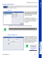
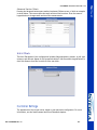
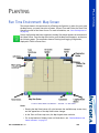
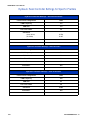
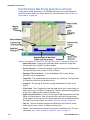
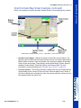
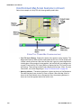
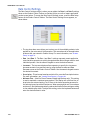
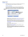
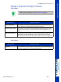
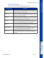
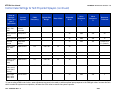
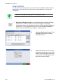
1
INTEGRA User Manual
Firmware Version 1.5
Ag Leader PN 4002086 Rev. C
INTEGRA User Manual
ii
PN:4002086 Rev. C
INTEGRA Firmware Version 1.5
Table of Contents
General Content ................................................................... 1
Introduction and Company Profile ................................................................... 1
What’s New in this Manual? ........................................................................... 6
Conventions Used in this Manual .................................................................... 7
Cautions and Warnings ....................................................................... 7
Cross-References and Web Links ......................................................... 7
Viewing this Manual Online ................................................................. 8
How to Find Information You’re Looking For.......................................... 8
Display Hardware .............................................................................. 9
INTEGRA Installation Instructions ..................................................... 10
Mounting the INTEGRA Display .............................................. 10
INTEGRA Mounting Components ....................................................... 11
INTEGRA Fuse Installation and Replacement...................................... 12
INTEGRA Screen Icon Conventions .................................................... 13
Setup................................................................................ 15
Home Screen Before Configuration................................................................ 15
Setup Screen: Configuration Tab................................................................... 16
Manage Equipment .......................................................................... 17
Setup Buttons............................................................................................. 18
Setup Screen: Product Tab........................................................................... 19
Product Setup.................................................................................. 19
Product Settings.................................................................... 20
Crop Settings ........................................................................ 20
Management Setup ..................................................................................... 21
Grower ............................................................................................ 21
Season ............................................................................................ 21
Field ............................................................................................... 22
Importing and Exporting Field Boundaries................................ 23
Operator .......................................................................................... 24
Console Settings ......................................................................................... 25
General ........................................................................................... 25
Owner ............................................................................................. 26
Features .......................................................................................... 27
Unlocking Features ................................................................ 27
Advanced ........................................................................................ 28
Start Field Operation ................................................................................... 30
Field Finder..................................................................................... 31
Field Operation Options .................................................................... 31
Home Screen After Configuration .................................................................. 32
Configuration Setup Screen .......................................................................... 34
Equipment Configuration Settings...................................................... 34
Implement Switch Settings (for Area Logging) .......................... 34
Equipment Configuration Settings for Rate Control ................... 35
Run Time Environment: Map Screens............................................................ 36
Task Bar Buttons and Status Indicators .............................................. 37
Status Bar Icons .............................................................................. 39
PN: 4002086 Rev. C
iii
INTEGRA User Manual
Map Screen Icons .............................................................................40
Mapping Toolbox Items......................................................................41
Map Legend...........................................................................41
Legend Select ........................................................................41
Legend Settings .....................................................................42
Map Markers Tab....................................................................43
Edit Markers ..........................................................................43
Changing Marker Icons............................................................44
Boundary Tab.........................................................................44
Boundary Settings ..................................................................45
Create Boundary.....................................................................45
Pause Boundary .....................................................................45
Editing Boundaries .................................................................46
Video ...............................................................................................47
Summary Report ..........................................................................................48
Report Details..............................................................................................49
General ............................................................................................49
Configuration....................................................................................50
Report Details - Options ..........................................................51
Auto Generate Report..............................................................51
Copy from Previous Region ......................................................51
Prompt for Report Details ........................................................51
Report Map Appearance ..........................................................51
Smart Reports™ ..........................................................................................52
Create Reports .......................................................................52
Control Channel Report Content ...............................................53
View Reports ....................................................................................54
View Map .........................................................................................54
External Storage Operations ..........................................................................55
Copy Data ........................................................................................55
Upgrade Firmware.............................................................................55
Import Files......................................................................................55
Export Files ......................................................................................56
Manage Files ....................................................................................56
Delete Files............................................................................56
Device Information .......................................................................................57
Devices ............................................................................................57
Display Diagnostics ...........................................................................57
Speed Input Settings.........................................................................58
Calibrate Distance ..................................................................59
Auxiliary Input Settings .....................................................................60
Assign Auxiliary Input Settings.................................................61
Auxiliary Input Assignment: Help .............................................61
Auxiliary Input Settings Diagnostics .........................................62
AutoSwath........................................................................................63
GPS Offsets......................................................................................64
Antenna Offsets......................................................................64
Hitch Tab Settings..................................................................65
Mount Tab Settings (for some Application vehicles) ...................65
Head Tab (for Harvest vehicles) ...............................................65
Swath Section Offsets .......................................................................66
Section Offsets.......................................................................66
Advanced Section Offsets........................................................67
iv
PN:4002086 Rev. C
INTEGRA Firmware Version 1.5
Hitch Offsets......................................................................... 67
Controller Settings............................................................................ 67
GPS.................................................................................. 69
GPS Button ................................................................................................ 69
GPS Setup Screen ....................................................................................... 69
OmniSTAR Settings ..................................................................................... 71
Serial Port Settings...................................................................................... 73
GPS Information ......................................................................................... 75
GPS Information - First Screen .......................................................... 75
GPS Information - Second Screen...................................................... 76
WAAS/OmniStar Information................................................... 76
RTK/NTRIP Information ......................................................... 77
Satellite Plot ......................................................................... 78
GPS Information - NTRIP.................................................................. 79
Guidance .......................................................................... 81
Guidance/Steering Control............................................................................ 81
Lightbar Settings......................................................................................... 82
Guidance Tab on Mapping Toolbox................................................................ 83
New AB Pattern ............................................................................... 86
SmartPath ....................................................................................... 89
Creating a SmartPath Pattern.................................................. 89
Select a Previous SmartPath Pass ........................................... 91
Create AB Line Within a SmartPath Pass ................................. 91
Choose Existing AB Lines Within SmartPath............................. 92
SmartPath Guidance Options .................................................. 92
Save Pattern .................................................................................... 93
Load Pattern.................................................................................... 94
Manage Patterns .............................................................................. 96
Import Pattern....................................................................... 96
Export Pattern ....................................................................... 97
Edit Pattern .......................................................................... 97
Remove Pattern/Remove All Patterns ....................................... 97
Pause ............................................................................................. 98
Reset Pattern................................................................................... 98
Remark A ........................................................................................ 99
Shift ............................................................................................... 99
Nudge............................................................................................. 99
Adaptive Curve............................................................................... 100
About Guidance Patterns ................................................................ 101
A+ Pattern .......................................................................... 101
Pivot .................................................................................. 102
Adaptive Curve .................................................................... 103
Identical Curve .................................................................... 104
Tillage ............................................................................ 105
Run Time Environment: Map Screen ........................................................... 105
About Tillage Configurations....................................................................... 106
Configuration Setup................................................................................... 106
PN: 4002086 Rev. C
v
INTEGRA User Manual
Planting ..........................................................................109
Run Time Environment: Map Screen ............................................................109
Legend Select.................................................................................111
Legend Setup.......................................................................111
About Planting Configurations .....................................................................112
Configuration Setup....................................................................................113
SeedCommand: Machine-Specific Setup ......................................................114
SeedCommand Map Screen Examples...............................................115
Rate Control: Map Screen ...........................................................................117
Rate Control: Product Control Toolbox ..........................................................118
Rate Control Settings ......................................................................119
Loading Prescriptions .................................................................................120
Showing Prescriptions on the Map Screen .........................................121
Row Shutoff...............................................................................................122
Row Shutoff Configuration Setup......................................................122
Row Clutch Setup ...........................................................................124
Row Shutoff Look-Ahead Numbers....................................................125
Checking AutoSwath Performance for Row Shutoff .............................126
If Gaps Appear on the On-Screen Map ..............................................127
Hydraulic Seed Rate Control........................................................................128
Hydraulic Seed Rate Control Configuration ........................................129
Controller Settings for Hydraulic Seed Rate Motor Drives ....................130
Channel Tab settings ............................................................130
Control Valve Settings - PWM ................................................130
Control Valve Settings - Servo ................................................131
Auxiliary Tab settings............................................................131
Hydraulic Seed Controller Settings for Specific Planters .....................132
Hydraulic Seed Meter Calibration Numbers........................................133
Stepper Seed Rate Control ..........................................................................134
Stepper Seed Rate Control Configuration...........................................135
Controller Settings for Stepper Seed Rate Motor Drives .......................136
Channel Tabs .......................................................................136
Auxiliary Tab ........................................................................136
Gear Ratio Calculations for Seed Rate Motors ...............................................137
Determining Drive and Driven Sprockets............................................137
Gear Ratio Drawing - for Multiple Drive Combinations .........................138
Seed Ratio Calculation Example Procedure: Multiple Drives......138
Gear Ratio Drawing - for John Deere ProShaft™ Drives .......................139
Seed Ratio Calculation Example Procedure - for Pro-Shaft™ Drives139
Priming Seed Rate Meters...........................................................................140
Calibrating Seed Rate Meters ......................................................................140
Seed Tube Monitor Module .........................................................................142
Seed Tube Monitor Module Configuration ..........................................142
Seed Monitor Setup ........................................................................143
AutoConfig Procedure ...........................................................144
Seed Tube Sensor Configuration .......................................................145
STMM Split-Row Configurations.............................................145
Seed Monitor Options ......................................................................146
Display Options ....................................................................146
Seed Monitor Options (continued).....................................................147
Table View ...........................................................................147
Seed Monitor Alarms .......................................................................147
KINZE Planter Monitor Module ....................................................................148
vi
PN:4002086 Rev. C
INTEGRA Firmware Version 1.5
KINZE Planter Monitor Module Configuration.................................... 148
KINZE Planter Monitor Setup .......................................................... 150
KINZE Planter Configuration................................................. 150
Planter Configuration Settings............................................... 150
Ground Speed Settings......................................................... 150
Other Sensors...................................................................... 151
EdgeVac ............................................................................. 151
KINZE Sensor Configuration ................................................. 151
Muxbus Sensor Detection (for KINZE Planter Monitor) ............ 152
Sensor Information (for KINZE Planter Monitor)...................... 154
KINZE Seed Monitor Alarms ................................................. 155
KINZE Magnetic Coil Speed Sensor Calibration ...................... 156
KINZE EdgeVac Calibration .................................................. 157
KINZE Planter Monitor Options........................................................ 158
Display Options ................................................................... 158
Table View .......................................................................... 158
KINZE Display Items on Equipment Tab........................................... 159
Troubleshooting ........................................................................................ 160
Fixing Overplanting and Underplanting in AutoSwath......................... 160
Hydraulic Seed Control: Zero Flow Offset Variation ............................ 161
Stepper Seed Control Meter Alarms.................................................. 163
Alarms on KINZE Planter Monitor .................................................... 164
Application...................................................................... 167
Run Time Environment: Map Screen ........................................................... 167
Legend Select................................................................................ 168
About Application Configurations ..................................................... 168
Configuration Setup........................................................................ 169
Add Products ................................................................................. 170
Add Product Mix ............................................................................ 170
Tank Mix Setup ................................................................... 170
Dry Fertilizer Blend Setup .................................................... 171
DirectCommand: Machine-Specific Setup .................................................... 172
DirectCommand Map Screen Examples........................................................ 173
Rate Control: Product Control Toolbox ......................................................... 177
Rate Control Settings...................................................................... 178
Rate Control: Container Level .......................................................... 179
Tank Fill ............................................................................. 179
Tank Empty ........................................................................ 179
Tank Partial Fill................................................................... 179
Adjust Container Amount...................................................... 179
Tank Alarms........................................................................ 180
Loading Prescriptions ................................................................................ 181
Showing Prescriptions on the Map Screen ........................................ 182
Shape File Conversion................................................................................ 183
Liquid Application Control.......................................................................... 187
Liquid Application Control Configuration .......................................... 187
Liquid Application Controller Settings .............................................. 190
Control Valve Settings - PWM................................................ 191
Control Valve Settings - Servo, Calibrated Reflow and Ramsey Valve192
Configuration Settings for Liquid Application Controllers.................... 193
PN: 4002086 Rev. C
vii
INTEGRA User Manual
Calibrate Pressure ................................................................193
Fence Row Nozzle Indicators............................................................194
Liquid Application Diagnostics .........................................................195
Direct Injection ..........................................................................................196
Direct Injection Configuration Setup .................................................196
Direct Injection Configuration Setup (continued) ................................197
Direct Injection Configuration Setup (continued) ................................198
Controller Settings for Direct Injection ..............................................199
Rate Response Warning ........................................................199
Flow Monitor Warning ...........................................................199
Calibrating an Injection Pump ..........................................................200
Priming an Injection Pump ..............................................................202
Injection Diagnostics .......................................................................203
NORAC UC5 ..............................................................................................204
NORAC UC5 Setup .........................................................................204
Automatic Setup ..................................................................205
Retune ................................................................................205
Minimum Height Settings......................................................206
NORAC UC5 Run Time Operations....................................................207
Engage Button .....................................................................207
Boom Height Control Options Button ......................................207
Boom Height Control Options Screen......................................208
Boom Height Diagnostics .................................................................208
OptRx Crop Sensor Module..........................................................................209
About OptRx...................................................................................209
Remote Sensing Explained ....................................................209
How the Active Light Sensor Works ........................................209
OptRx Sensor Cable Installation .......................................................210
OptRx Installation Checklist ..................................................210
OptRx Crop Sensor Configuration......................................................211
Create an OptRx V.I. Reference Value ...............................................213
V.I. Reference Value Creation Checklist ..................................213
Scan a Reference Strip .........................................................213
OptRx Crop Sensor Settings .............................................................216
Crop Sensor Setup ..........................................................................217
Sensor Setup .......................................................................218
Spinner Spreader Granular Control...............................................................219
Spinner Spreader Control Configuration.............................................219
Spreader Control Settings ................................................................221
Spreader Control: PWM Control Valve .....................................221
Spreader Control: Servo Control Valve .....................................222
Spreader Control: Spinner Tab ...............................................223
Spinner Spreader Run Time Operations.............................................224
Spreader Control Screen........................................................224
Fan Frame & Feed Gate Actuator Settings...............................225
Spreader Control: Routine Operations .....................................225
Spreader Control: Chain Oiler ................................................225
Spreader Control: Static Calibration........................................226
Spreader Control: In-Field Calibration.....................................227
Strip Till....................................................................................................228
Strip Till Configuration ....................................................................228
Strip Till Control Settings.................................................................230
Spreader Control: PWM Control Valve .....................................230
viii
PN:4002086 Rev. C
INTEGRA Firmware Version 1.5
Spreader Control: Servo Control Valve .................................... 231
Spreader Control: Auxiliary Tab ............................................. 232
Strip Till Run Time Operations ........................................................ 233
Strip Till Control Screen ....................................................... 233
Static CFR Calibration Procedure .......................................... 234
In-Field Calibration Procedure (Strip Till) ............................... 235
Troubleshooting ........................................................................................ 236
Troubleshooting DirectCommand Liquid Applications......................... 236
Troubleshooting Direct Injection Configurations................................. 239
Direct Injection: Pump Doesn’t Run ...................................... 239
Direct Injection: Pump Runs Full Speed ................................ 240
Direct Injection: Application Error ......................................... 241
Direct Injection: Discharge Flow Sensor Error ......................... 242
Direct Injection: Inlet Restriction .......................................... 243
Troubleshooting OptRx Error Messages ............................................. 244
Troubleshooting DirectCommand Granular Applications ..................... 245
Troubleshooting Serial Control Applications (Liquid and Granular) ...... 246
Troubleshooting Serial Control Applications (Liquid Only)................... 246
Troubleshooting Serial Control Applications (Granular Only) ............... 246
Miscellaneous ........................................................................................... 247
Glossary of Application Settings....................................................... 247
Configuration Settings.......................................................... 247
Speed Input Settings ........................................................... 247
Automatic Swath Control Settings ......................................... 248
Auxiliary Input Settings ........................................................ 248
Controller Settings ............................................................... 249
Controller Settings: Direct Injection Pump Calibration ............. 250
Field Notes ......................................................................... 251
Run Screen ......................................................................... 251
Glossary of OptRx Terminology ........................................................ 252
Fertilizer Default Product Settings ................................................... 253
John Deere Specific Instructions...................................................... 254
Control Valve Settings..................................................................... 255
Liquid Product Control Valve Configuration Options................. 255
Servo Control Valve Settings (By Manufacturer) ................................. 256
Control Valve Settings for Self-Propelled Sprayers ............................. 257
Liquid Servo Settings Description .................................................... 262
Liquid PWM Control Valve Settings Description ................................. 263
Spinner Spreader Servo Settings Description .................................... 264
Spinner Spreader PWM Control Valve Settings Description ................. 265
Spinner Speed PWM Valve Settings Description ................................ 266
Dickey-John NH3 Conversions ......................................................... 267
Conversion Formulas ............................................................ 267
Harvest ........................................................................... 269
Run Time Environment: Map Screen ........................................................... 269
Harvest Status Items ...................................................................... 270
Harvest Diagnostic Button on Map Screen ........................................ 271
Legend Select................................................................................ 271
Map Screen: Flow Delay.................................................................. 272
Region Selection: Options Screen .................................................... 272
PN: 4002086 Rev. C
ix
INTEGRA User Manual
Tracking Varieties and Changing Regions...........................................273
Variety Tracking menu and Automatic Variety Tracking.............274
Automatic Variety Tracking ....................................................274
Automatic Region Changing...................................................274
In-Field Messages.................................................................275
Importing Variety Maps....................................................................276
Importing Variety Map Procedure ...........................................276
Error Messages at Variety Map Import.....................................277
AutoSwath Sensitivity Settings .........................................................278
About Harvest Configurations ......................................................................279
Pre-Harvest Checklist .................................................................................280
INTEGRA Display Preparation ..........................................................280
Vehicle Inspection...........................................................................280
Calibration Sequence ......................................................................280
Configuration Setup Settings .......................................................................281
Header Settings ..............................................................................283
Calibrate Header Sensor........................................................283
Header Offset.......................................................................284
Vibration Calibration........................................................................285
Temperature Calibration ..................................................................287
Moisture Calibration ........................................................................288
Grain Weight Calibration ..................................................................289
Grain Weight Calibration (continued).................................................290
Grain Weight Calibration (continued).................................................291
Adding a New Calibration.................................................................292
Area Calibration ..............................................................................294
Grain Harvest Diagnostics ...........................................................................295
Harvest Diagnostic Notes .................................................................295
Appendix.........................................................................297
System Diagrams Reference ........................................................................297
INTEGRA File Formats................................................................................298
Module LED Diagnostic States.....................................................................299
Company Warranty Statement......................................................................300
x
PN:4002086 Rev. C
Introduction and Company Profile
ABOUT US
Welcome to the Ag Leader Technology family. Ag Leader Technology, Inc. is the global
leader in yield monitor and precision farming systems and is committed to meeting the
present and future needs of the agriculture industry by providing high quality products
and first class customer support.
INNOVATION
Ag Leader Technology manufactures and sells products which support a wide array of
precision farming practices. These include grain yield monitoring, application rate control
and monitoring, variable rate fertilizer application, site-verification, GPS guidance and
interface to Autosteer technologies.
COMPATIBILITY
Ag Leader Technology offers compatibility and supports integration of many different
types and brands of equipment used for precision farming. The latest equipment available
is supported as well as older series of combines, planters, sprayers, tillage equipment,
etc.
QUALITY AND SUPPORT
Ag Leader Technology and continues to provide the best customer support in the industry.
Precision farming doesn't come without questions. Ag Leader is committed to providing
the most responsive, knowledgeable and friendly technical support available. Our
technical support team is available seven-days-a-week during peak seasons to answer
your questions on the operation of Ag Leader products.
WE WANT TO HEAR FROM YOU!
Feel free to call and discuss:
• Operational questions about the INTEGRA™ system
• Features you would like to see implemented to improve the system or features you
would like to see added to the system to increase functionality
INTEGRA SYSTEM
The Ag Leader INTEGRA display is the full-featured, year-round hub of any precision
farming operation. A large, full-color 12.1” HD touchscreen display is easy to read and
offers powerful, year-round precision farming tools. Built-in manual guidance, full-screen
mapping, planter and application control, yield monitoring, real-time data logging and
automated steering make up the core functionality of the INTEGRA display.
PN: 4002086 Rev. C
1
GENERAL CONTENT
GENERAL CONTENT
INTEGRA User Manual
SERVICE
There are no user-serviceable parts inside the INTEGRA display. Contact Ag Leader
Technical Support for a Return Material Authorization (RMA).
ph: (515) 232-5363
fax: (515) 232-3595
e-mail: [email protected]
CAUTION: This display has an internal lithium coin cell battery that is good for the life
of the product and does not need to be replaced. There is a risk of explosion if the
battery is replaced by an incorrect type. Dispose of used batteries according to the
battery manufacturer’s instructions.
SYSTEM USES
• Manual Guidance
• ParaDyme™ automated
steering
• Granular and liquid fertilizer
application
• Liquid spray system control
• Video Camera Inputs
• NH3 application control
• Mapping tillage operations
• NORAC UC5™ Boom Height
Control
• Mapping and logging product
application
• Mapping of all field
boundaries, sub-boundaries,
waterways and terraces
• Grain yield monitoring
• Variety logging
• Application control of multiple
bin spinner spreaders
• Chemical Injection
• Row Shutoff module
• Hydraulic Seed Rate Control
module
• Stepper Seed Control module
Note: For a complete description of all supported file format types and their
uses, see “INTEGRA File Formats” on page 298.
2
PN:4002086Rev.C
SYSTEM FEATURES
• 12.1” touch screen
• Perspective 3D View Map
• Sunlight-readable screen with
High-Definition, 1024 X 768
resolution, 16-bit color.
• Report preview
• Sunlight-readable screen
• 4 GB internal memory
• Rugged sealed enclosure
• Compatible with most NMEA
GPS receivers
• DirectCommand and
SeedCommand product
control using industrystandard CAN-bus interface
• Adjustable volume control
• Automatic field selection
• Automated module firmware
upgrade
• Advanced GPS Diagnostics
• USB media slot
• 28-pin plug compatible with
InSight and EDGE displays.
• 28-pin auxiliary connection
• Support for as many as four
video cameras
• Light sensitivity sensor
• Dual stereo speakers
• RAM mount
USB FLASH DRIVE
INTEGRA kits include a USB Flash Drive which you can use to save and transfer your data in
and out of the display.
COLOR TOUCH SCREEN
The INTEGRA display features a 12.1-inch color touch screen display. The touch screen allows
easy and intuitive navigation through the screens on the display without the need for any
external keypad or mouse devices. Here are a few key things to remember if you are new to
using a touch screen device:
• Do not use any sharp objects for running the touch screen device, this could result in
damage to the display. Using the tip of a finger is the recommended method of
operating the INTEGRA display touch screen.
• Do not use any harsh chemicals to clean the touch screen. Using a damp soft cloth or
an anti-static wipe made specifically for cleaning computer displays is the correct way
to clean the screen and the INTEGRA enclosure.
• The touch screen requires only a gentle touch of about half-second in duration to
operate correctly. A common mistake new users make is to try to navigate too quickly
through the system using firm taps instead of gentle presses on the display screen.
PN: 4002086 Rev. C
3
GENERAL CONTENT
INTEGRA Firmware Version 1.5
INTEGRA User Manual
CAN-BUS TECHNOLOGY
The INTEGRA system uses Controller Area Network (CAN) technology. CAN systems are
comprised of individual modules, each with their own high speed processor, connected
through a high-speed communications cable. CAN has many benefits, including greater
ability to configure and expand the system, compatibility, simpler installations with less
wiring, and increased system dependability.
TECHNICAL SPECIFICATIONS
Do not exceed the specifications below:
Storage Temperature: -20°C to +80°C.
Operating Temperature: -10°C to +70°C
Operating Input Voltage: 9 –16 V DC
Max Current Rating: 2.5 amp.
CAUTION: Exceeding these specifications may result in degraded operation and/or
damage to the display.
4
PN:4002086Rev.C
SYSTEM AND UPGRADES
Ag Leader Technology will periodically provide operating program updates that will improve
the performance of your INTEGRA System. Required software updates will be available free
of charge for download from www.agleader.com. On occasion, major releases will be made
available that have significant product feature additions or enhancements. These optional
software updates may have an additional fee associated with them.
AUTOMATED MODULE FIRMWARE UPGRADE
In the INTEGRA display, all display and module firmware upgrades are packaged in a single
.fw2 file. The module firmware files are stored internally in the display. A warning alerts you
when a module upgrade is required. You can upgrade all files in a single batch by using an
upgrade screen. For more information, see “Advanced” on page 28.
PRODUCT REGISTRATION
When registering your Ag Leader Technology products by one of the following methods, you
can elect to receive notice of any new product updates or features.
Register by mail: Ag Leader Technology
2202 South Riverside Dr.
Ames, IA 50010
Register by Fax: 515-232-3595
Register at the Ag Leader Web site at http://www.agleader.com
PN: 4002086 Rev. C
5
GENERAL CONTENT
INTEGRA Firmware Version 1.5
INTEGRA User Manual
What’s New in this Manual?
This INTEGRA User Manual supersedes the Version 1.2 edition of the INTEGRA User Manual,
which was published in April 2010. As such, it has added information, including firmware
upgrades that have been made in INTEGRA Firmware 1.5. You can quickly view some of
these updates to this manual on the following pages.
SETUP
• Merged Grower, Farm and Field Selection screens in the Field Operation Wizard.
For more information, see “Start Field Operation” on page 30.
• Added Assign function to Auxiliary Input Settings feature. For more information,
see “Auxiliary Input Settings” on page 60 and also “Assign Auxiliary Input Settings”
on page 61.
GUIDANCE
• Added the SmartPath™ feature, which gives guidance from any previously-driven
pass. For more information, see new settings at “Guidance Tab on Mapping Toolbox”
on page 83 to page 85. See also “SmartPath” on page 89, “Creating a SmartPath
Pattern” on page 89, “Select a Previous SmartPath Pass” on page 91, “Create AB Line
Within a SmartPath Pass” on page 91, “Choose Existing AB Lines Within SmartPath”
on page 92 and “SmartPath Guidance Options” on page 92.
SEEDCOMMAND (SHOWN
IN
PLANTING SECTION)
• The feature previously known as Clutch Control has been renamed Row Shutoff.
Other than the terminology change, no functionality of this feature has changed
for this firmware revision. For more information, see “Row Shutoff” on page 122.
Also see new appearance of Row Shutoff screen at “Row Clutch Setup” on page 124.
DIRECTCOMMAND™ (SHOWN
IN
APPLICATION
SECTION)
• Added information on Liquid Application Diagnostics. For more information, see
“Liquid Application Diagnostics” on page 195.
• Added Ramsey Valve to liquid product control valve configuration options. For
more information, see “Liquid Product Control Valve Configuration Options” on
page 255 and also “Control Valve Settings - Servo, Calibrated Reflow and Ramsey
Valve” on page 192.
HARVEST
• New in INTEGRA 1.5, you can import variety maps from Ag Leader SMS™ software.
For more information, see “Importing Variety Maps” on page 276, “Importing Variety
Map Procedure” on page 276 and “Error Messages at Variety Map Import” on
page 277. See updated Options screen with Variety Map Import button at “Region
Selection: Options Screen” on page 272. Also see .ref file description at “INTEGRA
File Formats” on page 298.
6
PN:4002086Rev.C
Conventions Used in this Manual
Cautions and Warnings
The user manual uses the following text formatting schemes to call attention to information
related to simplifying system operation and proper operating practices to prevent accidental
data loss. If in doubt about the results of performing an action or deleting an item from the
system, back up all system files to the USB external drive prior to proceeding with the action.
Icon
Description
Provides informative tips to assist with system setup, calibration, and
operation.
Indicates specific settings, calibrations, and procedures that must be
followed for proper system performance and operation.
Indicates specific instructions to avoid accidental loss of data and system
configurations settings.
Cross-References and Web Links
Throughout this manual, numerous cross-references are provided to other pages or sections.
These cross-references are always shown in blue, italic text; and list the title and page
number as in the following example: To find the information you’re looking for, see “How to
Find Information You’re Looking For” on page 8. If you are viewing this manual in a .PDF
format, you can click on this blue text and go directly to the link.
Links to web sites are shown in blue, italicized, and underlined text, as in the following
example: To see the Ag Leader Technology Web site, go to this Web link: www.agleader.com.
PN: 4002086 Rev. C
7
GENERAL CONTENT
INTEGRA Firmware Version 1.5
INTEGRA User Manual
Viewing this Manual Online
This user manual can be viewed online at Ag Leader’s Web site. To view an online version,
go to the Ag Leader Web site and click the Customer Support link. You will see a page
titled “Product Manuals.”
To view and/or print the INTEGRA User Manual online, you will need the Adobe Acrobat
or Adobe Reader .pdf file format. The Adobe Reader software comes pre-installed on
most personal computers. If Adobe Reader is not installed on your computer the program
is available for download at no charge. A link to the Adobe download site is located at
the Ag Leader Web site.
How to Find Information You’re Looking For
What do you do if you cannot find the information that you’re looking for? There are three
different ways at your disposal to find specific information quickly. These steps can
include:
1 Look up the information in the Table of Contents.
2 Look up the information in the section indexes that are located at the end of
each manual section (Planting, Tillage, Application, and Harvest).
3 Use the Adobe Reader’s search function. While viewing this manual online in
PDF format, press the CTRL+F buttons on your keyboard. A search menu should
appear, and from here, you may enter in a search term.
8
PN:4002086Rev.C
Display Hardware
Number
Description
1 USB media
slot
Used for data transfer in and out of the display.
2 Dual stereo
speakers
The built-in stereo speakers are used for audible warnings. The speakers’ volume
can be adjusted through the console setup routine.
3 RAM mount
For more information, see “INTEGRA Mounting Components” on page 11
4 VGA video
output
Can be used to connect to a video projector for demonstration purposes.
5 28-pin
auxiliary
connection
Used for camera input.
6 28-pin plug
The 28-Pin round connector contains CAN, RS-232 serial, and system power and
ground connections. It is compatible with the InSight and EDGE displays, and
includes an Ethernet connection for ParaDyme automated steering.
7 Power/Reset
switch
The Power/Reset switch is used for turning the INTEGRA display on and off in
installations where the system is connected to a continuous power supply. If the
INTEGRA display ever stops responding, the manual power switch may be held in
for five seconds to restart the system. Only do this as a last resort, data loss could
occur during times of improper shutdown.
8 Light
sensitivity
sensor
Used to automatically dim the display during nighttime or low-light situations.
9 Power light
The power light displays one of three states: When it is green the display is on;
when it pulses amber the display is in Standby Mode, and when it is solid amber
the display is running on battery power.
PN: 4002086 Rev. C
9
GENERAL CONTENT
INTEGRA Firmware Version 1.5
INTEGRA User Manual
INTEGRA Installation Instructions
All machine installation and mounting kits are shipped with instructions specific to that
kit. Instructions include special details relating to mounting, wiring and display
configuration.
Mounting the INTEGRA Display
Mount the display to a secure support inside the vehicle cab. The following must be
considered when choosing a mounting location:
• The display must be readily accessible to the machine operator.
• The display must not obstruct the machine operator's normal driving view.
• The display must not interfere with or limit access to any of the existing machine
controls.
• The INTEGRA CAN system cabling be routed and secured without interfering with
existing machine controls.
WARNING: If drilling holes is required during the mounting process, care must be taken
to insure that damage is not done to existing vehicle wiring, mechanical, or cab
structure. Refer to vehicle manufacturer documentation for specific details on your
equipment. Follow all OEM instructions, cautions, and warnings when working around
equipment.
10
PN:4002086Rev.C
INTEGRA Mounting Components
Callout
Number
Description and Part Number
1
RAM Base, PN 4000280
2
RAM Arm - 5”, PN 4000279
3
2”X6” Base, PN 400187
PN: 4002086 Rev. C
11
GENERAL CONTENT
INTEGRA Firmware Version 1.5
INTEGRA User Manual
INTEGRA Fuse Installation and Replacement
CAUTION: The fuse is to be placed in the fuseholder in-line with the battery power
cable and used with display only.
12
PN:4002086Rev.C
INTEGRA Screen Icon Conventions
The following control buttons are made available for entering names and calibration values
into the INTEGRA system.
Function Button
Data Entry Screen
An on-screen Keyboard is made available when
appropriate for use during all setup processes.
Press the keyboard button to access the on-screen
text entry screen shown at the right.
An on-screen Numeric Keypad is made available
for changing configuration settings and calibration
numbers. Press the keypad button to access the
on-screen numeric entry screen shown at the
right.
PN: 4002086 Rev. C
13
GENERAL CONTENT
INTEGRA Firmware Version 1.5
INTEGRA User Manual
14
PN:4002086Rev.C
SETUP
SETUP
Home Screen Before Configuration
Prior to setup, most of the functionality of the INTEGRA system is not available until the
basic setup process is completed, and the Home screen will look like the picture below.
The Run Time Environment is not accessible, because the Map button does not appear on
the task bar at bottom. Specific functions available at the Home screen are described in
the table below. Items in the Status Bar at top and Task Bar at bottom are described at
“Task Bar Buttons and Status Indicators” on page 37 and “Status Bar Icons” on page 39.
You must complete these initial
configuration steps for the Run Time
Environment to be active:
1 Grower, Farm, and Field
management. For more information,
See “Management Setup” on page 21.
2 Equipment Operating Configuration.
You can access Configuration Setup by
pressing the Setup (wrench) button at
the upper right-hand portion of the
Home Screen. For more information,
see “Setup Screen: Configuration Tab” on
page 16.
3 Product setup. For more information,
see “Setup Screen: Product Tab” on
page 19, as well as the additional
configuration information described in
each Operations chapter.
4 Start Field Operation. For more
information, “Start Field Operation” on
page 30.
PN: 4002086 Rev.C
15
INTEGRA User Manual
Setup Screen: Configuration Tab
The Setup screens are comprised of two tabs: the Configuration Tab, and the Product Tab.
The Configuration Tab buttons are explained below; the Product Tab is described at
“Setup Screen: Product Tab” on page 19. The Setup buttons are described below and on
the following page.
The Setup screen’s Configuration Tab is where you can create new configurations, view
configuration information, as well as view and change configuration settings. Begin by
going to the Home Screen, and pressing the Setup (wrench) button. The Configuration
Setup Screen appears, as shown below.
.
Button
Description
In the upper left-hand corner of the screen is the Operating Configuration drop-down
menu. Use this to select the type of operating configuration you wish to view - Tillage,
Planting, Application or Harvest.
Press the Add (plus sign) button to add an Operating Configuration. At the following
screen, choose an operating configuration type, such as Tillage, Planting, Application,
etc.) From here, an on-screen wizard continues you through each step of the
configuration process.
• When finished, the new configuration appears in the list below the Operating
Configuration drop-down menu.
• When you highlight the configuration, the Name of that configuration and the
Equipment within it appear on the Setup Tree, located to the right of the Add
button.
• Information regarding configurations for specific field operations can be viewed in
each Operations chapter.
Press the Edit (keyboard) button to edit the Configuration Name.
Press the Setup (wrench) button to adjust Configuration Settings and other settings. For
more information, see “Configuration Setup Screen” on page 34.
16
PN:4002086 Rev. C
Configuration Setup Screen (continued)
Button
Description
Press the Delete (minus sign) button to delete an Operating Configuration.
Caution: When you delete a configuration all data logged with that configuration
will also be deleted! However, all log files will remain in memory until exported to the
USB drive.
Press the Manage Equipment button to add, edit, or delete information for information
regarding a particular vehicle, implement or controller; or to adjust Implement offsets.
For more information, see “Manage Equipment” on page 17.
Manage Equipment
By pressing the Manage Equipment button, found at the top right-hand side of the Setup
screen’s Configuration Tab, you can either:
• Use the drop-down menu to edit settings for an existing Vehicle, Implement or
Controller that you created with the Configuration Wizard in the Operating
Configuration.
• Create a new Vehicle, Implement and Controller.
PN: 4002086 Rev. C
17
SETUP
INTEGRA Firmware Version 1.5
INTEGRA User Manual
Setup Buttons
The Setup buttons, shown at the bottom of the Setup screens, are where you can toggle
between screens that adjust settings for Configuration, Management, GPS and display
Console.
Button
Description
The Configuration button is where you adjust the configuration settings
particular to your vehicle and equipment; as well as enter and edit product
information. For more information, see “Manage Equipment” on page 17,
“Setup Screen: Product Tab” on page 19, as well as “Configuration Setup
Screen” on page 34.
The Management button is where you can access and edit Grower, Farm, Field
and Operator information. For more information, see “Management Setup” on
page 21.
The GPS button is where you can adjust Guidance settings, GPS settings, and
lightbar settings (if applicable). For more information, see “GPS” on page 69
and also “Guidance” on page 81.
The Console button is where you can adjust settings for Time and Date,
brightness and volume settings, operating units, language; enable video; view
features; and also create and restore backups. For more information, see
“Console Settings” on page 25.
18
PN:4002086 Rev. C
Setup Screen: Product Tab
Product Setup
The Setup Product Tab is where you can perform the following tasks:
• Add or import Planting products.
• Add or import Application products.
• Add Application Product mixes (such as a tank mix, or a dry blend of multiple
products).
• Add or import Harvest products.
Button
Description
Press the Add (plus sign) button to add or import a Product. At the following screen,
choose a Product Option: Add Product, Import Product, or Add Product Mix (if in
Application). From here, an on-screen wizard continues you through each step of the
configuration process.
• When finished, the new product appears in the list below the Operating
Configuration drop-down menu.
• When you highlight the configuration, the product information appears to the right
of the Add button.
• Specific planting and application product information can be viewed in those
respective chapters.
Press the Edit (keyboard) button to edit the Product Name.
Press the Delete (minus sign) button to delete a product.
Caution: When you delete a product all regions using that product will also be
deleted!
Crop Settings
For more information, see “Crop Settings” on page 20.
Edit Info
The Edit Info button opens the Product Settings screen, where you can where you can
edit product information for an existing product in the Product List. For more
information, see “Product Settings” on page 20.
Yield and Moisture
Operators using a Harvest operation can use the drop-down menu underneath Legend
Settings to edit legend settings for Yield and Moisture.
Edit Legend
Pressing the Edit Legend button summons the Legend Settings screen, where you can
change Rate Legend settings. For more information, see “Legend Settings” on page 42.
PN: 4002086 Rev. C
19
SETUP
INTEGRA Firmware Version 1.5
INTEGRA User Manual
Setup Screen: Product Tab (continued)
Product Settings
The Product Settings screen is where you can edit product information for an existing
product in the Product List. To go to the Product Settings screen, first go to the Setup
screen’s Product Tab. Press the Edit Info button, and the Product Settings screen appears,
as shown below. At the Product Settings screen, you can enter information regarding the
following items:
• Manufacturer - Enter the Manufacturer and
Common Name, if desired.
• EPA Number - Enter the EPA Registration
Number which is listed on the product’s
container label.
• Restricted Use Pesticide - If the product is a
Restricted Use Pesticide, press the check box.
This information will also be included for your
records.
Crop Settings
The Crop Settings screen is where you can edit product information for an existing
Harvest product in the Product List. To go to the Crop Settings screen, first go to the Setup
Screen’s Product Tab. Underneath the Crop Settings box, press the Edit button, and the
Crop Settings screen appears, as shown below. At the Crop Settings screen, you can enter
information regarding the following items:
• Dry % - The percentage of grain moisture used
to calculate Dry Bushels.
• Weight to Volume - The Weight to Volume
conversion number used to calculate bushels.
• Expand bushels for all grains below dry % If the moisture of the harvested crop is below
the dry percentage, the INTEGRA system
increases weight to show the weight which
would be shown if the crop equalled or
exceeded the dry percentage.
20
PN:4002086 Rev. C
Management Setup
The Management tabs, which are accessible from the Management button on the Setup
screen, include Grower, Season, Field, and Operator.
Grower
The Grower is a global setting that refers to the business or person that the system is in
operation for. Contact information can also be entered for each Grower. The Grower
information will be passed into mapping software for automatic Grower setup within desktop
software.
• Press the Add (plus sign) button to add a Grower.
• Press the Delete (minus sign) button to delete a Grower.
• You may edit an existing name of a Grower by highlighting that name and pressing the
on-screen keyboard button.
• Press the Edit button to enter information for the Grower’s Name, Business Phone,
Address, Applicator License, Home Phone, Mobile Phone, and Email information.
Note: Personal Information entered at this screen can be added or edited at any
time.
Season
A season is defined as the calendar year that the crop will be harvested. Creating a season
and setting it to active is required prior to the system logging any data.
The seasons are displayed in lists, with the
Active season displayed in bold face type.
All new data is logged to the active season;
therefore a season must be set as Active
before you can log any new data to it.
•Press the Add (plus sign) button to add a
Season.
•Press the Delete (minus sign) button to
delete a Season.
•You may edit an existing name of a Season
by highlighting that name and pressing the
on-screen keyboard button.
• Press the Set Active button to set the season selected in the Summary list box to the
active season.
• Press the Season Reminder button to set the date that the system will prompt the user
to create a new season.
PN: 4002086 Rev. C
21
SETUP
INTEGRA Firmware Version 1.5
INTEGRA User Manual
Field
In the display, farms are subdivided into fields. You can associate Field names with a
particular Grower. If the display will be used for multiple Growers, enter each Grower
business name and associate the field names with the correct grower when the fields are
set up within the system.
In the Field Tab, select a Grower
underneath the drop-down menu at the
top. Each farm of that particular
grower is shown in a list, with the fields
within that farm as subcomponents
within that list.
•Press the Add (plus sign) button to add
a Field.
•Press the Delete (minus sign) button to
delete a Field.
•You may edit an existing name of a
Field by highlighting that name and
pressing the on-screen keyboard
button.
• You may edit the Farm Name and Field Name information by highlighting that name
and pressing the setup (wrench) tool. The Field Information screen appears, as
shown below.
The Field Information screen opens,
showing the name of that field in the
Title Bar. Field Name information that
can be added or edited with the onscreen keyboard buttons include Farm,
County, Township, Range, Section
Number, Area, FSA Number, FSA Area
and Legal Description.
Notes:
•Area is shown in the total acres
(hectares) of the field.
•FSA Number refers to the U.S. Farm
Service Agency’s four-digit number
assigned to every field. FSA Area
refers to tillable acres as established
by the FSA.
• If you wish to center the map on the current GPS position, press the Clear Bounds
button.
Note: The Clear Bounds feature is particularly useful if you have flyer points
or have logged a point outside the mappable range of your current location.
22
PN:4002086 Rev. C
Importing and Exporting Field Boundaries
Boundaries can be created with the INTEGRA display or imported from desktop GIS
software. Any boundary files present in the INTEGRA display can also be exported for
use in desktop mapping software.
Note: For more information on creating boundaries, see “Create Boundary” on
page 45.
To import a boundary from the USB drive, first go to the Setup Field Tab, highlight the
correct field in the Farm/Field list and press the USB Import button.
The File Selection screen appears, as shown below. Highlight the desired file to import.
Press the green check mark button to
complete the import process.
If you would like to export a boundary to the USB drive, highlight the correct field in the
Farm/Field list. Then press the USB Export button. At the File Selection Screen, highlight the
desired field to export. A screen will appear telling you that the boundary was exported
successfully. Press the green check mark button to return to the field setup screen.
PN: 4002086 Rev. C
23
SETUP
INTEGRA Firmware Version 1.5
INTEGRA User Manual
Operator
A machine operator can be added at the Operator Tab.
• Press the Add (plus sign) button to add an Operator.
• Press the Delete (minus sign) button to delete an Operator.
• You may edit Operator information by highlighting that name and pressing the
setup (wrench) tool. At the Personal Information screen, you can use the on-screen
keyboard buttons to add or edit information for that Operator, including Name,
Business Phone, Fax, Address, Applicator License, Home Phone, Mobile Phone,
and Email.
24
PN:4002086 Rev. C
Console Settings
To view the Console Screen, press the Console setup button at the bottom of the setup
screens. The Console screen consists of three tabs: General, Features and Advanced.
• The General Tab includes settings related to Time, Date, display console screen
settings, operating units, video and display owner information. For more information,
see below.
• The Features Tab lists unlocks for a particular console. For more information, see
“Features” on page 27.
• The Advanced Tab includes information related to log files and system backups. For
more information, see “Advanced” on page 28.
General
The Setup General Tab is shown below. It consists of the following items:
• Time and Date settings. To change these, press on this button and use the up and
down arrow keys to adjust the hours, minutes, A.M./P.M. settings, month, date and
year. To make these changes effective, press the checkmark/ Shutdown button.
Note: The INTEGRA display will then shut down immediately. If you do not want
to shut the monitor down, press the Close (Red X) button; however the
time/date changes will not be accepted until the display is shut down and
restarted.
• Brightness and volume percentages. To change these, press the Brightness/Volume
button and use the up and down arrow buttons to change the percentage of the Display
Brightness and Speaker Volume.
Note: Pressing the Automatic box will display the Display Brightness - Trim
setting, which makes adjustments to the INTEGRA’s brightness according to the
available or ambient light.
PN: 4002086 Rev. C
25
SETUP
INTEGRA Firmware Version 1.5
INTEGRA User Manual
Console General Tab (continued)
• Calibrate Touchscreen. Press this to launch the Touch Screen Calibration wizard.
Calibrate the touch screen by following the on-screen instructions.
CAUTION: Do not use any sharp objects to operate the touch screen or the display may
be damaged.
• Time Zone. Use the drop-down menu to select your time zone.
• Language/Country Selection. Use the drop-down menu to select the language.
• Operating Units. Select either Imperial or Metric.
• Enable Video. Enables input from up to four video cameras.
Owner
This tab contains functionality for setting up a Display Owner and making any needed
edits to the owner personal information. The Display Owner information is used in the
product application report feature of application rate control. An image for the Display
Owner can be imported for inclusion on product application reports.
• Name, Address, Phone. Displayed on Owner Tab.
• Select Owner. Press to display a list of all farm and business contacts set up in the
system. The on-screen dialog that is displayed will give option to select an existing
person/business or create a new one to be used as the Display Owner.
• Edit Info. Press to edit or add the personal information for the Display Owner.
• Import Image. Press to import the image file that is displayed with the Display
Owner information on any application reports that are created. The system
currently supports .bmp and .png file formats. Size is limited to a maximum of 200
pixels wide x 100 pixels tall.
• Clear Image. Press to delete the Business Owner image.
26
PN:4002086 Rev. C
Features
Unlocking Features
The Setup Features Tab is where you can enter unlock codes. Unlock codes are unique to the
serial number of each INTEGRA display and the feature registration number. You must supply
these numbers to your Ag Leader dealer when purchasing any unlock codes. Use the on-screen
keyboard button to enter the unlock code and press the green check mark button to enable
the feature.
Note: Once a feature is unlocked, that feature remains with that display and
cannot be transferred to another.
PN: 4002086 Rev. C
27
SETUP
INTEGRA Firmware Version 1.5
INTEGRA User Manual
Advanced
The Advanced Tab allows you to specify settings for copying log files; specify Key Switch
Standby settings; view and manually upgrade module firmware; and create and restore
backup files.
CAUTION: The Export Diagnostic Files, Advanced Parameters, Copy Debug Files,
Clear Debug Files and Service Mode functionality on the Advanced Tab is reserved for
use by Ag Leader Engineering. DO NOT change any of these settings without specific
instruction from Ag Leader Technology.
• Key Switch Standby. This setting allows the INTEGRA display to remain powered
up after the vehicle power has been shut down. Instead, the display will switch into
a standby mode and the screen will go dark and appear to be shut off; however the
power light will change to an amber color. Pressing the display while it is in standby
mode will immediately turn the screen back on again.
Use the up and down arrows to specify a length of time that you wish the display
to remain powered up in standby mode after the vehicle power has been shut
down.
Note: When the time you specified in Key Switch Standby is nearly expired, then the
amber-colored power light will flash on and off immediately preceding shutdown. If you
wish the display to remain powered up for a longer period of time, touch the display to
restart the Key Switch Standby countdown.
• About. Displays product licensing information and copyright information.
• Log Files. These settings allow you to copy your data in the INTEGRA display.
- Export Data Files. Press to copy all logged data in the display to the USB
drive.
- Export Data Files on Shutdown. Checking this checkbox will copy all log
files to the USB drive when the INTEGRA display is turned off.
28
PN:4002086 Rev. C
Advanced Tab (continued)
• Memory. Adjusts information stored in the INTEGRA display’s internal memory.
- Create Backup. Press to create a backup file of all configuration settings,
products, and Grower-Farm-Field Management data structure on the USB drive.
Backup files are stored using the .ibk file format.
- Restore Backup. Press to restore a backup file from the external data drive to
the internal memory of the INTEGRA display.
- Clear Internal Memory. Press this button to clear the internal memory of the
display. The system will present a warning dialog box and ask if you would like
to create a backup file prior to clearing the memory.
CAUTION: Once you clear the system’s internal memory, this information is
deleted and cannot be restored.
• View Module Firmware. Displays the Module Firmware Management screen, which is
a list of all firmware modules and firmware versions that are available for the
INTEGRA display.
Note: The Module Firmware Management list includes module firmware that
you may not be running.
- Import - Imports any firmware stored on the USB drive into the display memory.
- Direct Upgrade - Upgrades an individual module directly from the USB.
- Remove - Removes unwanted module firmware from the Module Firmware
Management list.
Note: Pressing the Remove button does not remove firmware from the module
itself. It merely removes the upgrade file from the display.
• Remove Patterns. Pressing this button permanently erases all guidance patterns from
the display’s memory.
PN: 4002086 Rev. C
29
SETUP
INTEGRA Firmware Version 1.5
INTEGRA User Manual
Start Field Operation
The start of field operations begins after you set up a Field Operation with the Field
Operation Wizard. This process is similar regardless of the type of field operation
currently taking place. Before you can create a Field Operation, you first must have
created the following:
• A Season, Grower, Farm and Field in Setup Management. For more information,
see “Management Setup” on page 21.
• An Operating Configuration at the Setup screen’s Configuration Tab. This Operating
Configuration consists of Equipment, Vehicle, Implement, Controller (optional),
Container (in Application), and Ground Speed Source.
• A Product (if you are creating an Application or Planting Field Operation) at the
Setup Product Tab. For more information, see “Setup Screen: Product Tab” on
page 19.
All of these are referenced by the Field Operation Wizard during the Field Operation
setup process.
To begin, press the Start Field Operation button. The Field Operation Wizard appears.
Follow the steps in the Wizard to select an operating configuration.
1 Grower, Farm and Field Selection. Enter a Growing Season and Grower either by
using the drop-down arrows to select existing ones, or by pressing on the Add (plus
sign) arrow to create new ones. Then add a Farm and Field either by using the
drop-down arrows to select existing ones, or by pressing on the Add (plus sign)
arrow to create new ones. Press the blue right-arrow key at the bottom of the
screen to proceed to the next step.
2 Operating Configuration Selection. Use the drop-down arrow to select an
Operating Configuration. Press the blue right-arrow button to continue.
3 Product Selection. Users creating a Field Operating Configuration in either
Planting or Application must select a product from the drop-down list. Press
the blue right-arrow button to continue. At the Options screen, enter in a
Controlling Product and Units. If you wish to create a new Instance, press the
Instance box to the right of the Product selection drop-down list.
4 Region Options. For DirectCommand and Rate Control SeedCommand
Operating configurations, the Options screen will appear. Use the on-screen
keyboard button to edit or change the region name from the system default if
desired. At this screen, you can also create a new region or change the
controlling product.
5 When you complete the steps in the Wizard, you will return to the Home
Screen.
• If you are selecting an Application product, you may check the box marked Show
Only Tank Mixes and Blends at the Product Selection Screen. If this box is
checked, the display will only allow the selection of tank mixes that were
previously set up.
• For information on Run Screen operations, see “Run Time Environment: Map
Screens” on page 36.
30
PN:4002086 Rev. C
Field Finder
If you have an existing field boundary, and your current GPS position is within that field
boundary, INTEGRA will automatically pick the correct Grower, Farm and Field combination
when you start a Field Operation.
Field Operation Options
During a field operation, you can change or end the field operation by pressing on the Grower
Farm Field (Start Field Operation) button. This opens the Field Operation Options screen, as
shown below.
• Change Operations - Pressing this button ends
the current field operation and allows you to start
a new one. Pressing this button ends the current
field operation and opens the Field Operation
Wizard, where you may create a new field
operation.
• End Operation - Pressing this button ends the
current field operation. The Home Screen then
appears as before the creation of a field operation,
as shown on “Home Screen Before Configuration” on
page 15.
PN: 4002086 Rev. C
31
SETUP
INTEGRA Firmware Version 1.5
INTEGRA User Manual
Home Screen After Configuration
After you have created an Equipment Operating Configuration and then selected a
Grower, Farm and Field for that configuration, the Home screen will appear as shown
below.
Button
Description
Operator information may be entered in Management Setup at “Management Setup”
on page 21
Alternatively, the Operator button allows you to select a machine operator from the
drop-down list. Machine operator information is logged with all field operations.
The Start Field Operation button opens the Field Operation Wizard where you can
enter information relating to your Growing Season, Grower, Farm, Field, Operating
Configuration Selection, Crop Type and Product. You can also Change Operations and
End Operations. For more information, see “Start Field Operation” on page 30 and
also “Field Operation Options” on page 31.
The Operation Summary area of the Home Screen is where you can view
instantaneous field totals. If you are using a multi-product configuration, the field
totals for each product is displayed separately. At the bottom of this area of the
screen, current data is shown for Productivity, Average Speed, Operating Time,
Area Complete and Area Remaining.
A region is used to subdivide a field into smaller sections. The region in which data is
currently being logged is listed on the Region button. A new region can be created at
any time as you are performing a field operation.
To change between or add a new region to a field, press the Region button and follow
the on-screen instructions.
The Setup (wrench) button opens the Setup screen. For more information see “Setup
Screen: Configuration Tab” on page 16.
32
PN:4002086 Rev. C
Home Screen After Configuration (continued)
Button
Description
The Summary Report button opens the Summary Report screen, where you can select
different configuration settings for Season, Grower, Farm, Field, Operation, and
Product. Additionally, you can create and view Smart Reports™, and view a Summary
Map. For more information, see “Summary Report” on page 48 as well as “Smart
Reports™” on page 52.
The External Storage Operations button is where you can copy your field data; upgrade
INTEGRA firmware; as well as import, export and manage files. For more information,
see “External Storage Operations” on page 55.
The Report Details button is where you can edit any of the report items that are listed in
Smart Reports™. For more information, see “Report Details” on page 49.
PN: 4002086 Rev. C
33
SETUP
INTEGRA Firmware Version 1.5
INTEGRA User Manual
Configuration Setup Screen
The Configuration Setup Screen is where you can make settings adjustments for your
equipment, ground speed, GPS, and controllers. To view the Configuration Setup Screen,
go to the Setup screen’s Configuration Tab and press the Setup button, as shown at left.
The appearance of this Configuration Setup screen varies, based on your particular
configuration. Some DirectCommand and SeedCommand configurations include settings
that are mentioned in those individual chapters. Most Configuration Settings screens will
include the following buttons.
• Equipment Configuration Settings. For more information, see below.
• Speed Input. For more information, see “Report Details” on page 49.
• AutoSwath. For more information, see “AutoSwath” on page 63.
• GPS Offsets. For more information, see “GPS Offsets” on page 64.
• Swath Section Offsets. For more information, see “Swath Section Offsets” on
page 66.
• Controller Settings. For more information, see information in the SeedCommand
and DirectCommand chapters.
• Calibrate Pressure. Used in DirectCommand Liquid Application configurations. For
more information, see “Calibrate Pressure” on page 193.
Equipment Configuration Settings
Press the Configuration Settings button on the Configuration Setup screen to view or edit
the name of your Equipment Configuration Settings. The appearance of this button will
vary, depending upon whether you are using a Area Logging operating configuration (with
or without an implement switch); or whether you are using Rate Logging/Control for a
DirectCommand or SeedCommand operating configuration. Area Logging settings are
explained below. If you have an operating configuration with Rate Control, see
“Equipment Configuration Settings for Rate Control” on page 35.
Implement Switch Settings (for Area Logging)
If you are using an Area Logging (Site Verification) operating configuration (meaning that
the configuration does not use Rate Logging or Rate Control) then you must specify an
Implement Switch Setting. At the Configuration Setup screen, press the Configuration
Settings button. The Equipment Configuration Settings screen appears, as shown below.
• If you will be using an implement switch
choose Standard or Reversed polarity.
• If an implement switch is not in use, select
None.
• Press the green check mark button to return
to the Configuration Setup screen.
34
PN:4002086 Rev. C
Equipment Configuration Settings for Rate Control
If you are using an operating configuration with Rate Control, (such as for certain
DirectCommand and SeedCommand configurations) you must specify Equipment
Configuration Settings. At the Configuration Setup screen, press the Configuration Settings
button. The Equipment Configuration Settings screen appears, as shown below. The example
below shows the Equipment Configuration Settings screen as it appears for DirectCommand;
this screen is similar to that shown for SeedCommand configurations. These settings are
directly related to that specific combination of Vehicle, Implement, and Controller.
• The configuration name can be changed by pressing the on-screen keyboard screen.
• The Rate Outside of Field selection determines product control channel behavior
when the field boundary is exited.
- Zero Product - Product application will turn off.
- Last Good - Product application will continue at the last value used by the
control system.
- Rx Default =- Product will be applied at the default rate setting
• The Rate Display Smoothing setting determines how the feedback from the control
channel rate sensor will be displayed on the map screen. When de-selected, the
system will display raw feedback from the rate sensor. When checked, the system will
display target rate when the application rate is within 10% of the target rate setting.
• The Controller Time Delay setting compensates for any latency in the control system
when changing between different product flow rates during variable rate application.
The typical setting range for this is 0 - 1 seconds.
PN: 4002086 Rev. C
35
SETUP
INTEGRA Firmware Version 1.5
INTEGRA User Manual
Run Time Environment: Map Screens
The appearance of the Map Screen varies, depending upon which operation you are
performing, and your specific operating configuration. Two examples are provided below.
The top picture shows a SeedCommand configuration which includes a KINZE Planter
Monitor Module (PMM) and a Hydraulic Seed Control module. The bottom picture shows a
Direct Injection module running a NORAC UC5 Boom Height control. Areas common to
many Map screens are named in these pictures.
MAP SCREEN - PLANTING (SEEDCOMMAND)
MAP SCREEN - APPLICATION (DIRECTCOMMAND)
36
PN:4002086 Rev. C
Task Bar Buttons and Status Indicators
The task bar displays buttons relating to various functions of the INTEGRA display. These
buttons and status indicators include Home, Mapping, Autoswath, Logging, and Auxiliary
Input Status. These buttons are shown in front of a green background when you are at that
screen; otherwise they are shown in front of a blue background. Examples are shown in the
table below.
Button
Description
Home Button. Pressing the Home button takes
you to the Home screen.
Map Button. Pressing the Map button takes you
to the Map screen. Pressing it more than once
cycles the Map screen to zoom in and out.
ZOOM
ZOOM TO
PERSPECTIVE
DETAILS
EXTENT
VIEW
Note: The Perspective View is only
available when guidance is active.
Video Button. Pressing this button takes you to
the video screen.
Note: For more information on the
Video screen, see “Video” on page 47.
AutoSwath Button. Pressing this button turns
the AutoSwath feature on and off.
When AutoSwath is on, the icon is green; when
it is off the icon is white.
AutoSwath - ON
ON
PN: 4002086 Rev. C
AutoSwath - OFF
OFF
Area Logging Status Button. This button
appears for configurations that do not use rate
control, such as Tillage, Harvest, Planting
operations that do not use SeedCommand, and
Application operations that do not use
DirectCommand. Pressing this button turns
logging on and off.
37
SETUP
INTEGRA Firmware Version 1.5
INTEGRA User Manual
Task Bar Buttons and Status Indicators (continued)
Button
Description
The NORAC Engage button enables boom height
control. This button can toggle back and forth
between Automatic Mode and Manual Mode.
NORAC Engage Enabled
NORAC Engage Disabled
• When you enable Automatic Mode, this button
turns green with three lines appearing
underneath the triangle. At the same time, the
INTEGRA display beeps three times.
• When you disable Automatic Mode on any part
of the boom and the display switches to Manual
Mode, this button turns grey and the INTEGRA
display beeps twice. If less than the full boom
remains in Manual Mode, the INTEGRA will
continue beeping twice every three seconds.
The Engage icon shows that the autosteer
system is on, off, or off but ready to engage. The
appearance of this icon displays the following:
Engage - ON
Engage - Ready
Engage - Not
Ready
• Green if the autosteer system is on.
• Grey if the autosteer system off but ready to
• engage.
• Grey with a red circle and slash if the
autosteer system is off and unable to engage.
Note: For more information, see
“Guidance” on page 81.
Master Switch Status. This bar shows that the
Master Switch is active.
Master Switch - ON
38
Master Switch OFF
PN:4002086 Rev. C
Status Bar Icons
Button
Description
The GPS button in the upper left-hand corner of
the Map screen, displays the following colors:
Differential GPS
GPS - No
differential
Flex Mode - ON
No GPS
Flex Mode Exceeded
• Green if you are receiving a differential GPS
signal
• Yellow if you are receiving GPS, but no
differential signal
• Grey if you are receiving no GPS signal.
The Flex Mode icon appears for ParaDyme users
who are using Flex Mode. Flex mode provides
continuity of position solution to maintain
automated steering by seamless flexing
(transitioning) to a lower accuracy mode when a
higher accuracy mode is lost; such as loss of the
RTK radio link.
The Satellite icon appears green when Flex
mode is on; and appears yellow when Flex Mode
is exceeded.
Note: For more information, see the
ParaDyme Insert.
The Device Information button opens screens
that display Device Information, Memory,
Display, and display diagnostics.
Note: For more information, See
“Device Information” on page 57.
PN: 4002086 Rev. C
39
SETUP
INTEGRA Firmware Version 1.5
INTEGRA User Manual
Map Screen Icons
Icon
Description
The Vehicle Icon is shown by an arrow inside a circle
if the Map Screen is viewed in Zoom to Extent.
The vehicle appears as a gold-colored triangle if the
Map Screen is viewed in Zoom Detail. The
appearance of the zoomed-in icon changes
depending upon the data being logged in the field.
Vehicle Icon - Zoom to Extent
Vehicle Icon - logging
Vehicle Icon - with
sections
Vehicle Icon - not
logging
• If the vehicle is logging, the implement icon
appears as a green bar behind it, as shown at far
left.
• If the vehicle is logging data from an implement
split into sections, (for instance during a planting or
application operation), then these sections appear
in the implement icon. For an example, see the
middle picture.
• If the vehicle is not logging data, then the
implement icon appears as a grey bar, as shown at
the picture at right.
Press the grid area of the Map Screen, and
four arrow icons appear at the bottom right of
the Map Screen. An example showing these
arrow buttons is at left. Pressing these arrow
icons will move the center of the Map Screen
in the direction of the arrow button.
The Zoom Tool icons, which resemble a magnifying
glass, are shown at the right-hand side of the Map
Screen.
• Pressing the zoom tool with the plus sign increases
the scale of the Map Screen.
• Pressing the zoom tool with the minus sign
decreases the scale of the Map Screen.
• Pressing the zoom tool with the four arrows
underneath re-centers the Map Screen and brings its
scale back to the default.
40
PN:4002086 Rev. C
Mapping Toolbox Items
At the upper left hand side of the Map Screen is
the Mapping Toolbox. Press any of the four
buttons on the toolbox and it expands. The
toolbox consists of the following buttons:
•
Map Legend
•
Map Markers
•
Boundary
•
Guidance
The Map Legend, Map Markers and Boundary
buttons are explained in the rest of this
chapter. The Guidance button is described in
“Guidance” on page 81.
Map Legend
Press the Map Legend button at the top of the Mapping Toolbox, and the Legend appears,
either for Rate or Coverage. Two examples are shown below.
Map Legend - Rate
Map Legend - Coverage
Legend Select
Press the Legend Setup (wrench) tool, and the Legend Select screen appears. Here you can
adjust Legend Settings, clear the map
• Clear Map - Permanently removes all logged data from the active field operation.
CAUTION: Once you clear the map, this information cannot be retrieved.
• Load Reference - Loads a list of maps of previous operations performed in that field.
For each operation, you can view As-Applied or Coverage attributes; and Varieties if
you are performing a Planting operation.
PN: 4002086 Rev. C
41
SETUP
INTEGRA Firmware Version 1.5
INTEGRA User Manual
Legend Settings
On the Legend Select screen, press the Setup (wrench) button next to the Rate button,
and the Legend Settings screen appears, as shown below. The Legend Settings screen
allows you to change the default legend.
Notes:
• The Legend Settings screen can also be accessed by pressing the Edit Legend
button on the Setup screen’s Product Tab.
• Legend settings changes that are made at the Legend Settings screen will affect
all regions.
The Legend Settings screen includes the following items:
• Attribute. Appears at the top left of the Legend Settings screen, as shown at left.
Attributes shown for Harvest include Yield and Moisture. The Rate attribute is
shown for Planting and Application operations. You can adjust the color scheme,
spacing and ranges as they appear on the map screen, by using the buttons
described below.
• Average. The Average button changes the average rate for the legend. Use the
numeric keypad to specify the average of the ranges shown on the map legend.
• Range Spacing. The Range Spacing button changes the difference between the
rates in one color range. Use the numeric keypad to edit the legend range spacing
value, which is the total number of units represented by a particular color.
• Ranges. The Ranges up and down arrow buttons change the number of range
increments displayed in the legend.
• Color Scheme. The Color Scheme can be modified by using the drop-down list.
Choices include the following:
- Green-Yellow-Red
- Single Hue (blues or greens)
- Rainbow
• Reset to Default Legend. Resets the legend to the default settings.
• Automatic Legend. If the Automatic Legend checkbox is selected, the average
automatically sets itself to the field average and updates as the field average
changes
• Reset to Default Legend. Press the reset legend to the system default.
• Save as Product Legend. Select the Save as Product Legend checkbox if you wish
to set the current legend as the default legend for all regions of the same product.
42
PN:4002086 Rev. C
Map Markers Tab
Markers are a collection of point objects that are available on the Map
Markers tab of the Mapping Toolbox, as shown at left. Map markers allow you
to map points on the go in order to identify specific features within a field.
Press an individual marker to indicate a Map Marker on the Map Screen.
If all of the Markers that you created are not immediately visible in this
screen, use the Cycle Map Markers button to view more that you created.
Cycle Map Markers
Edit Markers
Pressing the Map Marker Setup
(wrench) button opens the Markers
screen, as shown at left.
•Press the Add button to add a marker.
•Press the on-screen keyboard button
to edit the name of a marker.
•Press Change Icon to change marker
icons. For more information, see
“Changing Marker Icons” on page 40.
•If you have numerous map icons, you
can cycle through them by pressing the
up and down arrow buttons.
Field Options
• Press the Clear All Marks button if you wish to erase all field markers from the Map
screen.
CAUTION: Once you clear this information, it cannot be retrieved.
• Press the Georeferenced Note button if you wish to add a Field Note that is
referenced to your current GPS position.
Note: This georeferenced position will not show up on the display’s onscreen map, but it will be added to desktop software when you export your
field data.
PN: 4002086 Rev. C
43
SETUP
INTEGRA Firmware Version 1.5
INTEGRA User Manual
Changing Marker Icons
The “X” at left is the default icon assigned by the system for all new Markers. A different
icon can be assigned to a Marker by following the steps outlined below.
1 Press the Map Marker setup button. The Markers screen opens.
2 On the Markers screen, highlight a marker and press the Change Icon button.
The Icon Selection screen appears, as shown below.
3 Choose an icon and press the green check mark button to close the screen. The
changed icon now appears on the Map Icon list of the Markers screen and the
Map Markers tab on the Mapping Tool Box.
Boundary Tab
Pressing the Boundary button on the Mapping Toolbox opens the Boundary Tab, as shown
at left. Here you can Create, Import, Export, and Clear Boundaries. Before the creation
of a boundary, the Start button appears at the top of the Boundary Tab. During the
creation of a boundary, the Stop button appears, and underneath it is the Pause/Resume
button.
Boundary Tab - prior to boundary creation
44
Boundary Tab - during boundary creation
PN:4002086 Rev. C
Boundary Settings
Pressing the Start button opens the Boundary Settings screen, as shown below.
Underneath the Boundary Type area, you have the choice of creating either an Outer
Boundary or an Inner Boundary.
• Outer boundaries delineate the borders of an entire field.
• Inner boundaries mark specific features within that field, such as waterways or
buildings.
Create Boundary
1 Choose whether to create either an Outer boundary or Inner boundary by pressing one
of the two Boundary Type buttons.
2 If you chose to create an Inner Boundary, use the Region Type drop-down menu to
choose the type of boundary. Choices include: Roadway, Body of Water,
Waterway, Buildings or Undefined.
3 The Boundary Offset feature enables mapping a boundary at a user-defined
distance to the left or right of the GPS antenna centerline. If desired, specify a
Boundary Offset distance by choosing a direction and distance from the GPS
antenna centerline.
4 Press the green check mark button to start the boundary.
5 Press the Stop button to complete the boundary. At the Boundary screen, choose
whether to Save, Resume or Discard the boundary.
Pause Boundary
When creating a boundary, you can use the Pause Boundary button to create a straight line
between two points. To do this, drive the vehicle to a point, press the Pause Boundary
button, then drive to the second point. When you press the Resume Boundary button, a
straight line is created between your current point and your pause location.
PN: 4002086 Rev. C
45
SETUP
INTEGRA Firmware Version 1.5
INTEGRA User Manual
Editing Boundaries
Press the Edit button on the Boundary Tab, and the Field Boundary Options screen opens,
as shown below. Here you can Import Boundaries, Export Boundaries, and Clear All
Boundaries.
• Importing and Exporting Boundaries. For a description of Importing and Exporting
Boundaries, see “Importing and Exporting Field Boundaries” on page 23.
• Clear All Boundaries. Press Clear All to permanently delete all Boundary
information for that field.
CAUTION: Once you clear this information, it cannot be retrieved.
46
PN:4002086 Rev. C
Video
Press the Video button, and the Video screen appears, as shown below.
• Brightness - Use the up and down arrows to increase or decrease the brightness of the
video input.
• Contrast - Use the up and down arrows to increase or decrease the contrast of the
video input.
Note: You can adjust the brightness and contrast of each input individually.
• Camera Number Selection - The INTEGRA display can receive input from up to four
video cameras. Press the numbered buttons to switch views between video cameras.
PN: 4002086 Rev. C
47
SETUP
INTEGRA Firmware Version 1.5
INTEGRA User Manual
Summary Report
Press the Summary button at the right-hand side of the Home Screen to view the Summary
Report screen. This screen shows you field totals and averages. Use the drop-down menus
at the top to specify the information you would like to view. Specific information is shown
in the list below for each Season, Grower, Farm, Field, Operation and Product. The list
displays information for each Region and Instance.
48
PN:4002086 Rev. C
Report Details
During field operations, or at the conclusion of field operations, you may view Report Details
by going to the Home Screen and pressing the Report Details button, as shown at left.
When the Report Details screen appears, you may edit any of the report items by selecting
that item and pressing the Edit button.
General
The General tab is where you can enter
information such as the following:
•Crop information
•Application timing
•Weather information
•Soil condition
Report Details - General Tab
Note: A common use for this functionality is to enter multiple instances of
weather data when a product application is completed over the course of
multiple days.
Note: If desired, you can prompt the Report Details screen to display each time
a new product application is started in a field and each time a new region is
created. For more information, see “Report Details - Options” on page 51.
PN: 4002086 Rev. C
49
SETUP
INTEGRA Firmware Version 1.5
INTEGRA User Manual
Configuration
An Equipment Configuration Tab will be present for each control channel being used, in
Planting, Application, or Tillage functions. All common information is populated at the
same time when multiple control channels are in use. Multiple instances of data can be
entered by creating new regions within the field.
When you press the Edit button,
you may enter the following
details, based upon your specific
configuration:
•Machine and equipment
information as appropriate
•Product REI and rotation
restriction
•Application placement method
Report Details - Configuration Tab
(shown for Application
50
PN:4002086 Rev. C
Report Details - Options
Pressing the Options button on the Report Details screen opens the Options screen. The
Options screen is where you can change settings that affect the creation of application
reports.
Auto Generate Report
Check this option to have the INTEGRA system automatically generate an application report
each time you start a new field operation.
Copy from Previous Region
Check this option if you wish to have the INTEGRA system copy all values already specified in
Report Details for the previous region over to a new region.
Prompt for Report Details
Check this option to have the INTEGRA system automatically launch the region summary data
collection dialog box each time a new region is created at the Run screen during application
rate control.
Report Map Appearance
• Multi-Color Rate - Select this option to have application reports display the
application maps using rate legend as displayed on the run screen.
• Single Color Coverage - Select this option to have the application reports display
single color product coverage maps.
PN: 4002086 Rev. C
51
SETUP
INTEGRA Firmware Version 1.5
INTEGRA User Manual
Smart Reports™
The INTEGRA Smart Report™ creates documentation of all in-field product application
events. This documentation is saved in a Portable Display Format (PDF) on your USB drive.
This .PDF either can be viewed on the display screen, or printed later. Smart Reports
provide information relating to location, product information, applied totals, field areas,
as-applied maps and field boundaries.
Note: It is recommended that you enter any necessary information in Report Details before
creating a Smart Report. For more information, see “Report Details” on page 49.
Create Reports
To begin creating a Smart Report™, first highlight an item in the list on the Summary
Report screen, then press the Create Report button.
1 The Create Report screen appears, which lists the Grower, Field, and Product at
top. Two drop-down menus list your Operating Configuration and Product Group.
Use the drop-down menus to change these, if desired. Press the green check mark
button when finished.
2 A scroll bar informs you of the progress made when the INTEGRA system
compiles the Smart Report.
3 At the conclusion of the Smart Report creation process, a screen states
“Report Creation Complete.” Press the green check mark button, or if you wish
to view the report press the View Report button. A built-in PDF viewer
displays your Smart Report. An example is shown at “Control Channel Report
Content” on page 53.
Note: You can view subsequent pages in the Smart Report by pressing the blue right and left
arrows at top right. Also, you can zoom in and out of the Smart Report by pressing on the
magnifying glass icons at top left.
4 Product application reports are automatically stored on the external data card
at the time of report creation. Reports are created and stored inside folders
that are created with the following sequential information provided by the
INTEGRA system:
• Ten-digit serial number of the INTEGRA display. Example: 2007250001.
• Grower
• Farm
• Field Name
• Configuration Name
• Unique ID #
• Date of most recent product application. The files date information is listed
according to Year, Month, Day.
Example: East 91_Post Sprayer_DirectLiquid_0000177a_060506.pdf.
52
PN:4002086 Rev. C
Control Channel Report Content
The content of all INTEGRA product application reports is divided into two distinct groups.
The first page(s) of the report represent field and product control channel specific
information. In cases of multiple product application, multiple pages will be generated, one
for each channel of product control.
Control Channel Content includes the following:
• Service Provider Information
• Date/Time Information
• Grower Information
• Crop Information
• Field Information
• Rotation Restrictions and REI
• Farm Name and Description
• Multiple Target Pests
• Equipment Configuration Information
• Applied Product Information
• Application Information
• Operator and Supervisor Information
PN: 4002086 Rev. C
53
SETUP
INTEGRA Firmware Version 1.5
INTEGRA User Manual
View Reports
To view Smart Reports that have been saved on your USB drive, go to the Summary Screen
and press the View Reports button. At the File Selection screen, scroll down the list and
select the .PDF file of your Smart Report. Press the green check mark button and the
Smart Report will appear in the PDF viewer.
View Map
To view a Summary Map of a particular Field Total, Region or Instance shown in the
Summary Report, press the View Map button. A Summary Map appears, similar to the one
shown below. This map shows the rate applied for Application operations and varieties
for Planting operations.
54
PN:4002086 Rev. C
External Storage Operations
The External Storage Operations button is where you can copy your field data; upgrade
INTEGRA firmware; as well as import, export and manage files. To begin, press the External
Storage Operations button, as shown at left.
Copy Data
To copy all logged data files to the USB drive, press the Copy Data button. This stores the log
files using the .ilf file format.
CAUTION: When you press Copy Data, all logged information is removed from the
INTEGRA display’s internal memory.
Upgrade Firmware
Pressing the Upgrade Firmware button allows you to upgrade the display firmware from the
.fw2 file stored on the USB drive. At the File Selection screen, scroll through the list of files
on the USB drive until you find the .fw2 firmware file. Highlight the .fw2 file and the box at
the upper right-hand side of the File Selection screen shows the version of this file. Press the
green check mark button to continue, and the Upgrade screen informs you that the upgrade
is beginning. At the Upgrade Ready screen, press the green check mark button.
CAUTION: Do not disconnect display power when the upgrade is taking place.
Import Files
To import files to the INTEGRA display’s internal memory, press the Import Files button. The
File Selection screen opens. Use the scroll bar to find the file you wish to import. File formats
that you can import include Boundary Files (.iby), Management Setup (.msf) files, and pattern
(.pat) files. For more information on file formats, see “INTEGRA File Formats” on page 298.
PN: 4002086 Rev. C
55
SETUP
INTEGRA Firmware Version 1.5
INTEGRA User Manual
Export Files
To export files to the USB drive, press the Export Files button.
1 Select Files to export. The Select File Type screen opens. Select the type of file
that you wish to export (either Boundary Files or Pattern files).
2 Select Field. Use the drop-down menus to select a Grower, Farm and Field. Or
press the Export data from all fields check box to select all fields.
3 Log Files Exported. The Copy Log Files screen informs you that the log files
have been successfully exported.
Manage Files
To view all files and file folders on the USB drive, press the Manage Files button. The File
Manager screen opens, where you can use the scroll bar to view a list of all files and
folders. A bar at the bottom of the window shows how much memory is available on the
USB drive.
Delete Files
If you wish to delete files, press the Delete Files button. The Memory Management screen
appears, which informs you that the selected files will be permanently deleted. If you
still wish to delete the files, press the green check mark button.
56
PN:4002086 Rev. C
Device Information
Pressing on the Device Information button, located in the upper right corner of the display,
opens the Devices screens. Technical support may request that you look at these screens for
help in diagnosing a problem.
Devices
Device Information includes Firmware
Version, Firmware ID, Hardware ID,
Serial Number, Revision, Run Time
shown in hours:minutes:seconds and
Display Boot Counter.
The CAN Device List displays the
modules that are connected to the CAN
Bus. Select a device to display its
particular firmware and hardware
information.
CAN device list - shown for typical DirectCommand Liquid configuration
Note: Check the CAN device list to ensure that all hardware modules appear there
Display Diagnostics
Press Display on the CAN Device list,
then press the Diagnostics button on
the Devices screen to open the Display
Diagnostics screen. This screen, as
shown at left, includes information
about the INTEGRA system memory
usage and available memory.
Note: For information
on Auxiliary Input
Settings Diagnostics,
see “Auxiliary Input
Settings Diagnostics”
on page 62.
PN: 4002086 Rev. C
57
SETUP
INTEGRA Firmware Version 1.5
INTEGRA User Manual
Speed Input Settings
The Speed Input Settings screen is where you can calibrate the ground speed input for
accurate speed and area calculations. To go to the Speed Input Settings screen, first
highlight your operating configuration on the Setup screen’s Configuration Tab, then press
the Setup button. At the Configuration Setup screen, press the Speed Input button, and
the Speed Input Settings screen appears, as shown below.
In most cases GPS is the primary speed source
with Radar serving as backup. If you will be
using GPS as the primary you will need to select
a Backup source.
Choices for Primary include:
• GPS
• Wheels
• Radar
Choices for Backup include:
• Wheels
• Radar
• Filtered - This setting is used only as a backup speed source for low pulse ground
speed sensors. In times when primary speed source is lost, this setting allows you
to calibrate and operate with a speed sensor that has a pulse output below the
standard threshold of 305 pulses/100ft (imperial) or 10 pulses/meter (metric).
Using the "filtered" selection will allow calibration values down to 15 pulses/100ft
(imperial) or 0.5 pulses/meter (metric). When the calibration values fall in this
lower range, the speed sensor input will be filtered to achieve a more accurate
rate control.
Other Notes:
• If you are using a backup radar speed source it is recommended that you calibrate
it before the season begins.
• It is recommended to Calibrate Distance in the event of GPS loss. For more
information, see “Calibrate Distance” on page 59.
58
PN:4002086 Rev. C
Calibrate Distance
If you are not using GPS for ground speed, then after you have created a configuration you
must calibrate the ground speed input for accurate speed and area calculations. If you are
using GPS, it is recommended to calibrate distance in the event of GPS loss. Use the following
procedure to calibrate distance:
1 Select Ground Speed Sensor Type. Select the sensor type to calibrate and press NEXT
to continue.
2 Mark Start and End Points of the Known Distance. The system defaults to 100
feet (50 meters) distance for calibration. Press the numeric keypad to edit the
distance, if needed. This value must match the actual distance of the course
driven for calibration. Press the blue right-arrow button to continue.
3 Start Driving Course. Follow the on-screen directions and press Start to begin the
calibration process.
4 Course Completed. Drive vehicle over the measured course and press Stop. Press
the blue right-arrow button to continue to final step.
5 Calibration Complete. Press the green check mark button to complete calibration
and store the calculated value.
Note: Calibration settings can be manually adjusted if desired by pressing Enter
CAL Number and making small changes to the setting.
PN: 4002086 Rev. C
59
SETUP
INTEGRA Firmware Version 1.5
INTEGRA User Manual
Auxiliary Input Settings
This Switch Mapping function is active only for users with DirectCommand or
SeedCommand features. The Auxiliary Input Settings screen displays settings for the
Master Switch and other switches on a DirectCommand or SeedCommand Switch Box.
Auxiliary Input Settings can be adjusted by going to the Auxiliary Input Summary screen.
Go to the Configuration Setup screen and press the Auxiliary Input button. The Auxiliary
Input Summary screen appears, as shown below. This screen lists each switch on a switch
box and which functions (if any) are assigned to particular switches.
The Assign button, located at the
upper right-hand corner of this
screen, opens the Auxiliary Input
Assignment screen, where you can
assign functions to switches and
external inputs. For more
information, see “Assign Auxiliary
Input Settings” on page 61.
The Master Switch Source drop-down menu controls the master switch for your entire
configuration. You may see the following options underneath this menu:
• Switch - Controls the master switch.
• External 2 - This setting can control an optional, floor-mounted master switch.
• External 1, 3 & 4 - Not used at this time.
The F1-F11 switches can be assigned to any implement sections. You can use these to
choose the switches that control a particular section or controller planting clutch. You
can also make the following changes to the switch settings.
• Add a switch setting. For more information, see “Assign Auxiliary Input Settings” on
page 61.
• Reset All. This button resets the settings to defaults.
60
PN:4002086 Rev. C
Assign Auxiliary Input Settings
Pressing the Assign button on the Auxiliary Input Summary screen summons the Assign
Auxiliary Input Settings screen, as shown below. The top of this screen shows a visual
display of all switches and external inputs. The switches and external inputs that are
unassigned are shown with a yellow “X” mark.
If you would like to change the default
switch mapping configuration, select
the switch from the top row of inputs.
Next, select which switch function that
switch controls from the options at the
bottom of the menu.
Auxiliary Input Assignment: Help
If you need help adjusting the Auxiliary Input settings, then press the question mark
key, as shown at left. The Auxiliary Assignment Help screen appears, which provides
definitions for each of the icons shown below.
Note: DirectCommand users can control fence row nozzles through a
DirectCommand switch box by mapping the switches in Auxiliary Input
Settings. The fence row nozzles can be mapped to any switch. For more
information, see “Fence Row Nozzle Indicators” on page 194.
PN: 4002086 Rev. C
61
SETUP
INTEGRA Firmware Version 1.5
INTEGRA User Manual
Auxiliary Input Settings Diagnostics
The Auxiliary Input Diagnostics screen lists the number of Ground Speed Pulses
coming in from the radar to the Auxiliary Module. Additionally, the bottom row of
boxes lists the active switches. These color-coded boxes display the following
diagnostics:
• Green: The switch box is connected to the Auxiliary Module in the On position.
• Black: The switch box is connected to the Auxiliary Module, but is in the Off
position.
• Grey: The switch box is not connected to the Auxiliary Module.
Technical support may request that you look at this screen for help in diagnosing a
problem. To get to this screen, press the Display Information button as shown at left.
When the Devices screen opens, press the Aux Device listing in the CAN Device list.
Note: The E2 position is the indicator for the foot box.
62
PN:4002086 Rev. C
AutoSwath
The Automatic Swath Control feature turns sections off and on automatically based upon the
following conditions:
• Entering and exiting internal and outer field boundaries.
• Entering and exiting previously-applied areas within a field.
At the Configuration Setup screen, press the AutoSwath button. Assuming you are performing
a Tillage, Application or Planting operation, the Automatic Swath Control screen appears, as
shown below.
Note: If you are performing a Harvest operation, see “AutoSwath Sensitivity Settings” on
page 278.
• Outside Boundary Option - Select one of the two options to determine system
behavior when a section exits a field boundary.
• Coverage Option - In the Coverage Option area, you must choose between three
options:
- The Minimize Skip option turns off the implement section after the entire
section is fully inside your coverage area. This prevents the possibility of skips.
- The Minimize Overlap option turns off the implement section when that section
first enters your coverage area. This prevents the possibility of overlaps.
- The User Defined option allows you to choose what percentage of the
implement section is within the coverage area before that section turns off. For
example, if you choose 50%, then the section will switch off when half of it is
within your coverage area.
• Turn-On Look Ahead - This setting determines how far ahead the system looks to turn
the sections back on. This setting compensates for delay in the planting control system
when the implement sections are turned on. To see what these numbers should look
like for Row Shutoff Modules, see “Row Shutoff Look-Ahead Numbers” on page 125.
PN: 4002086 Rev. C
63
SETUP
INTEGRA Firmware Version 1.5
INTEGRA User Manual
AutoSwath (continued)
• Turn-Off Look Ahead - This setting determines how far ahead the system looks to
turn the sections off. This setting compensates for delay in the product control
system when the sections are turned off. To see what these numbers should look
like for Row Shutoff Modules, see “Row Shutoff Look-Ahead Numbers” on page 125.
Note: To use AutoSwath for planting operations, you are required to use a 5 Hz
or higher GPS output rate. AutoSwath control will not allow sections to be
turned on until the master and planting section switches are on. If you have less
than a 5 Hz GPS output rate and you select AutoSwath, a warning appears,
telling you that AutoSwath Control is not available at less than 5 Hz.
GPS Offsets
After completing the process of setting up a Vehicle, you must configure GPS Offsets. The
GPS Offsets define where the machine’s rear axle and hitch is in relation to the GPS
antenna. These settings are used by mapping.
To configure the GPS Offsets, highlight your configuration on the Configuration Setup Tab,
then press the Setup (wrench) button. At the Configuration Setup screen, press the GPS
Offsets button.
The GPS Offsets settings consist of two tabs: the Antenna Tab and the Hitch Tab.
Antenna Offsets
At the Antenna Tab, enter the distance from locations on the vehicle to the antenna.
• Measure and enter the horizontal distance from the rear axle to the position of the
GPS antenna. Select IN FRONT or BEHIND to indicate the position of the antenna in
relation to the rear axle.
• Measure and enter the horizontal distance from the centerline of the vehicle to the
position of the GPS antenna. Select LEFT or RIGHT to indicate the position from
the vehicle centerline.
• Measure and enter the vertical height of the antenna above the ground.
Note: Accuracy when measuring for a specific setting is essential to ensure
proper machine performance.
64
PN:4002086 Rev. C
GPS Offsets (continued)
Hitch Tab Settings
The Hitch Tab allows you to enter in the distance from four different mounting positions on
the tractor to the rear axle. Use the numeric keypads to enter these values in if using the
hitch point.
Note: Accuracy when measuring for a specific setting is essential to ensure
proper machine performance.
Mount Tab Settings (for some Application vehicles)
The Mount Tab will only be available when using a self-propelled application sprayer or
spreader. This allows you to enter in the application location from the rear axle. Use the
numeric keypad to enter in the distance and the drop-down box to select if it is in front or
behind of the axle.
Head Tab (for Harvest vehicles)
The Head Tab allows you to enter in the distance from the head attachment point to the rear
axle. Use the numeric keypad to enter in the distance to the axle.
PN: 4002086 Rev. C
65
SETUP
INTEGRA Firmware Version 1.5
INTEGRA User Manual
Swath Section Offsets
After completing the initial process of configuring an implement, you must enter accurate
values in the Implement Offsets screen. To configure Implement Offsets, highlight your
configuration at the Setup Screen, then press the Setup (wrench) tool. At the
Configuration Setup screen, press the Swath Section Offsets button. The Implement
Offsets screen opens. Depending upon your configuration, this screen may consist of up
to two tabs: the Section Offsets Tab and the Hitch Offsets Tab.
Section Offsets
• Use the first numeric keypad to enter the distance from the mid-point of the swath
section to the machine’s centerline. Select to the left/to the right to indicate the
direction the swath section is located from the vehicle centerline.
• Use the second numeric keypad to enter the distance that the swath section is
located from the hitch point. Press the checkmark button when finished.
Note: Accuracy when measuring and entering implement offsets is required to
ensure proper machine performance.
66
PN:4002086 Rev. C
Advanced Section Offsets
Pressing the Advanced button opens another Implement Offsets screen, of which an example
is shown below. This screen shows the swath section offset locations. Press the numeric
keypad button to change swath section offset measurements.
Hitch Offsets
The Hitch Tab appears if your configuration includes tillage equipment, planters, or pull-type
sprayers, and does not appear for self-propelled vehicles. Use the numeric keypad button to
enter the distance from the front hitch to the rear hitch.
Controller Settings
The appearance of this screen varies, based on your particular configuration. For more
information, see the SeedCommand and DirectCommand chapters.
PN: 4002086 Rev. C
67
SETUP
INTEGRA Firmware Version 1.5
INTEGRA User Manual
68
PN:4002086 Rev. C
GPS
GPS
GPS Button
During your field operation, the GPS (satellite) button in the upper left-hand side of the
Status Bar should appear as green, which means you are receiving a differential GPS
signal. If this icon appears yellow, you are still receiving GPS but are not receiving a
differential signal; and if it appears gray then you have lost GPS. In either case, you should
check your GPS settings.
GPS Setup Screen
To check your GPS settings, first go to the Home Screen and press the Setup (wrench)
button. Then press the GPS button and the GPS Setup screen appears, as shown below.
• Guidance/Steering and Lightbar Settings - For more information, see the
Guidance chapter at “Guidance” on page 81.
• Differential Source - Select choice of WAAS/EGNOS, Satellite (OmniSTAR®) or
Beacon (Coast Guard) differential sources.
• Wrench Button - Pressing the Wrench Button opens different settings screens,
depending on whether you are using OmniSTAR® or Beacon.
Note: If using OmniSTAR, see “OmniSTAR Settings” on page 71.
PN: 4002086 Rev. C
69
INTEGRA User Manual
GPS Setup Screen (continued)
• GPS Rate (Hz) - The GPS Position Rate drop-down menu represents the cycles per
second that the display receives guidance information from viewable satellites.
Select one of the available Hz rates from the drop-down menu.
• Age of Differential - Displays the elapsed time since reception of last differential
correction signal. The Age of Differential button is only functional when GPS is
connected.
• Port Settings - Displays the Serial Port Settings screen, where you can adjust GPS
output. For more information, see “Serial Port Settings” on page 73.
• Force TSIP Connection - Forcibly connects to TSIP GPS receiver. Pressing this
button will force the port to TSIP communication.
• Reset to Defaults - Press the Reset to Defaults button to restore TSIP receiver
settings to the factory default. This will remove all custom TSIP settings.
• Ignore NMEA Checksum - Check this to ignore intermittent GPS message errors.
70
PN:4002086 Rev. C
OmniSTAR Settings
To view OmniSTAR settings, go to the GPS Setup screen and select OmniSTAR from the
Differential Source drop-down menu, then press the Setup (wrench) button. The OmniSTAR
Settings screen opens, as shown below. Here you can view OmniSTAR differential source and
frequency settings.
Note: The use of OmniSTAR® differential requires purchase of a subscription from OmniSTAR.
Settings related to using satellite differential correction vary based upon your geographic
location. Setup details are explained on the following pages. More specific information can
be obtained by contacting OmniSTAR.
• Serial Number/OmniSTAR User ID. This box shows the serial number of your receiver.
It may also display your OmniSTAR User ID.
Note: You will need to know this number when contacting OmniSTAR in order to set up
the receiver.
• Differential Source. The choices include VBS, HP/XP, and HP/XP with VBS backup.
These three options are described below.
- VBS - OmniSTAR VBS (Virtual Base Station) is a "sub-meter" level of service.
- HP/XP - The OmniSTAR XP service is more accurate than VBS, but slightly less
accurate than HP. It provides short-term accuracy of a few inches and long term
repeatability of better than 20 centimeters. The OmniSTAR HP (High
Performance) service is the most accurate of the three options.
- HP/XP with VBS backup - If this option is chosen, and you lose your HP/XP
signal, your receiver will automatically switch to VBS.
PN: 4002086 Rev. C
71
GPS
INTEGRA Firmware Version 1.5
INTEGRA User Manual
OmniSTAR Settings (continued)
• Frequency. In the Frequency drop-down list box, select the geographic region
where you are located. If you wish to enter a Custom Frequency, select Custom.
Then enter the frequency number in the text box below.
Note: Ag Leader Technology does not provide custom frequency numbers. Enter
a number only if directed to by OmniSTAR.
• Baud Rate. The baud rate represents the speed at which your receiver obtains
information from the satellite.
Note: You should always keep the baud rate set at 1200.
• AutoSeed Fast Restart. Checking this box before the vehicle is shut down allows
the receiver to utilize shutdown time to acquire the appropriate satellites in order
to ensure a quick and efficient startup. This reduces the time taken for satellite
convergence after startup, and thus increases accuracy in the field.
Note: To get the most benefit from AutoSeed technology, you should shut down
the vehicle in a place where the receiver has a clear view of the sky. Do not
move the vehicle before powering up again.
72
PN:4002086 Rev. C
Serial Port Settings
The Serial Port Settings screen is the place where you can adjust GPS output. The appearance
of the Serial Port Settings screen varies depending upon your model of GPS receiver. Below is
shown the Serial Port Settings screen as it would appear for an operator of a GPS 1500
antenna (left), as well as an operator for a TSIP receiver (right). The appearance of this TSIP
receiver GPS Port Setup screen is the same for both Ports A and B.
GPS Port Setup - shown for GPS 1500
GPS - shown for TSIP Receiver
• Output Type - Displays what type of protocol the receiver is using. (NMEA or TSIP).
• Output Baud Rate - Displays the speed at which the receiver communicates with the
display. For optimal performance, the GPS baud rate should be set at 192000 or
higher.
• Output Parity - Displays either Odd or None.
- If using TSIP, this setting should be Odd.
- If using NMEA, this setting should be None.
Note: Parity refers to a technique for checking data integrity after
transmission.
• GPS Pos. Rate (Hz) - Represents the cycles per second (shown in Hz) that the display
receives position information from viewable satellites. (This is the same number as
shown on GPS Rate (Hz) drop-down list menu located on the General Tab).
• Output Rate (Hz) - Represents the cyclical rate (in Hz) at which the receiver sends
information to the INTEGRA display. This field shows a value of either 1 or ASAP.
- The default rate is 1 Hz.
- ASAP represents a Hz value of more than 1.
PN: 4002086 Rev. C
73
GPS
INTEGRA Firmware Version 1.5
INTEGRA User Manual
Serial Port Settings (continued)
• NMEA Messages - These checkboxes represent various communication protocols or
formats that have been set by the National Marine Electronics Association (NMEA),
and used in information "strings" or sentences output by the GPS Receiver. At
present, the INTEGRA display only requires two NMEA Message formats: GGA and
VTG.
- GGA: This NMEA message format is the data fix that establishes your position
in longitude and latitude.
- VTG: This NMEA message format stands for ground speed (velocity) in area
over distance
- GLL, GSV, GSA, ZDA, RMC, MSS: Leave these other NMEA message formats
unchecked, unless you are connected to a third-party monitor and have
been directed to do so.
Note: The GSV and GSA settings must be checked in order to view the Satellite Plot. For
more information, see “Satellite Plot” on page 78.
74
PN:4002086 Rev. C
GPS Information
To access diagnostic information about the GPS signal, press the GPS (satellite) button that
appears in the in the upper left-hand side of the Status Bar. GPS Information then appears on
several different GPS Information screens; the first of which is shown below. You can cycle
through these screens by pressing the right-arrow button. Information on theseR GPS
Information screens is described on the following pages.
GPS Information - First Screen
•Latitude, Longitude, Elevation Displays current position (in longitude
and latitude) and elevation.
•Heading - Displays degree heading of
travel.
• Differential - If a TSIP receiver is being used, the differential status will display the
differential source,(i.e. WAAS, Beacon or OmniSTAR). This message field will display
either Diff On or Diff Off.
- Diff On: Indicates the receiver is receiving a differential GPS signal.
- Diff Off: Indicates the receiver is not receiving a differential GPS signal.
Otherwise, if RTK or NTRIP is being used, the differential status will display one of the
following status messages:
- RTK Fixed: The ParaDyme roof module is receiving a Valid RTK differential
source.
- RTK Float: The ParaDyme roof module is receiving information from the Base
Station, but the signal is not strong enough for an RTK fix.
• Differential Status - Displays for RTK or NTRIP users. Messages shown are either Ready
for Steering or Not Ready for Steering.
• Change Longitude/Latitude Format - Pressing this button changes the
Longitude/Latitude format. These can either be shown in Degrees, Minutes and
Seconds; or Decimal Degrees.
• View Messages - To view the NMEA or TSIP messages coming from the receiver, press
the View Messages button.
PN: 4002086 Rev. C
75
GPS
INTEGRA Firmware Version 1.5
INTEGRA User Manual
GPS Information - Second Screen
• UTC Time - UTC is an acronym for Coordinated Universal Time, a high-precision
atomic time standard that defines local time throughout the world. Different
versions of universal time use atomic clocks to correct for irregularities in the
Earth's rotation and orbit. UTC is used in navigation, astronomy, aviation, Internet
broadcasts, and amateur radio. If you are receiving information from the satellite,
then the UTC Time should automatically update.
• HDOP - Horizontal Dilution of Precision (HDOP) indicates the quality of the
horizontal GPS position. Lower HDOP numbers are optimal, higher numbers are
undesirable.
• PDOP - Position Dilution of Precision (PDOP) is a unitless measure indicating when
the satellite geometry can provide the most accurate results. When satellites are
spread around the sky, the PDOP value is low and the computed position is more
accurate. When satellites are grouped close together, the PDOP is high and the
positions are less accurate. Lower PDOP numbers are optimal, higher numbers are
undesirable.
• GPS Speed (mph) - The speed of the vehicle.
• GPS Rate - The update rate from the GPS receiver, shown in Hz.
• Port - The connection between the display and the GPS as established at a message
format and baud rate.
•
WAAS/OmniStar Information
The following information appears on the second GPS Information screen for users of
WAAS or OmniSTAR.
• Frequency - The Correction Frequency indicates the GPS satellite frequency used
by the receiver.
Note: The Correction Frequency diagnostic does not show for WAAS
connections.
• SNR - If your receiver is using Beacon differential corrections, the frequency and
signal to noise ratio (SNR) will be displayed. Signal-to- Noise Ratio (SNR) indicates
the strength of the differential correction signal in relation to the amount of
background noise that can interfere with signal reception.
• Correction Age - The length of time since the GPS receiver has obtained its last
update.
Note: The age of the DGPS corrections (as delivered to the GPS receiver) will
vary from one second to several seconds, depending on the characteristics of
the individual satellite signals.
76
PN:4002086 Rev. C
GPS Information - Second Screen (continued)
RTK/NTRIP Information
The following information appears on the second GPS Information screen for users of RTK or
NTRIP.
• Convergence (%) - Successful communication between Base Station and ParaDyme
Roof Module.
• Radio Throughput - Displays percentage of data received from Base Station.
• Distance to Base - Shows distance to Base Station in miles (kilometers).
• Base Channel - Displays Channel ID of Base Station.
• NTRIP - (Applicable only to NTRIP users). Shows either Connected or Disconnected.
PN: 4002086 Rev. C
77
GPS
INTEGRA Firmware Version 1.5
INTEGRA User Manual
Satellite Plot
Press the Satellite Plot button on the second GPS Information screen, and the Satellite
Plot screen appears, as shown below. The Satellite Plot feature can display either as a
plot or a graph. The information shown on these screens is used as an advanced diagnostic
tool for GPS satellite availability. In the event of GPS availability issues, technical support
may request you to view these screens.
Notes:
• In order to use Differential GPS, you must have at least four available satellites.
• In order to use RTK differential sources, you must have at least five available
satellites.
Satellite Plot
Satellite Plot - Graph
78
PN:4002086 Rev. C
GPS Information - NTRIP
Users of the NTRIP guidance system can also view the NTRIP Information screen below, in
addition to the GPS Information screens discussed previously.
• NTRIP Connect - Connects the display to the
NTRIP correction source.
• NTRIP Stream - Network mount point.
• NTRIP Status - Displays NTRIP connection; either
Connected or Disconnected.
• Cellular Status - Displays status of ParaDyme
cellular modem; either Connected or
Disconnected.
• Cellular Signal Strength (%) - Displays a number between 0 and 100%.
• WiFi Status - Displays status of WiFi router; either Connected or Disconnected.
• WiFi Signal Strength - Displays a number between 0 and 100%.
PN: 4002086 Rev. C
79
GPS
INTEGRA Firmware Version 1.5
INTEGRA User Manual
80
PN:4002086 Rev. C
To review Guidance/Steering settings, first go to the Home Screen and press the Setup
(wrench) button. Then press the GPS button and the GPS Setup screen appears, as shown
below.
Note: In order to use guidance with the INTEGRA display, you must have a GPS receiver
capable of a GPS output rate of 5 Hz or more.
Guidance/Steering Control
The Guidance/Steering Controls area of the GPS Setup Screen includes information
specific to lightbar and guidance features.
• Manual Guidance - Select this to perform guidance by lightbar while manually
steering the vehicle.
• ParaDyme Steering - For more information, see the ParaDyme Insert.
• Lightbar Settings - For more information, see “Lightbar Settings” on page 82.
• Operator Presence Alarm - Available for ParaDyme users. The Operator Presence
Alarm disengages guidance control if the operator does not have any interaction
with the INTEGRA display for a specified period of time. Use the drop-down menu
to specify the period of time before guidance is automatically disengaged.
• Pressing the Setup (wrench) button on the Guidance Tab opens the guidance system
settings for the selected guidance system.
PN: 4002086 Rev. C
81
GUIDANCE
GUIDANCE
INTEGRA User Manual
Lightbar Settings
To adjust lightbar settings, press the Lightbar Settings button on the GPS Setup screen.
The Lightbar Settings screen appears, as shown below.
• LED Spacing - Enter in an amount specifying the distance represented by each
square of the lightbar. You can enter in a number ranging between 6 and 72 inches.
• Mode - This determines which method to use the GPS information provided on the
INTEGRA display's Map screen to center the vehicle on the AB Line. Select either
Chase or Pull.
- If you select Chase, then in order to center the vehicle on the AB Line, you
must follow the indicator lights on the lightbar.
- If you select Pull, then in order to center the vehicle on the AB Line, you
must turn the vehicle in the opposite direction of the indicator lights on the
lightbar.
• External Lightbar LED Brightness - If applicable, use the up and down arrows to
enter in a number specifying the brightness of the LED lights on the optional L160
external lightbar. The number 1 is the dimmest setting and 10 is the brightest; the
default setting is 5.
82
PN:4002086Rev.C
Guidance Tab on Mapping Toolbox
The Guidance Tab on the Mapping Toolbox allows you to you can create a new pattern, load
an existing pattern, or adjust Guidance Options and Guidance Settings.This tab changes its
appearance after you create or load a pattern.
Guidance Tab - before any patterns created
or loaded
Buttons on Guidance Tab
Before you create any patterns, the map
screen’s Guidance Tab appears as shown at
left.
• New Pattern - For more information, see
“New AB Pattern” on page 86. Also, see “About
Guidance Patterns” on page 101.
• Load Pattern - For more information, see
“Load Pattern” on page 94.
• Manage Pattern - For more information, see
“Manage Patterns” on page 96.
Guidance Tab - New A-B pattern
Buttons on Guidance Tab
After you have pressed New Pattern, the
Guidance Tab’s appearance changes to that
shown at left.
• Set A - Press the Set A button to begin the
creation of a pattern.
• Pause/Resume - Press the Pause/Resume
button, which appears as two parallel lines, if
you wish to interrupt the creation of a
pattern. For more information, see “Pause”
on page 98.
• Cancel - Press to discontinue the creation of
a pattern.
PN: 4002086 Rev. C
83
GUIDANCE
INTEGRA Firmware Version 1.5
INTEGRA User Manual
Guidance Tab on Mapping Toolbox (continued)
Guidance Tab- after
AB line created or loaded
Buttons on Guidance Tab
Once an AB line has been created, the
Guidance Tab changes its appearance to
that shown at left.
• Reset - Press to discontinue the current
pattern and begin creating another
pattern. For more information, see
“Reset Pattern” on page 98.
• Save - Press to save the pattern. For
more information, see “Save Pattern” on
page 93.
• Guidance Options - Press to adjust
Nudge and SmartPath settings. For more
information, see “Nudge” on page 99 and
also “SmartPath Guidance Options” on
page 92.
• Menu Toggle - Press to toggle between
pattern settings and Nudge settings.
Guidance Tab - Nudge Menu
Buttons on Guidance Tab
If you have specified a Nudge increment at
the Guidance Options screen, then you can
access Nudge settings by pressing the Menu
Toggle button.
• Remark A - The Remark A button "remarks" the A point by moving it to the
current position while maintaining the
same heading. For more information, see
“Remark A” on page 99.
• Shift - The Shift button moves all of the
swaths by a specified distance to the left
or right, (including the AB line). The
swaths can be shifted by a distance or
number of rows. For more information,
see “Load Pattern (continued)” on
page 95.
• Nudge Settings- The left and right arrow
buttons adjusts the swaths by a specified
distance while leaving the AB line in its
original spot. This distance then appears
in the black bar above the arrows. For
information on how to adjust Nudge
Settings, see “Nudge” on page 99.
84
PN:4002086Rev.C
Guidance Tab on Mapping Toolbox (continued)
Guidance Tab - after
SmartPath created or loaded
Buttons on Guidance Tab
If you specify SmartPath at the New Pattern
screen, then the Guidance Tab will appear as
shown at left.
Note: For more information on SmartPath, see
“SmartPath” on page 89.
• Reset - For more information, see “Reset
Pattern” on page 98.
• Save Pattern - For more information, see
“Save Pattern” on page 93.
• Active Line Cycle - Press to cycle between
different pattern lines. For more information,
see “Select a Previous SmartPath Pass” on
page 91.
• A-B Line - Begins the creation of an A-B line
within a SmartPath pattern. For more
information, see “Create AB Line Within a
SmartPath Pass” on page 91. and also “Choose
Existing AB Lines Within SmartPath” on page 92.
Guidance Tab - after A-B line created
within SmartPath
Buttons on Guidance Tab
If you have created an A-B line within a
SmartPath pattern, then the Guidance Tab will
appear as shown at left.
• A-B/SmartPath Toggle - Press to cycle between
AB lines and SmartPath patterns. For more
information, see “Create AB Line Within a
SmartPath Pass” on page 91.
PN: 4002086 Rev. C
85
GUIDANCE
INTEGRA Firmware Version 1.5
INTEGRA User Manual
New AB Pattern
Use the following procedure to create a new pattern. The following example explains how
to create an AB line.
Note: Pattern options other than Straight AB are explained in full detail on
“About Guidance Patterns” on page 101.
1 Press New Pattern. Press the New Pattern button on the Guidance Tab of the
Mapping Toolbox.
2 Select Pattern. The New Pattern Screen appears, as shown below.
3 Select from the following available guidance patterns:
• SmartPath. For more information, see “SmartPath” on page 89.
• Straight AB.
• Pivot. For more information, see “Pivot” on page 102.
• Adaptive Curve. For more information, see “Adaptive Curve” on page 103.
• Identical Curve. For more information, see “Identical Curve” on page 104.
Note: If you would like to use an A+ Heading pattern option, check the Use A+
Heading check box and use the number pad to enter in the heading (in degrees).
For more information, see “A+ Pattern” on page 101.
4 Change Guidance Width (optional). In addition to these Guidance Options, a
default Guidance Width is shown on the upper right-hand side of the New
Pattern screen. This Guidance Width is based on the Implement Width that you
specified in Implement Configuration. If you wish to change this Guidance
Width, enter the new number using the numeric keypad. Press the green check
mark button when finished.
Note: Guidance Width allows you to use guidance lines independent of
implement width.
86
PN:4002086Rev.C
New AB Pattern (continued)
5 Mark the A Point. The Map screen changes its appearance to Perspective View, as
shown below. Additionally, the buttons available on the Mapping Toolbox change.
Among these new buttons is the Set A button which appears at the bottom of the
Mapping Toolbox. Press the Set A button when you wish to mark your A point.
6 Drive distance of AB Line. The place where you marked your A point now appears
with a green ball, as shown below. Additionally, the Set A button now appears as
Set B. However the Set B button appears as greyed out, and remains so until you
drive a minimum of 100 feet (30 meters).
Note: If you are creating a Pivot pattern, you must drive a minimum of 160 feet
(49 meters) before marking the B point.
7 Mark B Point. Once you have driven a minimum of 100 feet (30 meters), the Set
B button appears as a solid text, after which time you can mark a B point. Mark
the B point by pressing the Set B button.
PN: 4002086 Rev. C
87
GUIDANCE
INTEGRA Firmware Version 1.5
INTEGRA User Manual
New AB Pattern (continued)
8 AB Line appears. When you have marked the B point, the AB line appears on
the Map screen as shown below. The end of the AB line is marked with a red
point. At the center of the lightbar, the distance is shown from the current
guidance line.
9 Create next pass. Turn left or right for the next swath. The next pass is
automatically generated. Steer the vehicle so that you center the green lights
on the lightbar as you drive forward along the swath.
Note: On straight AB lines, if you complete a swath that is longer than the
previous one, the INTEGRA display automatically extends the guidance path for
the following swaths.
88
PN:4002086Rev.C
SmartPath
The SmartPath™ pattern is designed to give guidance from any previously-driven pass. This is
used in irregular-shaped and terraced fields where you cannot run all passes parallel to the
previous pass. Instead, the SmartPath guidance allows you to move to a different area of the
field, and then resume a previous guidance pattern later. Moreover, you can use SmartPath
to create straight AB patterns within the SmartPath pattern and cycle between any available
pattern within SmartPath to choose the appropriate one.
EXAMPLE
OF
A SMARTPATH
PATTERN
Creating a SmartPath Pattern
1 Press New Pattern. Press the New Pattern button on the Guidance Tab of the Mapping
Toolbox.
2 Select Pattern. The New Pattern Screen appears, as shown below.
3
Select SmartPath. Select SmartPath from the
drop-down list of available guidance patterns.
4
Change Guidance Width (optional). In
addition to these Guidance Options, a default
Guidance Width is shown on the upper righthand side of the New Pattern screen. This
Guidance Width is based on the Implement
Width that you specified in Implement
Configuration. If you wish to change this
Guidance Width, enter the new number using
the numeric keypad. Press the green check
mark button when finished.
Note: Guidance Width allows you to use guidance lines independent of
implement width.
PN: 4002086 Rev. C
89
GUIDANCE
INTEGRA Firmware Version 1.5
INTEGRA User Manual
Creating a SmartPath Pattern (continued)
5 Drive the SmartPath. The Map Screen changes its appearance to Perspective
View, and SmartPath settings are shown in the mapping toolbox (for an
example, see “Guidance Tab on Mapping Toolbox (continued)” on page 85). Drive
along the path that you wish to create.
Note: The INTEGRA display will not create an A point with SmartPath, unless you are
mapping a Straight AB line within it. (For more information, see “Create AB Line Within
a SmartPath Pass” on page 91).
6 Turn Around. After you turn around on your first pass, the system guidance
will follow a maroon-colored line parallel to your previously-driven pass. An
example is shown in the picture below. As you continue using the SmartPath,
the map screen will display three lines:
• The Base Path, which appears as
a black line, is the initial SmartPath
that you created on the first pass.
• The Followed Path, which
appears as a maroon-colored line,
is the path that your vehicle is
currently using.
• The Projected Path, which
appears as a blue-colored line on
the opposite side of the Base Path,
is an alternate path parallel to the
Base Path. The system guidance
created this path when you created
the Base Path. This is the path that
your vehicle would have taken if
you had turned it in the opposite
direction.
SMARTPATH NOTES:
• The Projected Path and Base Path both remain in display memory, unless you press
the Reset button without saving the SmartPath pattern.
• Pressing the Save button saves all the SmartPath passes within the display’s
memory for future use.
• If you drive your vehicle onto the Projected Path, the system guidance uses this as
the Followed Path.
90
PN:4002086Rev.C
Select a Previous SmartPath Pass
If you have specified SmartPath as your desired pattern, but you are not following an active
guidance pattern, the Guidance System automatically begins searching for SmartPath
patterns for your use.
If you wish to use a previously-created SmartPath pattern, you can do so by pressing on the
Active Line Cycle button. This button allows you to cycle between available SmartPath
patterns.
Notes:
• When the guidance system looks for other available SmartPath patterns, it first
displays the nearest-available pass.
• You can adjust the available area in which the Guidance System searches for
previously-created SmartPath passes. To do this, adjust the Heading Threshold settings
on the Smart Tab of the Guidance Option screen. For more information, see “SmartPath
Guidance Options” on page 92.
Create AB Line Within a SmartPath Pass
In addition to creating irregular curved passes within SmartPath, you can also create straight
AB lines to be used in conjunction with the curved passes. By doing this, you can switch back
and forth between a SmartPath and Straight AB pattern.
As you are using a SmartPath pattern, press the AB button. Follow the instructions on creating
an AB line as explained in “New AB Pattern” on page 86.
Once the AB line is created, you can switch between the AB line and SmartPath patterns
by pressing the AB/SmartPath toggle. After the Guidance System has switched over to a
different path, the name of the currently-followed pattern is shown within a black box
on the Map Screen, as shown below.
PN: 4002086 Rev. C
91
GUIDANCE
INTEGRA Firmware Version 1.5
INTEGRA User Manual
Choose Existing AB Lines Within SmartPath
You can create up to three different AB lines within SmartPath. Select the desired AB Line
by pressing the AB button. The AB Manager screen appears, which shows all AB lines
created within a particular field. An example is shown below.
• Highlight the desired AB line, then press the Back button to close the screen.
• Press the Add button to add an AB line.
• Press the Load button to load an AB line.
• Press the Edit button to edit the name of an AB line.
• Press the Delete button to delete an AB line.
SmartPath Guidance Options
SmartPath only creates a SmartPath pass when you are logging data in the field. However,
you have the option of using it to create SmartPath passes continually during all field
operations.
To adjust this setting, press the Guidance Options button on the Guidance Tab. The
Guidance Options screen appears. Press the Smart Tab.
• The default setting is Logged Area. This
setting only creates passes while you are
logging field data.
• By selecting All Area Covered, you can create
SmartPath passes even when not logging field
data.
• The Heading Threshold setting is the
available area that the Guidance System uses
to search for previously-created SmartPath
passes. The default setting is 20 degrees.
92
PN:4002086Rev.C
Save Pattern
You can save a pattern (.pat file) to the INTEGRA display's internal memory to the current
field by using the following procedure.
1 Press Save Pattern. The Save Pattern screen appears, as shown below.
Note: The Save Pattern button will appear when there is an active pattern.
2 Name the pattern. Press the keyboard button and enter a unique pattern name.
When finished, press the green check mark button.
Notes:
• To verify that the pattern is saved, you can open the Save Pattern screen again by
pressing the Save Pattern button. Your newly-saved or named pattern should now
appear in the Save Pattern screen.
• You may remove all of the patterns by pressing the Remove All button. A warning
appears, stating “All guidance patterns will be permanently erased from memory.” If
you wish to do this, press the green check mark button to continue.
PN: 4002086 Rev. C
93
GUIDANCE
INTEGRA Firmware Version 1.5
INTEGRA User Manual
Load Pattern
You can load a pattern from the INTEGRA display's internal memory to the current field
by using the following procedure.
1 Press Load Pattern. Press the Load Pattern button on the Guidance screen.
2 Select a Pattern. The Load Pattern screen appears, as shown below. Select and
highlight the desired pattern. If the pattern you selected was an AB Line, that
pattern now appears on the Map Preview. Press the green check mark button
to continue.
3 Select Guidance Method (optional). If you have chosen to load a curved
pattern, the Autosteer screen appears. Select either Identical Curve or
Adaptive Curve.
Note: For more information on Adaptive Curve, see “Adaptive Curve” on
page 103.
94
PN:4002086Rev.C
Load Pattern (continued)
4 Enter Guidance Width (optional). The Shift Pattern screen appears. The default
Guidance Width is shown, based on the Implement Width that you specified in
Implement Configuration. If you wish to change this Guidance Width, enter the
new number using the numeric keypad. Press the blue right-arrow button to
continue.
5 Select Shift Pattern. The Shift Pattern screen appears, as shown below.
• If you have chosen the Shift by Distance option, use the numeric keypads to select the
distance, in feet and inches, that you wish to shift the pattern. Use the bottom dropdown menu to enter the direction, (either left or right), which you wish to shift the
pattern relative to the AB Line. When finished, press the green check mark button.
• If you have chosen the Shift by Rows option, use the first numeric keypad to select
the number of rows you wish to shift. Next, use the second numeric keypad to select
the row spacing in inches that you wish to shift the pattern. Use the bottom drop-down
menu to enter the direction, (either left or right), which you wish to shift the pattern
relative to the AB Line. When finished, press the green check mark button.
Note: For an illustration of the Shift by Rows option, see “Pivot” on page 102.
PN: 4002086 Rev. C
95
GUIDANCE
INTEGRA Firmware Version 1.5
INTEGRA User Manual
Manage Patterns
The Manage Pattern button, located on the Guidance Tab of the Mapping Toolbox, opens
the Manage Patterns screen. You can use the Manage Patterns screen to import pattern
files, export pattern files, remove pattern files, or edit pattern names.
Note: You can also import and export patterns at the External Storage
Operations button on the Home Screen. For more information, see “External
Storage Operations” on page 55. If you import or export patterns from the
External Storage Operations screen, you will be asked to specify a Grower, Farm
and Field.
The Manage Pattern button can be
accessed when you are not actively
using a guidance pattern.
Press the Manage Patterns button,
and the Manage Patterns screen
appears, as shown at left.
Import Pattern
To import a pattern (.pat) file from
the USB Flash Drive, use the
following steps:
1 Press Manage Pattern. Press the
Manage Pattern button, and the
Manage Patterns screen appears, as
shown above left.
2 Press Import Pattern. Press the
Import Pattern button, and the File
Selection screen appears, as shown
below left. Highlight the correct
file on the USB Flash Drive. Use the
scroll bar to locate the appropriate
file folder. Press the green check
mark button when finished.
96
PN:4002086Rev.C
Manage Patterns (continued)
Export Pattern
To export a pattern to the USB Flash Drive, first press the Manage Patterns button on the
Guidance Tab of the Mapping Toolbox. At the Manage Patterns screen, press the Export
Pattern button. The Copy to Card screen notifies you that a pattern is being copied. When
this process is complete, the Copy Log Files screen informs you that the file has been
successfully copied.
Edit Pattern
If you wish to rename a pattern, first press the Manage Patterns button on the Guidance Tab
of the Mapping Toolbox. At the Manage Patterns screen, press the Edit Pattern on-screen
keyboard button, as shown at left. Use the on-screen keyboard to enter a name for the
pattern. The new pattern name now appears in the pattern list of the Manage Patterns
screen.
Remove Pattern/Remove All Patterns
To remove a pattern from the display memory, first press the Manage Patterns button on the
Guidance Tab of the Mapping Toolbox. At the Manage Patterns screen, press either:
• the Remove button if you wish to delete one pattern file; or
• the Remove All button if you wish to delete all of them for the current field.
PN: 4002086 Rev. C
97
GUIDANCE
INTEGRA Firmware Version 1.5
INTEGRA User Manual
Pause
The Pause button allows your INTEGRA display to stop logging points along an AB Line.
Once this button is pressed, a Resume button will take its place at the Guidance Options
screen until you press this button and Pause reappears.
Note: If you are using the INTEGRA display to follow a set AB Line and wish to temporarily
deviate from this line, you can use the Pause button to pause the INTEGRA display's
guidance logging activity. This feature could be used, for example, by a vehicle operator
who must refill a sprayer. When paused, the INTEGRA display will continue to give the
distance back to the original pause point position.
1 Press Pause button. Press the Pause button on the Guidance screen. When you do
so, the place where you paused appears on the Map screen as a yellow ball.
Note: You can pause a pattern even if you have not set the "B" point yet. If you do so, the
message in the lightbar will read "Need B." If you pause the pattern after you have set
your AB Line, then the lightbar will indicate the distance your vehicle must travel to
return to the pause point.
2 Press Resume button. To resume your pattern, press the Resume button to
resume logging on your AB Line.
Note: If you press the Resume button before you have returned to the original AB Line,
your INTEGRA display will select the closest AB Line to your vehicle.
Reset Pattern
If you have been using an already-saved pattern, and wish to switch over to a different
pattern in the same field, you can use the Reset Pattern feature by following the steps
below.
1 Press Reset. Press the Reset button on the Guidance screen.
2 Confirm Reset. The Guidance screen appears, asking you to reset the current
guidance pattern. Press the green check mark button to continue.
3 Create new pattern (optional). The pattern is now reset. You may now create
a new pattern, if desired.
98
PN:4002086Rev.C
Remark A
If you chose Straight AB or A+ Heading as your pattern option at the New Pattern screen, the
Remark A button appears on the Guidance Options screen. The Remark A button "re-marks"
the A point by moving it to the current position while maintaining the same heading. A brief
message appears in the on-screen lightbar, stating "Point A Remarked."
Shift
For an explanation of the Shift Pattern feature, see “Load Pattern (continued)” on page 95.
Nudge
Nudge settings allow you to adjust the swaths by a specified distance while leaving the AB
line in its original location. You can view the Nudge left and right arrows on the Map Screen’s
Guidance Tab by pressing the Menu Toggle button, as shown at left. The Menu Toggle button
allows you to switch between pattern settings and Nudge settings.
The Nudge screen is where you can make adjustments to Nudge settings. To go to the Nudge
screen, press the Guidance Options button on the Guidance Tab. The Nudge screen appears,
as shown below.
• Use the numeric keypad to enter an increment distance that the swaths will move with
each successive press of the left or right arrows buttons on the Guidance Tab.
• To clear out the adjustment and go to the original position, press Clear Nudge.
Note: The Nudge setting is only available with SmartPath, AB, A+ and
Pivot patterns.
Note: For a picture of the nudge buttons on the Guidance Tab, see “Guidance
Tab on Mapping Toolbox (continued)” on page 84.
PN: 4002086 Rev. C
99
GUIDANCE
INTEGRA Firmware Version 1.5
INTEGRA User Manual
Adaptive Curve
If you chose Adaptive Curve as your pattern option at the New Pattern screen (see “New
AB Pattern” on page 86, and also “Adaptive Curve” on page 103) then the Adaptive Curve
button appears on the Guidance Options screen. This button opens the Adaptive Pattern
Options screen. At this screen, you can choose pattern options that tell the system where
to log a new pass. These options include:
• New Pass. This sets the conditions for the INTEGRA display to log a new pass.
Select either Area Count or Heading Change.
- Area Count generates the next pass, based on coverage area of the previous
pass. The INTEGRA display must be logging coverage data in order to
generate the next pass.
- Heading Change logs the next pass when the vehicle turns past the heading
threshold.
• Heading Threshold. Enter in the degree of turning angle that your vehicle will
need to make before creating another pass.
Note: You should always set the Heading Threshold number past 90 degrees. The default
number is 110 degrees.
100
PN:4002086Rev.C
About Guidance Patterns
The following pages define available guidance pattern other than a SmartPath or a Straight
AB Line.
• For a description of a Straight AB line, see “New AB Pattern” on page 86.
• For a description of SmartPath, see “SmartPath” on page 89.
A+ Pattern
Similar to an AB line, an A+ line is also a straight line. It is defined by a single point on
the line (the A point) and the heading of the line. Use this pattern when you wish to
make a straight line based on a compass heading. The A+ line extends 1 mile (1.6 km)
before and after the A point.
1 At the Guidance Screen, press the New
Pattern button. Choose Straight AB, and
enter a swath width. Press the Use A+
Heading check mark box and enter in a
degree number. Press the green check
mark button when finished. You will
automatically return to the Map screen.
A+ Pattern
2 To map the start of the first swath, map
Point A. The heading of the AB line
equals either the previous AB heading of
the manually-entered heading (if the
current vehicle is within plus or minus 90
degrees of the AB heading). Otherwise,
the A+ heading is in the opposite
direction.
3 Follow the AB line for guidance down the
first swath.
4 Turn left or right for the next swath. The
next swath is automatically selected.
5 Steer the vehicle so that you center the
green lights in the lightbar as you drive
forward along the swath.
PN: 4002086 Rev. C
101
GUIDANCE
INTEGRA Firmware Version 1.5
INTEGRA User Manual
Pivot
Use the Center-pivot pattern for a field that is irrigated using a center-pivot. With this
pattern, you can drive concentric circles around the center-pivot. The INTEGRA display
will calculate the center point based on where you have driven. Otherwise, you can enter
in the latitude and longitude of the center point, if known.
1 Position one wheel of the vehicle in a pivot wheel rut,
with the rear of the vehicle to the pivot arm.
2 To start the pivot, set Point A.
3 Drive around the field. Keep the vehicle wheel in
the rut. The lightbar does not yet provide
guidance.
4 When you are almost back to the pivot arm or the
edge of the field, set Point B.
Center Pivot AB line
5 Next, you must set the Field Edge. You may do this
when the Pivot Field Edge window appears on your
INTEGRA display, as shown below left. From here,
you may choose one of three options:
• Shift By Distance - This sets the field edge as the
distance and direction in relation to the AB Line
created. In the Pivot Field Edge Distance portion of
the window, enter the distance in feet and inches.
• Shift By Rows - This sets the field edge as the number
of crop rows multiplied by the number of spacing. In
the Pivot Field Edge Distance portion of the window,
enter the Number of Rows and Row Spacing.
• Cancel - The vehicle uses the driven pass as the AB
Line.
Pivot Field Edge - Shift by Distance
6 If you chose Shift by Rows in the previous step, use
the numeric keypads to enter the Number of Rows
and Row Spacing. Choose the direction relative to
the AB Line (either Outward or Inward), and press
the green check mark button to continue.
7 Turn left or right for the next swath. The next
swath is automatically selected.
8 Steer the vehicle so that you center the green
lights in the lightbar as you drive forward along the
path.
Note - To work from the center of the field outwards,
the initial pivot must have:
• A radius of at least two swath widths.
Pivot Field Edge - Shift by Distance
• An arc length of at least two swath widths.
9 Press Engage.
102
PN:4002086Rev.C
Adaptive Curve
Use the Adaptive Curve pattern to follow gentle contours in the field, or when you need
to avoid obstacles. This pattern provides guidance based on the last curve driven.
1 At the Guidance Screen, press the New
Pattern button. Choose Adaptive Curve,
and enter a swath width. Press the green
check mark button when finished. You will
automatically return to the Map screen.
2 At the start of the first swath, map Point
A.
3 Drive the initial curve. At the other end
of the first swath, map Point B.
4 Turn left or right for the next swath. The
next swath is automatically selected.
5 Steer the vehicle so that you center the
green lights in the lightbar as you drive
forward along the swath.
Notes:
Adaptive Curve Pattern
• Guidance extends beyond the end of
curved swaths. This makes it possible to
get LED guidance back onto the swath if
the vehicle drives past the end of a swath.
The extended swath lines do not appear on
screen.
• You can adjust the degree heading at
which the system generates the next pass
by doing the following: Go to the Guidance
screen and press the Options button. The
Guidance Options screen appears; press
the Adaptive Curve button. At the New
Pass drop-down menu, select Heading
Change, then use the numeric keypad to
enter in the degree number of your
Heading Threshold.
PN: 4002086 Rev. C
103
GUIDANCE
INTEGRA Firmware Version 1.5
INTEGRA User Manual
Identical Curve
1 At the Guidance Screen, press the New
Pattern button. Choose Identical Curve,
and enter a swath width. Press the green
check mark button when finished. You will
automatically return to the Map screen.
2 At the start of the first swath, map Point
A.
3 Drive the initial curve. At the other end
of the first swath, map Point B.
4 Turn left or right for the next swath. The
next swath is automatically selected.
5 Steer the vehicle so that you center the
green lights in the lightbar as you drive
forward along the swath.
Identical Curve
104
Note: Guidance extends beyond the end of
curved swaths. This makes it possible to get LED
guidance back onto the swath if the vehicle
drives past the end of a swath. The extended
swath lines do not appear on screen.
PN:4002086Rev.C
TILLAGE
TILLAGE
Run Time Environment: Map Screen
The screen shown below is for a Tillage configuration. In order for you to view the Map
screen, you must first set up a Season, Grower, Farm, and Field at the Start Field
Operation portion of the Home screen. For more information, see “Start Field Operation”
on page 30. Once a configuration has been completed, the Map View button appears at
the bottom of the Home screen. Press the Map View button, and the map screen appears,
as shown below.
Note: Pressing the Map View button will cycle between the available map
screen views, and the appearance of the Map View button changes. For
additional information on Map Screen items, see “Run Time Environment: Map
Screens” on page 36.
PN: 4002086 Rev. C
105
INTEGRA User Manual
About Tillage Configurations
To set up a Tillage Operating Configuration, first press the Setup (wrench) button and go
to the Setup screen, as shown below.
1
Underneath the Configuration Tab,
press the Add button to add a Tillage
Configuration. A wizard will guide you
through the process of selecting or
creating a Vehicle and Implement.
2 Your Operating Configuration will then be viewable when you start a new Field
Operation with the Field Operation Wizard. For more information on Field
Operation Configurations, see “Start Field Operation” on page 30.
Note: You can also use the Manage Equipment button to specific vehicles and
implements.
Configuration Setup
After creating an operating configuration that includes a vehicle and implement, you
must go to Configuration Setup and enter information for your specific operating
configuration. Highlight your particular Operating Configuration in the configuration list
shown on the Setup screen, and press the Setup (wrench) button. The Configuration Setup
screen appears. An example is shown below; the appearance of this screen will vary
depending upon your particular operating configuration.Depending upon your particular
configuration, this process may include the following tasks:
1 Adjust Implement Switch Settings (if using an implement switch). For more
information, see “Implement Switch Settings (for Area Logging)” on page 34.
106
PN:4002086 Rev. C
Configuration Setup (continued)
2 Speed Input Setup. For more information, see “Speed Input Settings” on page 58.
3 Calibrate Distance. For more information, see “Calibrate Distance” on page 59.
4 AutoSwath settings (if using AutoSwath). For more information, see “AutoSwath”
on page 63.
5 GPS Offsets. For more information, see “GPS Offsets” on page 64.
6 Swath Section Offsets. For more information, see “Swath Section Offsets” on
page 66.
PN: 4002086 Rev. C
107
TILLAGE
INTEGRA Firmware Version 1.5
INTEGRA User Manual
108
PN:4002086 Rev. C
Run Time Environment: Map Screen
The screens shown in this section are for a Planting configuration. In order for you to view
the Map Screen, you must first select a Season, Grower, Farm and Field at the Start Field
Operation portion of the Home Screen. For more information, see “Start Field Operation”
on page 30.
Once a configuration has been completed, the Map View button appears at the bottom of
the Home Screen. Press the Map View button, and the Map Screen appears, as shown on
the following pages. The map below shows a Planting Area Logging configuration,
displayed in Zoom to Extent view.
PLANTING MAP SCREEN - ZOOM
TO
EXTENT
Notes:
• Pressing the Map View button will cycle between the available map screen views,
and the appearance of the Map View button changes.
• At the Zoom to Extent map view, the Map Legend shows varieties.
• For an explanation of display items not listed above, see “Task Bar Buttons and
Status Indicators” on page 37.
PN: 4002086 Rev. C
109
PLANTING
PLANTING
INTEGRA User Manual
Run Time Environment: Map Screen (continued)
When the Map Screen is shown in Zoom Detail, the Vehicle Icon appears as a gold triangle,
rather than an arrow. The map screen below is shown for a typical Variety Tracking
Planting Configuration which does not include any Rate Control or Row Shutoff features.
This planter includes three sections, and these sections are shown as individual boxes on
the Implement Icon behind the Vehicle Icon.
PLANTING MAP SCREEN - ZOOM DETAIL
Note: For information on Map Screen items that are standard for all INTEGRA operations,
see “Task Bar Buttons and Status Indicators” on page 37.
110
PN:4002086 Rev. C
Legend Select
During Planting operations, the Map Screen displays two types of items in the Legend:
Coverage and Varieties. The Variety Legend is only accessible in the Zoom to Extent view.
The Legend Setup button on the Map Legend Tab of the Mapping Toolbox opens the Legend
Select screen, as shown below.
From the Legend Select screen, you can use the
drop-down menu at the top to select your product.
Additionally, you can choose from the following
items:
• Press Coverage to show the area that you have
already planted.
• Press Varieties to show a Variety Map of the field
which shows where specific varieties are planted.
The colors shown on the Variety Map can be edited.
For more information, see “Legend Setup” below.
• If you are using a SeedCommand (rate control) configuration, press Rate to show the
Rate Legend in the Mapping Toolbox. The rate map displays the actual rate being
applied. This legend is editable. For more information, see “Legend Settings” on
page 42.
• Press Clear Map to permanently remove all logged data from the active field operation
• Press Load Reference to load a list of maps of previous operations performed in that
field.
Legend Setup
To change the colors of the varieties that appear on
the Run screen map, press the Varieties button on
the Legend Select screen and the Legend Setup
screen appears, as shown below. A list of the
varieties shown on the Run screen map appears on
the left-hand side of the Legend Setup screen. To
change the color of one of these varieties, highlight
that variety and then press a color on the color
palette at right. Press the green check mark button
when finished.
PN: 4002086 Rev. C
111
PLANTING
INTEGRA Firmware Version 1.5
INTEGRA User Manual
About Planting Configurations
To set up a Planting Operating Configuration, first press the Setup (wrench) button and
go to the Setup screen, as shown below.
1
Underneath the Configuration Tab, press
the Add button to add a Planting
Configuration. A wizard will guide you
through the process of selecting or creating
a vehicle, implement and controller.
2 Your Operating Configuration will then be viewable when you start a new Field
Operation with the Field Operation Wizard. For more information on Field
Operation Configurations, see “Start Field Operation” on page 30.
Note: You can also use the Manage Equipment button to view a list of specific
vehicles and implements.
112
PN:4002086 Rev. C
Configuration Setup
After creating an operating configuration that includes a vehicle, implement and controller,
you must go to Configuration Setup and enter information for your specific operating
configuration. Highlight your particular Operating Configuration in the configuration list
shown on the Setup screen, and press the Setup (wrench) button. The Configuration Setup
screen appears. An example is shown below; the appearance of this screen will vary
depending upon your particular operating configuration.Depending upon your particular
configuration, this process may include the following tasks:
1 Equipment Settings.
- Adjust Equipment Settings (for Rate Control). Users of SeedCommand
configurations should adjust settings at the Equipment Configuration Settings
screen. For more information, see “Equipment Configuration Settings for Rate
Control” on page 35.
2 Speed Input Setup. For more information, see “Speed Input Settings” on page 58.
3 Calibrate Distance. For more information, see “Calibrate Distance” on page 59.
4 AutoSwath settings (if using AutoSwath). For more information, see “AutoSwath”
on page 63. Also see “Fixing Overplanting and Underplanting in AutoSwath” below.
5 GPS Offsets. Adjust GPS offsets for the Antenna Tab and the Hitch Tab. For more
information, see “GPS Offsets” on page 64.
6 Swath Section Offsets. For more information, see “Swath Section Offsets” on
page 66.
PN: 4002086 Rev. C
113
PLANTING
INTEGRA Firmware Version 1.5
INTEGRA User Manual
SeedCommand: Machine-Specific Setup
SeedCommand, Ag Leader’s planter control system, automatically turns individual
planter sections on and off, based on a coverage map. The INTEGRA display includes
options for several SeedCommand features: Variable Rate Planting, Planter Row Shutoff,
KINZE Planter Monitor Module (PMM), Hydraulic Seed Rate Control, Stepper Seed Control
and Seed Tube Monitor Module (STMM). This subsection describes the following features:
• Rate Control functions used on the Map Screen during Run Time operations,
beginning on “Rate Control: Map Screen” on page 117.
• Planter Row Shutoff functions, beginning on “Row Shutoff” on page 122.
• Hydraulic Seed Rate Control functions, beginning on “Hydraulic Seed Rate Control”
on page 128.
• Stepper Seed Rate Control functions, beginning on “Stepper Seed Rate Control” on
page 134.
• Seed Tube Monitor Module functions, beginning on “Seed Tube Monitor Module” on
page 142.
• KINZE Planter Monitor Module functions, beginning on “KINZE Planter Monitor
Module” on page 148.
Notes:
• The AutoSwath button appears for all SeedCommand configurations that use Row
Shutoff. For information on AutoSwath functionality, see “AutoSwath” on page 63
and also “Fixing Overplanting and Underplanting in AutoSwath” on page 160.
• For information on the Auxiliary Input Settings (Switch Mapping) feature, see
“Auxiliary Input Settings” on page 60.
114
PN:4002086 Rev. C
SeedCommand Map Screen Examples
On this and the following page are shown two examples of SeedCommand operating
configurations during Run Time Operations. Below is a Seed Tube Monitor Module (STMM),
with Row Shutoff and three Stepper Motor Drives.
• The Seed Tube Monitor bar graph consists of a number of bars representing row units.
Each bar’s row height represents that row’s population in comparison with the target
rate which you specified on the Product Control Toolbox.
• The Meter RPM button, which appears at the bottom right hand side of the Map screen,
displays the number of stepper seed motors and their speed, shown in Revolutions Per
Minute (RPM). Pressing the Meter RPM button summons the Seed Rate Planter Control
Screen, where you can calibrate and prime the seed meters. For more information,
see “Priming Seed Rate Meters” on page 140 and “Calibrating Seed Rate Meters” on
page 140.
• The Section Indicators are shown at the top of the Equipment Tab when the Map Screen
is shown in Zoom to Extent. When the Map Screen is shown in the Zoom Details view
or Perspective View, the section indicators are shown as a bar that appears behind the
vehicle icon.
PN: 4002086 Rev. C
115
PLANTING
INTEGRA Firmware Version 1.5
INTEGRA User Manual
SeedCommand Map Screen Examples (continued)
Below is an example of a KINZE Planter Monitor Module (PMM) with Row Shutoff and three
Hydraulic Seed Control drives.
• The Population Monitor Bar Graph shows the number of row units as well as the
instantaneous percentage planter average of seeds being distributed on each row
unit.
• The Shaft Speed displays the speed of the planter drive shafts, in RPM. Other KINZE
PMM Map screen items are described at “KINZE Planter Monitor Options” on page 158
and also “KINZE Display Items on Equipment Tab” on page 159.
• The Meter RPM button, which appears at the bottom right hand side of the Map
screen, displays the number of hydraulic seed control motors and their speed,
shown in Revolutions Per Minute (RPM). Pressing the Meter RPM button summons
the Seed Rate Planter Control Screen, where you can calibrate and prime the seed
meters. For more information, see “Priming Seed Rate Meters” on page 140 and
“Calibrating Seed Rate Meters” on page 140.
• The Section Indicators are shown at the top of the Equipment Tab when the Map
Screen is shown in Zoom to Extent. When the Map Screen is shown in the Zoom
Details view or Perspective View, the section indicators are shown as a bar that
appears behind the vehicle icon.
116
PN:4002086 Rev. C
Rate Control: Map Screen
The map screen shown below displays a two-section SeedCommand configuration running a
Variable Rate Control configuration that includes two Hydraulic Seed Meters, and also Row
Shutoff with AutoSwath. Because the configuration is for a split-planting operation with two
varieties, these two varieties are shown with different colors on the map.
Note: The Rate Buttons in the Product Control Toolbox at top right are explained in
“Rate Control: Product Control Toolbox” on page 118.
PN: 4002086 Rev. C
117
PLANTING
INTEGRA Firmware Version 1.5
INTEGRA User Manual
Rate Control: Product Control Toolbox
During SeedCommand Run Time operations, the Product Tabs are shown in the upper
right-hand side of the Map Screen. Press the Product Tabs, and an extended view shows
the Rate Buttons, Manual Valve Control button, Prescription button, Rate increase and
decrease arrows, and the Rate Setup button, all of which are described below.
• Variety - The Product Control Toolbox can show rates for multiple varieties,
depending upon your particular planting configuration. Press the area of the box
that shows a particular variety, and a green bar highlights that variety. The Rate 1
and Rate 2 are then shown on the Rate buttons.
• Target Rate and Actual Rate - Two items, Target Rate and Actual Rate, appear on
each Product Tab shown in the Product Control Toolbox. The Target Rate is the
amount of seeds that you wish to plant. The Actual Rate is communicated by the
shaft rotation sensor.
Note: In some conditions, the Actual Rate may increment slower than the Target Rate, or
its numeric values may vary before matching the Target Rate.
• Rate Buttons - These only appear on Hydraulic Drive or Stepper Seed Meter
configurations. The Rate 1 and Rate 2 settings represent preset planting rates that
allow operators to quickly change between desired planting rates for each
individual product. The active rate button appears with a gray background behind
it. In the example above, Rate 1 is active.
• Manual Valve Control - The Manual Valve Control button allows operators to
specify the position of the control valve. Operators use this option to clean out
equipment at the end of the day.
• Prescription Button - For more information, see “Loading Prescriptions” on
page 120.
• Rate Increase/Decrease arrows - Pressing once on the Rate Increase or Rate
Decrease arrow increments the rate according to the amount you specify on the
Rate Control Settings screen.
• Rate Setup Button - The Rate Setup button opens the Rate Control Settings screen,
described at “Rate Control Settings” on page 119.
118
PN:4002086 Rev. C
Rate Control Settings
The Rate Control Settings screen is where you can adjust the Rate 1 and Rate 2 settings shown
at the Product Control Toolbox on the Map Screen, as well as import planting prescriptions.
To access the Rate Control Settings screen, press the Rate Setup button on the Product
Control Toolbox. The Rate Control Settings screen appears, as shown below.
• The top drop-down menu is where you can select a specific variety for your rate
control field operation. This drop-down menu shows all of the varieties that you
entered in Product Setup. For more information, see “Setup Screen: Product Tab” on
page 19.
• The Rate 1 and Rate 2 settings represent preset application rates that allow operators
to quickly change between desired target rates for each individual product. Use the
numeric keypad to enter the desired amount.
• The Increment button allows operators to specify the increase or decrease amounts
for a specified rate by using the Rate Increase and Rate Decrease arrows on the
Product Control Toolbox. Use the numeric keypad to enter the desired increment.
• To load a map-based prescription file, press the Prescription button. For more
information, see “Loading Prescriptions” on page 120.
PN: 4002086 Rev. C
119
PLANTING
INTEGRA Firmware Version 1.5
INTEGRA User Manual
Loading Prescriptions
To load a map-based prescription file, press the Rate Setup button on the Product Control
Toolbox. The Rate Control Settings screen appears, as shown below.
1 Press the Load Prescription button. The File Selection screen appears as shown
below.
2 Highlight the correct .irx (prescription) or .shp (shape) file and press the green
check mark button.
3 When you return to the Rate Control Settings screen, the prescription rate is
now shown on the screen. The Load Prescription button has disappeared and
in its place is the Remove Prescription button, which resembles a minus sign.
Press the Remove Prescription button if you wish to remove the prescription
from the field.
4 When you return to the Map Screen, the prescription is now shown on the map,
as illustrated in Step 2 of “Showing Prescriptions on the Map Screen” on page 121.
120
PN:4002086 Rev. C
Showing Prescriptions on the Map Screen
On the Map Screen’s Mapping Toolbox, press the Legend Setup (wrench) tool and the Legend
Select screen appears, as shown below. Notice that the Rx (prescription) button appears at
this screen.
1 Press the Rx button to show a legend of the prescription rate.
2 After pressing the Rx button, when you return to the Map Screen, the prescription
rate appears on the Legend. This legend is not editable.
PN: 4002086 Rev. C
121
PLANTING
INTEGRA Firmware Version 1.5
INTEGRA User Manual
Row Shutoff
By configuring your INTEGRA display with Row Shutoff, you can start and stop seed flow
and control planter sections row-by-row, allowing AutoSwath Control to automatically
turn planter row units on and off based on your planting map.
Row Shutoff Configuration Setup
To set up a Planting Operating Configuration, first press the Setup (wrench) button and
go to the Setup screen.
1 Create Planting Configuration. Underneath the Configuration Tab, press the Add
button to add a Planting Configuration. A wizard will guide you through the process
of creating a vehicle.
2 Add Implement. After you have completed the vehicle configuration, the
Implement Attachment Wizard appears. Press the Add button to add a new
implement,
3 Select Implement Options. Use the drop-down menu to select the planter
monitor type. Check the Planter Section Row Shutoff checkbox to enable Row
Shutoff functionality. Press the blue right-arrow button to continue.
4 Enter Number of Rows and Spacing. Use the up and down arrows to enter the
number of rows and spacing, and press the blue right-arrow button to
continue.
5 Enter Number of Implement Section(s). Use the up and down arrows to enter
the number of clutch sections, and press the blue right-arrow button to
continue.
Notes:
• Do not enter the number of individual rows. Enter the number of swath sections
that can be independently turned on and off.
• The Clutch Module Configuration must match the actual number of row sections on
the planter. Otherwise, if you try to load a Field Operation at the Field Operation
Wizard, you will see a message stating that “The number of detected module
outputs does not equal the number of planter sections.”
6 Enter Section Widths from Left to Right. The Enter Section Widths from Left
to Right screen appears. This screen shows the number of sections and number
of rows in your configuration. From here you can:
- Press the blue right-arrow button to continue, or
- Highlight the section number, and use the numeric keypad to change the
section row numbers; then press the blue right-arrow button to continue.
Note: The implement is divided up into equal section sizes by default. To
modify the sections, press the keypad button for each section that needs to be
changed.
122
PN:4002086 Rev. C
Row Shutoff Configuration Setup (continued)
7 Enter Distance from Hitch to Application Point. Use the numeric keypad to enter
the distance from the implement hitch to the application point (from front to
back). When finished, press the blue right-arrow button to continue.
8 Enter Implement Name. Use the numeric keypad to enter a name for the
implement, and press the check mark button.
9 Select Operation Type. Choose Rate Logging/Control. Press the blue right-arrow
button to continue.
10 Select Controller. Select a controller from the drop-down list, or press the Add
button to add a new controller.
Note: You must add a new controller if configuring a Hydraulic Seed Control
or Stepper Seed Control operating configuration.
11 Complete the Operating Configuration. The wizard walks you through the final
steps of the configuration, in which you can add additional equipment, select a
ground speed source, and edit the suggested name for the configuration.
PN: 4002086 Rev. C
123
PLANTING
INTEGRA Firmware Version 1.5
INTEGRA User Manual
Row Clutch Setup
Once you have completed the Operating Configuration, the new configuration appears on
the Setup Configuration Tab. The row clutches should be configured correctly. However,
if you cannot get a Row Shutoff Operating Configuration to load on the Field Operation
Wizard, or if your vehicle does not appear on the Map Screen, you may wish to check if
the row clutches have been correctly set up in Implement Setup. Use the following
procedure to enable Seed Row Shutoff and/or configure the Clutch Module.
1 At the Setup Configuration Tab, highlight the Operating Configuration name and
press the Setup (wrench) button
2 Press the Row Clutch Setup button, and the Row Clutch Setup screen appears.
3 If you created an operating configuration with Row Shutoff, the Seed Row
Shutoff check box should be selected. If it is not selected, press the Seed Row
Shutoff check box to enable clutches.
124
4
If you still cannot get the Row Shutoff
Operating Configuration to load on the
Field Operation Wizard, you may wish
to configure the clutch module. Press
the Configure Module button.
5
The Row Shutoff Module Configuration
screen appears, as shown at left. This
screen shows the number of Row
Shutoff Modules and the sections that
each module controls.
PN:4002086 Rev. C
Row Shutoff Look-Ahead Numbers
This table references the Turn-On Look-Ahead and Turn-Off Look-Ahead numbers for both
Electric Clutch and Air Row Shutoff Modules.
Note: Using the above settings will produce accurate field results. However,
small gaps may appear on the display. (An example is shown at “If Gaps Appear
on the On-Screen Map” on page 127). These gaps do not reflect actual
machine performance or log data.
PN: 4002086 Rev. C
125
PLANTING
INTEGRA Firmware Version 1.5
INTEGRA User Manual
Checking AutoSwath Performance for Row Shutoff
The settings given in the above AutoSwath look-ahead table shown previously have been
tested with each clutch and seed meter combination to work for your planter. However,
if you are looking for a method to verify the performance of SeedCommand, then you
should attempt the following procedure:
1 Stop the planter within 20 feet of the planted headland.
2 Select one row unit from each planter swath section to observe.
3 Remove the down pressure from the closing wheel of each selected row unit.
4 Hold the closing wheels off the ground by attaching a chain or strap from the
hopper support panel to the closing wheel arm. (This prevents the closing
wheels from closing the seed trench).
Securing these closing wheels up allows you to observe the planted seed in the
trench so that you can observe when the AutoSwath is turned off and on during the
seed application.
5 Resume planting in your normal fashion, then stop when you are 20 feet out of
the headland of the next pass.
6 Stop the planter and observe the AutoSwath shutting off and turning on to see
if the results are acceptable.
• If the results are correct, then return the closing wheels to their previous
operational state. Close the seed trench on the observed rows and return to
planting.
• If you suspect the results are incorrect, then adjust the appropriate look-ahead
setting one-tenth (.1) second per trial. When making changes to the look-ahead
settings, make sure to adjust these settings only one-tenth (.1) second per trial.
Larger adjustments can cause unintentional large changes in the AutoSwath’s
performance. When adjusting the look-ahead numbers from the suggested
settings, it is recommended that you observe multiple trials to confirm the
operations’ accuracy.
• If you encounter overplanting or underplanting problems, see “Fixing Overplanting
and Underplanting in AutoSwath” on page 160.
126
PN:4002086 Rev. C
If Gaps Appear on the On-Screen Map
When operating AutoSwath, do not make changes to the look-ahead settings based on data
from the on-screen map. The look-ahead settings in the Planter Unit Seed Meter Type table
were created from field testing and machine observations to determine the appropriate
settings for each combination of clutch and seed meter. These should be accurate settings
unless your planter has been modified. Small skips and overlaps in the map may be expected
but should not require you to adjust settings without first observing your machine’s
performance.
To determine if a setting change is necessary, perform the procedure detailed in “Checking
AutoSwath Performance for Row Shutoff” on page 126 to observe the actual machine
performance. Following this procedure will give you additional data to use with that already
received from the on-screen map.
PN: 4002086 Rev. C
127
PLANTING
INTEGRA Firmware Version 1.5
INTEGRA User Manual
Hydraulic Seed Rate Control
The Hydraulic Seed Control Module is a SeedCommand™ product that allows users to
control up to three hydraulic motor drives via the INTEGRA display. Configure the
Hydraulic Seed Rate Control module in the following order.
1 Configure Hydraulic Seed Rate Control module. See “Hydraulic Seed Rate Control
Configuration” on page 129.
2 Enter Controller Settings, including the Max Meter Speed, Gear Ratio and
Minimum Allowable Ground Speed. See “Controller Settings for Hydraulic Seed
Rate Motor Drives” on page 130.
3 Prime the Hydraulic Seed Meter. This fills the seed meter with seed, and thus
allows you to avoid skips in your field. See “Priming Seed Rate Meters” on
page 140
4 Meter Calibration.
- a. Enter Meter Calibration Number. This number, representing seeds per
revolution, is set according to the number of seed dropped per one
revolution of the seed meter. For more information, “Calibrating Seed Rate
Meters” on page 140
- b. Perform a Seed Meter Calibration (not always required). A new
calibration should be performed if your as-applied seed rate does not match
the actual population planted. For more information, “Calibrating Seed Rate
Meters” on page 140
-
128
PN:4002086 Rev. C
Hydraulic Seed Rate Control Configuration
To set up a Planting Operating Configuration using a Hydraulic Seed Rate Control, first press
the Setup (wrench) button and go to the Setup screen.
1 Create Planting Configuration. Underneath the Configuration Tab, press the Add
button to add a Planting Configuration. A wizard will guide you through the process of
creating a vehicle.
2 Add Implement. After you have completed the vehicle configuration, the
Implement Attachment Wizard appears. Using the drop-down box, select the
implement you would like to use in this configuration. If there are no implements
in the list, press the Add button. Use the wizard to add a new implement, and
select the implement attachment method.
3 Select Operation Type. Select the Rate Logging/Control operation type. Press
the blue right-arrow button to continue.
4 Select Controller. Press the Add button and use the Controller Setup Wizard to
create a controller.
5 Select Device and Seed Command Type. After pressing the Add button, the
Controller Setup Wizard appears. Use the drop-down menus to select
SeedCommand as your device. Use the bottom drop-down menu to select
Hydraulic Seed Control as the SeedCommand Type. Press the blue right-arrow
button to continue.
6 Enter number of drives. Use the up and down arrows to enter in the number of
hydraulic drives on your planter. Press the blue right-arrow button to continue.
7 Enter suggested controller name. A suggested controller name appears. If
necessary, use the on-screen keyboard to edit the name of the controller.
8 Complete the Operating Configuration. The wizard walks you through the final
steps of the configuration, in which you can add additional equipment, select a
ground speed source, and edit the suggested name for the configuration.
PN: 4002086 Rev. C
129
PLANTING
INTEGRA Firmware Version 1.5
INTEGRA User Manual
Controller Settings for Hydraulic Seed Rate Motor Drives
After creating an Operating Configuration for the Hydraulic Seed Meter Controller, you
may make settings changes in the Controller Settings screen, which shows valve settings
for hydraulic flow and pulses per revolution. To access the Controller Settings screen,
highlight your configuration in the Configuration Tab, and press the Setup (wrench)
button. At the Configuration Setup screen, press the Controller Settings button. The
Controller Settings screen consists of at least two tabs: the Channel Tabs, shown for each
channel that you are controlling; and the Auxiliary Tab, which is described at “Auxiliary
Tab settings” on page 131.
Channel Tab settings
• Shaft Speed Cal - Calibration number
representing the pulses that equal one
revolution of the hydraulic motor.
• Max Meter Speed - Setting determines the
maximum RPM of the seed meter.
• Gear Ratio - Ratio of the revolutions of the
hydraulic drive as compared to one revolution
of the seed meter. For more information, see
“Gear Ratio Calculations for Seed Rate Motors” on
page 137.
• Allowable Error - Determines the percent of error that is allowed prior to the
product control system making any flow rate changes.
• Control Valve Settings - This button summons the Control Valve Settings screen.
The appearance of the Control Valve Settings screen varies, depending upon
whether your planter’s control valves are PWM Valves or Servo Valves. If your
planting configuration uses a PWM valve, see “Control Valve Settings - PWM” shown
below; if your planting configuration uses a Servo valve, see “Control Valve Settings
- PWM” on page 130.
Control Valve Settings - PWM
• PWM Frequency - The frequency that the
PWM control valve is pulsed at. Settings can be
found from the manufacturer of the valve.
• PWM Gain - Determines how aggressively the
control valve responds when making rate
change adjustments. The higher the value the
more aggressive the system response is.
• Zero Flow Offset - Represents the maximum
duty cycle that is sent to the control valve
without producing any hydraulic flow from the PWM valve. Using too high of a Zero Flow Offset
value can cause the product control system to not properly control flow rates. See the PWM valve
manufacturer’s information for recommended settings.
130
PN:4002086 Rev. C
Controller Settings for Hydraulic Seed Rate Motor Drives
(continued)
Control Valve Settings - Servo
• Valve Response 1 - Determines the speed of the
servo valve when product control error exceeds the
Response Threshold setting.
• Valve Response 2 - Determines the speed of the
servo valve when product control error is less than
the Response Threshold setting.
• Response Threshold - Determines the system
responsiveness to rate change.
Auxiliary Tab settings
• Minimum Ground Speed - The Minimum Ground
Speed performs two functions: It determines the
speed at which the motion detection sensor
disengages; and also determines the target speed
meter RPM when the motion detection sensor is
active.
• Rate Not Responding Threshold - The
percentage of seed rate error that triggers the
alarms.
• Rate Not Responding Time - The amount of time
that the error occurs before the alarm sounds.
PN: 4002086 Rev. C
131
PLANTING
INTEGRA Firmware Version 1.5
INTEGRA User Manual
Hydraulic Seed Controller Settings for Specific Planters
Hydraulic Controller Settings - John Deere Planters
Control Valve Configuration
PWM
PWM Frequency
175
PWM Gain
110
Zero Flow Offset
40
Gear Ratio
(chain drive)
2.374
(ProShaft)
2.417
Pulses/Rev.
360
Hydraulic Controller Settings - White Planters
Control Valve Configuration
PWM
PWM Frequency
200
PWM Gain
90
Zero Flow Offset
30
Gear Ratio
5.5
Pulses/Rev.
360
Hydraulic Controller Settings - Case IH Planters
132
Control Valve Configuration
PWM
PWM Frequency
100
PWM Gain
95
Zero Flow Offset
40
Gear Ratio
6.803
Pulses/Rev.
360
PN:4002086 Rev. C
Hydraulic Seed Meter Calibration Numbers
Prior to calibrating the Hydraulic Seed Meter, the numbers that appear in the Meter
Calibration box in the Planter Control window should be similar to the numbers that appear
below. If they are not, then your seed meter may be working incorrectly, or you may have set
the Gear Ratio incorrectly. In these cases, contact Ag Leader Technical Support for further
assistance. Note: Check your operator’s manual for more specific information on other
seed disk options.
Corn
Soybeans
Cotton
Standard
Rate
Sorghum
Vacuum: Standard
30
108
64
45
Vacuum: ProMAX™
40
Vacuum: Precision Planting eSet®
30
Vacuum: VenHuizen AccuVac Kit
40
Mechanical: Finger
12
80
80
Planter brand and type
John Deere
Mechanical: Brush Meter
56
Case IH
Vacuum
48
130
Cyclo®
36
240
EdgeVac®
39
60
54
60
Mechanical: Finger
12
56
48
60
30
60
Mechanical: Standard
12
110
120
102
Mechanical: Twin Row
6
100
KINZE
White
Great Plains
PN: 4002086 Rev. C
135
133
PLANTING
INTEGRA Firmware Version 1.5
INTEGRA User Manual
Stepper Seed Rate Control
The Stepper Seed Control module allows Rawson ACCU-RATE Variable Rate Controller
users to control up to three hydraulic motor drives via the INTEGRA display. If you have
purchased the Stepper Seed Rate Control module, you should configure it in the following
order.
1 Configure Stepper Seed Rate Control module. See “Stepper Seed Rate Control
Configuration” on page 135.
2 Enter Controller Settings, including the Max Meter Speed, Gear Ratio and
Minimum Allowable Ground Speed. See “Controller Settings for Stepper Seed Rate
Motor Drives” on page 136 and also “Gear Ratio Calculations for Seed Rate Motors”
on page 137.
3 Prime the Stepper Seed Meter. This fills the seed meter with seed, and thus
allows you to avoid skips in your field. See “Priming Seed Rate Meters” on
page 140.
4 Meter Calibration.
- a. Enter Meter Calibration Number. This number, representing seeds per
revolution, is set according to the number of seeds dropped per one
revolution of the seed meter. See “Calibrating Seed Rate Meters” on
page 140.
- b. Perform a Seed Meter Calibration (not always required). A new
calibration should be performed if your as-applied seed rate does not match
the actual population planted. See “Calibrating Seed Rate Meters” on
page 140.
134
PN:4002086 Rev. C
Stepper Seed Rate Control Configuration
To set up a Planting Operating Configuration using a Stepper Seed Rate Control, first press
the Setup (wrench) button and go to the Setup screen.
1 Create Planting Configuration. Underneath the Configuration Tab, press the Add
button to add a Planting Configuration. A wizard will guide you through the process of
creating a vehicle.
2 Add Implement. After you have completed the vehicle configuration, the
Implement Attachment Wizard appears. Using the drop-down box, select the
implement you would like to use in this configuration. If there are no implements
in the list, press the Add button. Use the wizard to add a new implement, and
select the implement attachment method.
3 Select Operation Type. Select the Rate Logging/Control operation type if you are
using the Hydraulic Seed Control Module or the Stepper Seed Control option. Press
the blue right-arrow button to continue.
4 Select Controller. Press the Add button and use the Controller Setup Wizard to
create a controller.
5 Select Device and Seed Command Type. After pressing the New button, the
Controller Setup Wizard appears. Use the drop-down menus to select
SeedCommand as your device. Use the bottom drop-down menu to select Stepper
Seed Control as the SeedCommand Type. Press the blue right-arrow button to
continue.
6 Enter number of drives. Use the up and down arrows to enter in the number of
hydraulic drives on your planter. Press the blue right-arrow button to continue.
7 Enter suggested controller name. A suggested controller name appears. If
necessary, use the on-screen keyboard to edit the name of the controller.
8 Complete the Operating Configuration. The wizard walks you through the final
steps of the configuration, in which you can add additional equipment, select a
ground speed source, and edit the suggested name for the configuration.
PN: 4002086 Rev. C
135
PLANTING
INTEGRA Firmware Version 1.5
INTEGRA User Manual
Controller Settings for Stepper Seed Rate Motor Drives
The Controller Settings used by operators of the Stepper Seed Rate Control feature should
be set before entering a meter calibration number or performing field operations. To
begin, go to the Controller Tab and press the Setup (wrench) button. When the Controller
Configuration Screen opens, press the Controller Settings button. The Controller Settings
Screen appears, as shown below. Each channel is displayed with its own tab, and the
Auxiliary Tab is where you adjust the Minimum Allowable Ground Speed.
Channel Tabs
• Max Meter Speed - This number represents
the maximum recommended RPM of the seed
meter, and is specified by the manufacturer. A
warning informs you if this threshold is
exceeded.
• Gear Ratio - The ratio of the revolutions of
the hydraulic drive to turn the seed meter one
revolution.
Note: For more information regarding how to calculate the Gear Ratio, see
“Determining Drive and Driven Sprockets” on page 137, as well as “Gear
Ratio Drawing - for Multiple Drive Combinations” on page 138 and “Gear
Ratio Drawing - for John Deere ProShaft™ Drives” on page 139.
Auxiliary Tab
• Minimum Allowable Ground Speed - The
INTEGRA display will simulate this specified
ground speed when you press the Jump Start
switch. This fixed ground speed setting
compensates for delays in acquiring an initial
ground speed when starting from a standstill.
136
PN:4002086 Rev. C
Gear Ratio Calculations for Seed Rate Motors
The Gear Ratio is a setting that appears on the Channel Tab of the Controller Settings Screen
for users of the Hydraulic Seed Rate Controllers and Stepper Seed Meter Motor Drive. It is the
ratio of the revolutions of the hydraulic or stepper seed rate drive as compared to one
revolution of the seed meter. This setting is used to determine how fast the Hydraulic Drive
Motor or Stepper Seed Rate Motor should operate to achieve the proper RPM of the seed
meter during planting operations.
SeedCommand users (such as those using the Hydraulic Seed Rate or Stepper Seed Rate
Controller) who are required to manually enter in a Gear Ratio in the Controller Settings
screen should calculate this Gear Ratio based on information provided below and on the
following pages.
The Gear Ratio number is calculated by multiplying all the gear ratio combinations, from the
Seed Rate Drive Motor to the Seed Meter.
Note: Note that this Gear Ratio number is the number of revolutions of the
motor to turn the seed meter one revolution.
Determining Drive and Driven Sprockets
PN: 4002086 Rev. C
137
PLANTING
INTEGRA Firmware Version 1.5
INTEGRA User Manual
Gear Ratio Drawing - for Multiple Drive Combinations
Seed Ratio Calculation Example Procedure: Multiple Drives
The example outlined below assumes that you have a single planter drive motor. Step 5
notes that this process has multiple steps if you have more than one Stepper Seed Motor
Drives.
Step 1: Beginning with the Seed Rate Motor, count the number of teeth on the drive
sprocket. Then count the number of teeth on the driven sprocket.
Step 2: Divide the number of teeth on the driven sprocket by the number of teeth on the
drive sprocket. This is the ratio of the Seed Rate motor.
Step 3: Repeat the process for each sprocket combination in the drive system back to the
meter.
Step 4: Take the ratio of the Seed Rate Motor and multiply it by the ratio of the other
sprocket combinations.
Step 5: Repeat this process if you have multiple hydraulic drives. Enter the gear ratio for
each motor under the appropriate tab on the INTEGRA display.
Note: If you have additional motor drives on the planter and these motor drives
have the same total gear ratio, enter that number into the other channels.
138
PN:4002086 Rev. C
Gear Ratio Drawing - for John Deere ProShaft™ Drives
Seed Ratio Calculation Example Procedure - for Pro-Shaft™ Drives
The example outlined below assumes that you have a single planter drive motor. Step 5 notes
that this process has multiple steps if you have more than one Stepper Seed Motor Drives.
Step 1: Beginning with the Seed Rate Motor, count the number of teeth on the drive sprocket.
Then count the number of teeth on the driven sprocket.
Step 2: Divide the number of teeth on the driven sprocket by the number of teeth on the
drive sprocket. This is the ratio of the Seed Rate motor.
Step 3: Repeat the process for each sprocket combination in the drive system back to the
meter. On the Pro-Shaft Drive, the number of teeth on the driven sprocket is always 28, and
the number of teeth on the drive sprocket is always 19.
Step 4: Take the ratio of the Seed Rate Motor and multiply it by the ratio of the other
sprocket combinations.
Step 5: Repeat this process if you have multiple hydraulic drives. Enter the gear ratio for each
motor under the appropriate tab on the INTEGRA display.
Note: If you have additional motor drives on the planter and these motor drives
have the same total gear ratio, enter that number into the other channels.
PN: 4002086 Rev. C
139
PLANTING
INTEGRA Firmware Version 1.5
INTEGRA User Manual
Priming Seed Rate Meters
The Seed Meter Prime is used to charge the seed meter when filling with seed. To begin,
go to the Map Screen and press the Meter RPM button, as shown at left. The Seed Rate
Planter Control Screen appears, as shown below.
1
Press Seed Meter Prime. Press the
Seed Meter Prime button.
2
Seed Meter Prime in Progress. A
message displays, stating “Seed Meter
Prime in Progress.” While this message
displays, the seed meter will turn one
(and only one) revolution
automatically. When complete, you
will return to the Seed Rate Planter
Control screen.
Calibrating Seed Rate Meters
The Meter Calibration number allows the seed meter to communicate the correct seed
population to the INTEGRA display. Assuming the Controller Settings are correct for the
seed rate, this Meter Calibration number, which is based on the number of cells on the
seed meter, should not need to be adjusted. However, you may wish to recalibrate before
changing seed types and treatments. You should also recalibrate if the as-applied seed
rate does not match the population shown on the planter monitor.
Notes:
• The stepper seed rate meter calibration does not recalibrate any previously-logged
planting data.
• This recalibration number applies to a specific crop type, i.e., corn. Normally, you
should not need to recalibrate when switching varieties within the same crop type.
• Before beginning a calibration, make sure that you have primed the seed meter.
For more information, See “Priming Seed Rate Meters” above.
1 To begin, go to the Map Screen and press the Meter RPM button, as shown at left.
2
140
The Seed Rate Planter Control Screen
appears, as shown at left. Press the
Calibrate button.
PN:4002086 Rev. C
Calibrating Seed Rate Meters (continued)
3
4
Acknowledge the Warning. Acknowledge
this warning by pressing the check mark
button.
Select Drive to Calibrate. The Meter
Calibration Wizard appears, as shown at
left. Select the drive that you wish to
calibrate. Press the blue right-arrow
button to continue.
5 Enter Simulated Ground Speed. Enter the simulated ground speed for the
calibration procedure. Press the blue right-arrow button to continue.
6 Enter Simulated Target Rate. Enter the simulated target rate of the calibration
procedure. Press the blue right-arrow button to continue.
7 Press Start. Press the green-colored Start button to begin dispensing the seed.
8 Dispensing Seed. The seed meter turns for five revolutions. As the seed meter
dispenses seed, the button will change its color to red, and a message informs you
that the seed dispensation is in process.
9 Seed Dispensing Complete. When the meter is finished dispensing seed, the
button will change back to its original green color, and will once again display the
word Start. Press the blue right-arrow button to continue.
10 Enter Number of Dispensed Seeds. Use the numeric keypad to enter the number
of dispensed seeds that you counted in Step 8. Press the blue right-arrow button
to continue.
Note: The meter calibration will be calculated from the actual seed amount dispensed.
PN: 4002086 Rev. C
141
PLANTING
INTEGRA Firmware Version 1.5
INTEGRA User Manual
Seed Tube Monitor Module
The Seed Tube Monitor Module provides population monitoring for DICKEY-john® seed
tube sensors used on several different brands of planters. If you have purchased the Seed
Tube Monitor Module, you should configure it in the following order.
1 STMM Configuration procedure. See procedure below.
2 Adjust Sensor Configuration and Alarms. Press the Seed Monitor Setup button
on the Configuration Setup screen. This summons the Seed Monitor Setup
window. For more information, see “Seed Monitor Options” on page 146; as well
as “Seed Tube Sensor Configuration” on page 145 and “Seed Monitor Alarms” on
page 147
3 Adjust Seed Monitor Options on the Equipment Tab of the Map Screen. See
“Seed Monitor Options” on page 146.
Seed Tube Monitor Module Configuration
To set up a Planting Operating Configuration using a Seed Tube Monitor Module, first press
the Setup (wrench) button and go to the Setup screen.
1 Create Planting Configuration. Underneath the Configuration Tab, press the Add
button to add a Planting Configuration. Select an existing Vehicle from the dropdown menu, or press the Add button and create a new vehicle with the Vehicle
Setup Wizard. Press the blue right-arrow button to continue.
2 Select Implement. Press the Add button to create a new implement.
3 Select Planter/Seeder Type and Attachment Method. From the top dropdown menu, select the Planter/Seeder Type setting. Then use the bottom
drop-down menu to select an appropriate Attachment Method. Press the blue
right-arrow button to continue.
4 Select Implement Options. Under the Planter Monitor drop-down menu,
select Seed Monitor Module.
- Split Rows Enabled - Check this box to enable the INTEGRA display to log
data from the planter’s Split Row units. (For split row-enabled planters, you
will need to create separate implement configurations for Split Row and
non-Split Row operations).
- Planter Section Row Shutoff - Check the Planter Section Row Shutoff
check box if you are using Row Shutoff.
5 Enter Number of Rows and Spacing. Use the up and down arrow keys to enter
the number of rows and spacing.When finished, press the blue right-arrow
button to continue.
Note: Do not enter the number of individual rows. Enter the number of swath
sections that can be independently turned on and off.
142
PN:4002086 Rev. C
Seed Tube Monitor Module Configuration
6 Enter Number of Implement Sections. Use the up and down arrow keys to enter
the number of implement sections, and press the blue right-arrow button to
continue.
7 Enter Distance from Hitch to Application Point. Use the numeric keypad to enter
the distance from the implement hitch to the application point (from front to
back). When finished, press the blue right-arrow button to continue.
8 Enter Implement Name. Use the keyboard button to enter an Implement Name,
then press the green check mark button.
9 Select Operation Type. The Operating Configuration Wizard reappears, under
which you must select an operation type. Select Rate Logging/Control.
10 Complete the configuration procedure. Continue through the wizard by making
selections regarding controllers, additional equipment, and Ground Speed Source
that is particular to your planting operation.
Note: After completing this configuration, in order for it to become active, you must adjust
Seed Monitor settings in Seed Monitor Setup. For more information, see below and also
“AutoConfig Procedure” on page 144.
Seed Monitor Setup
After completing a Seed Tube Monitor Module configuration, as described above, you must
adjust Seed Monitor Settings, including entering in the number of rows, choosing a speed
source, and performing an AutoConfig procedure. First go to the Home Screen and press the
Setup (wrench) button. At the Configuration Setup screen, press the Seed Monitor Setup
button. The Seed Monitor Setup screen appears, as shown below.
• The Split Rows and Standard Rows settings show
the number of rows found on the planter that the
Seed Tube Monitor Module supports. Use the up and
down arrows to enter the total number of rows
found on the planter.
• The Speed Source shows the selected Ground
Speed Source input for the Seed Tube Monitor
Module. Press the Sensor Configuration button to
summon the Sensor Configuration window, which
shows which rows are assigned to the individual
pins on the Seed Tube Monitor Module.
Note: Press the Sensor Configuration button to perform the AutoConfig procedure, which is
necessary for a Seed Tube Monitor Module configuration to become active. Fore more
information, see “AutoConfig Procedure” on page 144.
• Press the Alarms button to summon the Seed Monitor Alarms screen, which shows each
row and the alarm threshold for that row. For more information, see “Seed Monitor
Alarms” on page 147.
PN: 4002086 Rev. C
143
PLANTING
INTEGRA Firmware Version 1.5
INTEGRA User Manual
AutoConfig Procedure
The AutoConfig procedure assigns individual rows to the appropriate pins on the Seed
Tube Monitor Module. To perform an AutoConfig procedure, first go to the Home Screen
and press the Setup (wrench) button. At the Configuration Setup screen, press the Seed
Monitor Setup button. The Seed Monitor Setup screen appears, as shown below.
1
2
144
Press the Sensor Configuration button
to open the Sensor Configuration
screen.
The Sensor Configuration screen
opens, as shown at left. Press the
AutoConfig button to start the
AutoConfig procedure.
PN:4002086 Rev. C
Seed Tube Sensor Configuration
The Sensor Configuration screen shows which rows are assigned to the individual pins on the
Seed Tube Monitor Module.
• The numeric keypad moves the sensor to a
different location, in case you need to make
configuration changes for custom planting
operations.
Note: To return to the default, press the
AutoConfig button.
• The Status button enables and disables a Seed Tube sensor.
Note: A row with a failed sensor can be ignored until a replacement sensor is installed.
• The AutoConfig button sends the planter settings to the Seed Tube Monitor Module.
Note: After creating a Seed Tube Monitor Module configuration, in order for it to
become active you must perform an AutoConfig procedure.
• The Remove button removes an individual Seed Tube sensor.
• The row spacing keypad is where you must enter in the row spacing that your planter
will use during planting operations.
STMM Split-Row Configurations
- If you specified a split-row planting configuration in the drop-down list shown on
the Seed Monitor Setup screen (see “Seed Monitor Setup” on page 143), then the
Selection window will appear after the first time that you press the Sensor
Configuration button on the Seed Monitor Setup window. Choose between
Standard Row or Split Row, and press the green check mark button.
- Split-row users must configure the Seed Tube Monitor Module for both Standard
Row configurations and Split Row Configurations. Both configurations are then
saved in the display, and settings for each planting configuration are
automatically applied when you specify the machine configuration at the Field
Operation Configuration Wizard.
PN: 4002086 Rev. C
145
PLANTING
INTEGRA Firmware Version 1.5
INTEGRA User Manual
Seed Monitor Options
Press the Seed Tube Monitor Bar Graph on the Equipment Tab of the Map Screen, and the
Seed Monitor Options screens open, as shown below. Here you can make changes to the
bar graph’s rate/spacing display, as well as make alarm settings adjustments. The Seed
Monitor Options screens consist of two tabs: Display Options and Table View.
Display Options
• Scan Mode specifies the Rate/Spacing on a
row-by-row scan on all the planter’s row units,
displayed in sequence from left to right.
• Freeze Mode specifies that the Rate/Spacing
Display continuously shows only one specified
row chosen by the operator. Use the up and
down arrow buttons to specify which row to
“freeze”.
• Planter Mode is the default setting for the Rate/Spacing Display. This mode
specifies the instantaneous average population and seed spacing for the entire
planter.
• The Alarms button summons the Seed Monitor Alarms window, which shows each
individual row and the alarms threshold for that row. For more information, see
“Seed Monitor Alarms” on page 147.
• The Ignore Seed Alarms when row clutches turn off check box disables the seed
alarms when the planter clutches turn off during row turns (as an example). This
box is checked by default; uncheck if desired.
• Averages shows the individual row number and planting rate of the row with the
highest and lowest planting rate.
• Gain shows the population adjust value used to adjust the population if the seed
tube is not sensing the actual seed population.
- For the correct Gain setting for your operation, please refer to your
planter’s operator manual.
Note: For corn, do not change the default Gain setting of 1.
146
PN:4002086 Rev. C
Seed Monitor Options (continued)
Table View
The Table View Tab shows row data from rows
monitored by the Seed Tube Monitor Module,
including the following:
• Row unit seeds per second
• Row unit seeds per acre
Note: This can also be accessed on the
CAN device list under Diagnostics.
Seed Monitor Alarms
The Seed Monitor Alarms screen is where you can adjust Seed Tube Monitor Module alarm
thresholds. This screen can be accessed in one of two ways:
- Pressing the Alarms button at the Seed Monitor Option screen.
- Pressing the Alarms button at the Seed Monitor Setup screen.
High and Low buttons assign a percentage of error
that will trigger the rate alarm.
• The Disable High and Disable Low buttons
deactivate the respective high or low rate alarms.
• The Select All button selects all rows so that you
may change the alarm threshold for the entire
group.
PN: 4002086 Rev. C
147
PLANTING
INTEGRA Firmware Version 1.5
INTEGRA User Manual
KINZE Planter Monitor Module
The KINZE Planter Monitor Module is a feature that displays planting data from a KINZE
Population Monitor on the INTEGRA Map screen.
Note: Steps 1-4 must be performed by everyone who has purchased a KINZE
Planter Monitor; steps 5-6 are performed by customers who have purchased
those specific features.
1 KINZE Planter Monitor Module Configuration. This creates an INTEGRA
configuration that is used for KINZE Planter Monitor operations. For more
information, see “KINZE Planter Monitor Module Configuration” below and on the
following page.
2 Monitor Module setup, including front and rear unit settings, Shaft RPM sensor
settings, and row spacing settings. This step allows the INTEGRA display to
detect the physical KINZE Planter devices. For more information, see “KINZE
Planter Monitor Setup” on page 150.
3 Sensor detection process. This allows the INTEGRA display to detect the
proper number of muxbus sensors on the row units. For more information, see
“Muxbus Sensor Detection (for KINZE Planter Monitor)” on page 152.
4 Set alarm thresholds. This allows you to determine the level at which the seed
monitor alarms will sound. For more information, see “Alarms on KINZE Planter
Monitor” on page 164.
5 Calibrate the Magnetic Pickup Coil. This step, which is performed by
customers who have purchased the Magnetic Pickup Coil Speed Sensor allows
the Monitor Module to receive data from this sensor, which measures the
ground speed of the planter. For more information, see “KINZE Magnetic Coil
Speed Sensor Calibration” on page 156.
6 EdgeVac® calibration. This step, which is performed by customers who have
purchased the EdgeVac® seed meters, allows the INTEGRA display to receive
accurate data from the meters. For more information, see “KINZE EdgeVac
Calibration” on page 157.
KINZE Planter Monitor Module Configuration
To set up a Planting Operating Configuration using a KINZE Planter Monitor Module, first
press the Setup (wrench) button and go to the Setup screen.
1 Create Planting Configuration. Underneath the Configuration Tab, press the Add
button to add a Planting Configuration. Select an existing Vehicle from the dropdown menu, or press the Add button and create a new vehicle with the Vehicle
Setup Wizard. Press the blue right-arrow button to continue.
2 Select Implement. Press the Add button to create a new implement.
148
PN:4002086 Rev. C
KINZE Planter Monitor Module Configuration (continued)
3 Select Planter/Seeder Type and Attachment Method. From the top drop-down
menu, select the Planter/Seeder Type setting. Then use the bottom drop-down
menu to select an appropriate Attachment Method. Press the blue right-arrow
button to continue.
4 Select Implement Options. Under the Planter Monitor drop-down menu, select
KINZE Planter Monitor Module.
- Split Rows Enabled - Check this box to enable the INTEGRA display to log data
from the planter’s Split Row units. (For split row-enabled planters, you will
need to create separate implement configurations for Split Row and non-Split
Row operations).
- Planter Section Row Shutoff - Check the Planter Section Row Shutoff check
box if you are using Row Shutoff.
5 Enter Number of Rows and Spacing. Use the up and down arrow keys to enter the
number of rows and spacing.When finished, press the blue right-arrow button to
continue.
Note: Do not enter the number of individual rows. Enter the number of swath
sections that can be independently turned on and off.
6 Enter Number of Implement Sections. Use the up and down arrow keys to enter
the number of implement sections, and press the blue right-arrow button to
continue.
7 Enter Distance from Hitch to Application Point. Use the numeric keypad to enter
the distance from the implement hitch to the application point (from front to
back). When finished, press the blue right-arrow button to continue.
8 Enter Implement Name. Use the keyboard button to enter an Implement Name,
then press the green check mark button.
9 Select Operation Type. The Operating Configuration Wizard reappears, under
which you must select an operation type. Select Rate Logging/Control if you are
using the Hydraulic Seed Control Module or the Stepper Seed Control option.
10 Complete the configuration procedure. Continue through the wizard by making
selections regarding controllers, additional equipment, and Ground Speed Source
that is particular to your planting operation
PN: 4002086 Rev. C
149
PLANTING
INTEGRA Firmware Version 1.5
INTEGRA User Manual
KINZE Planter Monitor Setup
After creating an Operating Configuration, you must adjust settings for the Planter
Configuration, Sensor Configuration, and Alarms. To do this, go to Configuration Setup
and press the Seed Monitor Setup button. The KINZE Planter Monitor Setup screen
appears, as shown below.
• The Planter Configuration button opens the
Planter Configuration screen. For more
information, see “KINZE Planter Configuration”
below.
• The Sensor Configuration button shows the
Sensor Configuration screen, shows the status
of each row, as well as other sensor
information. For more information, see “KINZE
Sensor Configuration” on page 151.
• The Alarms button pulls up the Seed Monitor Alarms screen, where the operator
can set a threshold for the alarm. For more information, see “Alarms on KINZE
Planter Monitor” on page 164.
KINZE Planter Configuration
Planter Configuration Settings
• Front Units and Rear Units - Use the up and
down arrow keys to adjust the number of front
and rear planting units, if necessary.
• Shaft RPM Sensors - Use the up and down
arrows to adjust the number of Shaft RPM
Sensors, if necessary.
• Row Spacing - Shows the minimum row
spacing of the planter. Use the numeric keypad
to adjust the Row Spacing.
• Seed Size Filter - The Seed Size Filter drop-down box should be left at the default
setting.
Ground Speed Settings
• Magnetic Pickup - Check the Magnetic Pickup check box only if the planter is
equipped with the Magnetic Pickup Sensor. This setting should then be left
unchanged. For information on calibrating the Magnetic Coil Speed Sensor, see
“KINZE Magnetic Coil Speed Sensor Calibration” on page 156.
Note: Customers who do not have the magnetic pickup sensor who check this
box will see a window stating “Bad Configuration: No Magnetic Pickup sensor
currently found.”
150
PN:4002086 Rev. C
KINZE Planter Configuration (continued)
• Speed Source - The Speed Source drop-down box selects the type of speed source for
the planter monitor. Choose between GPS, AUX (Auxiliary Input Module) and PMM.
Note: This speed selection only affects the PMM. The INTEGRA ground speed
source must still be selected.
Other Sensors
Other check boxes on the Planter Configuration window include:
• Down Pressure - Check this box if the planter has pneumatic down pressure.
• Oil Sensor - Leave this box unchecked.
• SDS Sensors - Check this box if the planter has a mechanical Seed Distribution System
(SDS) installed.
EdgeVac
Use the arrows to enter the number of EdgeVac® sensors on your planter.
You will also need to calibrate the EdgeVac sensors once per year. To start this process, press
the Calibrate button. For more information, see “KINZE EdgeVac Calibration” on page 157.
KINZE Sensor Configuration
The Sensor Configuration screen is for system maintenance of the KINZE Population
Monitor.
• The Install button installs a row sensor.
Note: Upon your initial configuration
of the KINZE Planter Monitor, you must
complete the Sensor Muxbus Detection
process. For more information, see
“Muxbus Sensor Detection (for KINZE
Planter Monitor)” on page 152.
• The Remove button removes the highlighted
sensor of any type.
• The Revive button allows the display to reattempt communication with the
highlighted sensor of any type.
• The Ignore button tells the display to cease communications with a row sensor.
• The View button shows the Sensor Information screen. For more information, see
“Sensor Information (for KINZE Planter Monitor)” on page 154.
PN: 4002086 Rev. C
151
PLANTING
INTEGRA Firmware Version 1.5
INTEGRA User Manual
Muxbus Sensor Detection (for KINZE Planter Monitor)
Upon your initial configuration of the KINZE Planter Monitor, you must complete the
Sensor Muxbus Detection process. This process allows the muxbus to detect each sensor
on the planter. In order for the display to show the correct Planter Monitor information,
you must complete the detection process for each muxbus sensor.
Note: Be sure that all of your sensors are unplugged before you begin the Muxbus Detection
process. If any of your sensors are still plugged in, the Muxbus Detection process will abort.
If this occurs, unplug the remaining sensors and retry the procedure.
1 To start the Sensor Muxbus Detection process, make any settings changes necessary
at the Planter Configuration Screen and then press the green check mark button.
For more information on these settings, see “KINZE Sensor Configuration” on
page 151.
Note: The Muxbus detection process will only start if you have changed the sensor
configuration. If you have not changed your configuration, it will not repeat the muxbus
detection process.
2 Disconnect planter sensors from planter harness. Make certain all planter
sensors are disconnected from the planter harness.
3
152
Accept the Muxbus Detection. A
screen appears, informing you that
your configuration has changed and
that it will require a muxbus
detection. Once all sensors are
disconnected, press the green check
mark button on the Configuration
Changed screen. The Muxbus
Detection Process then begins.
PN:4002086 Rev. C
Muxbus Sensor Detection (for KINZE Planter Monitor - continued)
4
Detect individual row units. Plug in each
physical sensor plug into the muxbus
wiring harness on the planter (from left to
right), and press Accept for each one.
Follow the on-screen instructions, which
are reproduced below.
Order of Muxbus Sensor Installation
Install the muxbus sensors in the following order:
• Rear Row Seed sensors from left to right.
• Front Row Seed sensors from left to right.
• Section Transmission sensors from left to right.
• Ground Speed Pickup Sensor.
• Auxiliary Sensors in the following order:
- a. SDS Sensors.
- b. EdgeVac® Sensors.
- c. Pneumatic Down Pressure.
- d. Seed Scale Sensor, Air Compressor Sensor, and ASD Sensor.
Note: When the row unit sensor is plugged in, the INTEGRA display will beep
once and show the status as “Calibrating.” When calibration is complete, the
display will beep again and display either “OK” or “Slow”.
PN: 4002086 Rev. C
153
PLANTING
INTEGRA Firmware Version 1.5
INTEGRA User Manual
Muxbus Sensor Detection (for KINZE Planter Monitor - continued)
5 Resolve Any Possible Errors. When the Muxbus Detection Process begins, each
row unit will display “N/A” (Not Available) underneath the status. But as the
Muxbus Detection process takes place, each row unit should state
“Calibrating” for a time, then should indicate “OK”. After calibration, the
sensor status displays either one of two different states:
• OK - The sensor is working and is communicating at 9600 baud.
• Slow - The sensor is working, but is communicating at 2400 baud.
Note: Some older KPM I, II, and III systems have slower sensors with black
connectors, that communicate at a 2400 baud rate. The KPM I, II and III systems
with blue connectors communicate at a 9600 baud rate. A slower baud rate
does not result in decreased performance.
6 The INTEGRA display beeps once when the row unit sensor is plugged in, and
will beep again when calibration is complete.
7 Detect Complete. When the Muxbus Detection process is complete, a message
displays, stating “All sensors found”.
Sensor Information (for KINZE Planter Monitor)
The Sensor Information screen displays hardware information for each seed tube sensor
and also each seed sensor. Technical support may request that you look at this window for
help in diagnosing a problem.
To view the Sensor Information screen, press the Sensor Configuration button on the
KINZE Planter Monitor Setup screen. When the Sensor Configuration window appears,
highlight the row you wish to view and press the View button.
• ID - The hardware ID number is a unique
number for each sensor on the muxbus.
• Serial Number - The Serial Number varies for
each individual unit of seed sensor and seed
tube sensor.
• Model Number - The Model Number is shared
by each unit of the same model of seed tube
sensor.
• Baud Rate - The Baud Rate number is the speed of transmission between the
muxbus sensor and the PMM module.
154
PN:4002086 Rev. C
KINZE Seed Monitor Alarms
To view the Seed Monitor Alarms screen, press the Alarms button on the KINZE Planter
Monitor Setup screen. Here you can change the alarm threshold for each individual row unit,
or for an individual section, or the whole planter. To change the threshold of an alarm,
highlight the row unit, then press either a given percentage number (10%, 50%, 70%, or use
the numeric keypad to create your own value). The alarm will then sound only when the
population drops below that numeric threshold value.
Notes:
• The default alarm setting is at 50%.
• If you wish to turn the threshold of the alarm to zero, press the Disable button.
PN: 4002086 Rev. C
155
PLANTING
INTEGRA Firmware Version 1.5
INTEGRA User Manual
KINZE Magnetic Coil Speed Sensor Calibration
KINZE Planter Monitor customers who have a magnetic coil speed sensor must check the
Magnetic Pickup check box on the Planter Configuration screen when they first enter a
configuration. This setting should then be left unchanged. For reference, see “KINZE
Planter Configuration” on page 150.
These customers will need to calibrate the Magnetic Coil Speed Sensor at least once per
season. To do this, press the Planter Configuration button on the KINZE Planter Monitor
Setup screen. When the Planter Configuration screen appears, press the Calibrate button
located next to the Magnetic Pickup check box. The Magnetic Coil Speed Sensor
Calibration wizard appears, as shown below.
1
2
Enter distance of calibration. The
default distance for calibrating the
magnetic coil speed sensor is 100 feet
(50 meters). If you wish to calibrate at
another distance, enter the new
distance. Press the blue right-arrow
button to continue.
Drive from start to end points.
Position the vehicle at the start
marker. Press the green-colored Start
button and drive the vehicle for the
predetermined distance.
Note: The INTEGRA display must be set
on 0.0 before you begin driving the
calibration distance.
3 Stop at end of calibration distance. When the vehicle crosses the end marker
of the predetermined distance, press the red-colored Stop button. Press the
blue right-arrow button to continue to final step.
156
PN:4002086 Rev. C
KINZE Magnetic Coil Speed Sensor Calibration (continued)
4
Calibration complete. The speed sensor
calibration number has been calculated
from the actual distance driven. Press
FINISH to complete calibration and store
the calculated value.
Notes:
• Calibration settings can be manually adjusted if desired by pressing Enter CAL Number
and making small changes to the setting.
• To verify the calibration, repeat the previous steps.
KINZE EdgeVac Calibration
Customers who have purchased the EdgeVac® seed meters should perform an EdgeVac
Calibration once a year to make sure that it is correct. To do this, press the Planter
Configuration button on the KINZE Planter Monitor Setup screen. When the Planter
Configuration screen appears, press the Calibrate button located below the EdgeVac sensor
box. The EdgeVac Calibration screen appears, as shown below. Use the numeric keypad to
enter the actual value taken from the hand-held calibration sensor at the seed sensor.
Note: The appearance of this screen varies, depending upon whether you have
one or two EdgeVac sensors. The example above shows the EdgeVac Calibration
screen for two sensors.
PN: 4002086 Rev. C
157
PLANTING
INTEGRA Firmware Version 1.5
INTEGRA User Manual
KINZE Planter Monitor Options
The Planter Monitor Options window, which appears when you press the Bar Graph on the
Map Screen, is where you can make changes to the bar graph’s rate/spacing display.
Options include Planter Average, Freeze and Scan, explained below.
Display Options
•
Planter Mode is the default setting for
the Rate/Spacing Display. This setting
specifies that the Rate/Spacing
Display shows the instantaneous
average population and seed spacing
for the entire planter.
•
Scan Mode specifies that the
Rate/Spacing Display shows an
automatic row-by-row scan on all the
planter’s row units, displayed in
sequence from left to right.
• Freeze Mode specifies that the Rate/Spacing Display continuously shows only one
specified row chosen by the operator. Use the up and down arrow buttons to
specify which row to “freeze”.
Table View
The Table View Tab shows row data from rows
monitored by the KINZE Planter Monitor
Module, including the following:
• Row unit seeds per second
• Row unit seeds per acre
Note: This can also be accessed on the CAN device list under Diagnostics.
158
PN:4002086 Rev. C
KINZE Display Items on Equipment Tab
The left-hand side of the Map Screen’s Equipment Tab includes a number of display items that
will vary depending upon your particular KINZE Planter Monitor Module configuration. Press
the Shaft Speed button to cycle through these display items.
•The Shaft Speed displays the speed of
the planter drive shafts, in RPM.
•The Tank Weight displays the weight
of seed in each tank.
•The Tank Area Left displays the
number of acres (hectares) that can be
planted with the amount of seed
remaining in the tanks.
• The Tank Pressure displays the air pressure level for the Air Seed Delivery (ASD)
system.
• The EdgeVac Level is a measurement of seed meter vacuum. This measurement,
shown in inches of water, is displayed for each vacuum fan.
• The Pneumatic Down Pressure is a measurement of down force the air bag places on
the row unit.
PN: 4002086 Rev. C
159
PLANTING
INTEGRA Firmware Version 1.5
INTEGRA User Manual
Troubleshooting
The Troubleshooting Section consists of the following pages:
• “Fixing Overplanting and Underplanting in AutoSwath” on page 160.
• “Hydraulic Seed Control: Zero Flow Offset Variation” on page 161.
• “Stepper Seed Control Meter Alarms” on page 163.
• “Alarms on KINZE Planter Monitor” on page 164.
Fixing Overplanting and Underplanting in AutoSwath
AutoSwath Function
Turn Off Look
Ahead
Turn On Look
Ahead
160
Problem
Recommended
Action
Result
Overplanting
Increase look-ahead
number
The AutoSwath anticipates
headlands sooner and turns the
planter off sooner.
Underplanting
Decrease look-ahead
number
The AutoSwath anticipates
headlands later and turns the
planter off later.
Overplanting
Decrease look-ahead
number
The AutoSwath anticipates
headlands later and turns the
planter on later.
Underplanting
Increase look-ahead
number
The AutoSwath anticipates
headlands sooner and turns the
planter on sooner.
PN:4002086 Rev. C
Hydraulic Seed Control: Zero Flow Offset Variation
Zero flow offset is an operator-entered setting. Zero Flow Offset represents the maximum
duty cycle that is sent to the control valve without producing any hydraulic flow from the
PWM valve. Using too high of a Zero Flow Offset value can cause the product control system
to not properly control low rates. Zero flow offset may vary somewhat by system and by
operating conditions. On the tables on the following pages, problems and causes relating to
Zero Flow Offset are listed. Use the Confirmation Techniques to determine if you have this
problem; and then follow the appropriate solution.
Startup Error Message
Possible Cause
Confirmation Technique
1. Turn the Master Switch off. Enter a manual
ground speed and enter a new region.
Drive is slow to begin turning.
Zero Flow Offset is set too
low.
2. From the Run screen, open the product
application rate window, and highlight the
appropriate product. Select Manual control
mode.
3. Switch the Master Switch on.
4. Press the up button one time. Now press the
down button one time. If the drive is not
turning, the Zero Flow Offset is likely to be too
low.
Solution
1. Turn the Master Switch off. Enter a manual
ground speed and create a new region.
2. Increase Zero Flow Offset by 2.
3. From the Run screen, open the product
application rate window, and highlight the
appropriate product. Select Manual control
mode.
4. Switch the Master Switch on.
5. Press the up button one time. Now press the
down button one time. The drive should be
turning. If not, repeat this procedure starting
with Step 2.
PN: 4002086 Rev. C
161
PLANTING
INTEGRA Firmware Version 1.5
INTEGRA User Manual
Hydraulic Seed Control: Zero Flow Offset Variation
Startup Error Message
Possible Cause
Confirmation Technique
1. Turn the Master Switch off. Enter a manual
ground speed and create a new region.
Hydraulic drive not shutting off
properly, or minimum
controllable speed is greater
than specified.
Zero Flow Offset is set too
high.
2. From the Run screen, open the product
application rate window, and highlight the
appropriate product. Select Manual control
mode.
3. Switch the Master Switch on.
4. Press the up button one time. Now press the
down button three times. If the drive is still
turning, the zero flow offset is likely to be too
high.
Solution
1. Turn the Master Switch off. Enter a manual
ground speed and enter a new region.
2. Reduce Zero Flow Offset by 2.
3. From the Run screen, open the product
application rate window, and highlight the
appropriate product. Select Manual control
mode.
4. Switch the Master Switch on.
5. Press the up button one time. Now press the
down button three times. The drive should not
be turning. If it is, repeat this procedure,
starting with step 2.
Note: Zero Flow Offset should never be less than
25. If 25 still seems as if this number is too high,
there must be some other problem. Contact Ag
Leader Technical Support for further assistance.
162
PN:4002086 Rev. C
Stepper Seed Control Meter Alarms
Startup Error Message
“Drive Out of Synch Error Drive
#”
Possible Cause
Not enough hydraulic fluid is
flowing to the seed meter.
Solution
Examine the stepper seed drive’s hydraulic
components for restrictions.
- Make sure the tractor’s hydraulic outlet is
turned on.
- Make sure the hydraulic flow settings are
correct.
“Drive Stalled Drive #”
The hydraulic drive motor has
stopped rotating.
Check the stepper seed motor to see if it is
restricted from turning, and that the hydraulic
drive is working.
“Meter Not Moving - Drive #”
Either the Seed Meter
Calibration failed, or the Seed
Meter Prime failed
Make sure that the tractor’s hydraulic outlet is
turned on.
“Seed Drive at Maximum RPM
Drive #”
If you start the priming routine
and the hydraulic motor is not
on
- Slow the planter unit’s ground speed.
PN: 4002086 Rev. C
- Reduce the Planting Target Rate.
163
PLANTING
INTEGRA Firmware Version 1.5
INTEGRA User Manual
Alarms on KINZE Planter Monitor
KINZE Planter Monitor users who see the Active Alarms window (as shown below) can use
the scroll bar on the right hand side to locate the row units where the alarm is occurring.
Acknowledge the alarm by pressing the green check mark button. After you have
dismissed the alarm, you may continue planting, however, the alarm will continue
showing in the title bar. You may also review the alarm information underneath the CAN
device list shown underneath CAN Diagnostics.
The table below describes various alarms that may occur at system startup. The following
pages describe errors that could occur during field operations.
Startup Error Message
Possible Cause
Solution
“Sensors calibrating wait for
calibration”
PMM startup
Wait for Planter Monitor Module (PMM) to finish
before beginning operation.
“(Row #) sensor not detected”.
Population sensor did not
begin communicating with the
PMM.
Acknowledge the error by pressing OK. Check
the LED on the sensor to see if it is working
properly. If it has failed, then replace the
sensor. Refer to the KINZE Planter Operator’s
manual for further instructions.
“Clean or replace sensor
(Row #) as necessary”.
Population sensor dirty.
Press OK to dismiss the error. Then clean the
sensor and restart the system.
“(Row #) mux bus data line
short to mux bus ground”.
Population sensor’s mux bus
signal wire is shorted to
ground.
Press OK to dismiss the error. The display then
replaces the message window with an alarm
text on the header bar at the top of the Run
screen. This alarm text continues until the wire
is fixed or the sensor is disabled. Inspect the
wire at the first opportunity.
(Row #) mux bus data line short
to mux bus power”.
Population sensor’s mux bus
signal wire is shorted to power
wire.
Press OK to dismiss the error. The display then
replaces the message window with an alarm
text on the header bar at the top of the Run
screen. This alarm text continues until the wire
is fixed or the sensor is disabled. Inspect the
wire at the first opportunity.
164
PN:4002086 Rev. C
Alarms on KINZE Planter Monitor (continued)
Startup Error Message
Possible Cause
Solution
“(Row #) communication lost”.
Seed tube sensor stops
communicating with the PMM.
Press OK to dismiss the error. The display then
replaces the message window with an alarm
text on the header bar at the top of the Run
screen. This alarm text continues until the wire
is fixed or the sensor is disabled. Inspect the
sensor at the first opportunity.
“(Inner or Outer; Right, or Left)
Shaft Communication Lost”
Transmission sensor stops
communicating with the PMM.
Press OK to dismiss the error. The display then
replaces the message window with an alarm
text on the header bar at the top of the Run
screen. This alarm text continues until the wire
is fixed or the sensor is disabled. Inspect the
sensor at the first opportunity.
“(Left or Right) Edge- Vac
sensor communication lost”.
Edge-Vac sensor stops
communication with the PMM.
Press OK to dismiss the error. The display then
replaces the message window with an alarm
text on the header bar at the top of the Run
screen. This alarm text continues until the wire
is fixed or the sensor is disabled. Inspect the
sensor at the first opportunity.
“(Left or Right) SDS shaft sensor
communication lost”.
SDS shaft sensor stops
communicating with the PMM.
Press OK to dismiss the error. The display then
replaces the message window with an alarm
text on the header bar at the top of the Run
screen. This alarm text continues until the wire
is fixed or the sensor is disabled. Inspect the
sensor at the first opportunity.
“Low hydraulic oil level”.
Hydraulic oil level drops.
Check oil level on the planter, add as necessary.
“High hydraulic oil
temperature”
Hydraulic oil temperature
level rises
Stop planter in order to cool down oil
temperature. Inspect for cause of overheating.
“Voltage Error Alarm”.
Occurs if the battery voltage
drops below 10 volts, or rises
above 15 volts.
Check tractor’s electrical system.
“(Row #) Seed Rate Alarm”.
The seed rate of one or more
rows is less than the alarm
threshold setting and the
corresponding transmission
shaft sensor detects rotation.
Press OK to dismiss the error. If the alarm state
is still present, the graph will state the rows
where the errors are occurring, and the Title
Bar will flash the type of alarm. Inspect row
units to confirm that each has seed, and that all
mechanical drive shaft parts are working
properly.
Note: If desired, the alarm threshold for the
row unit may be set to 0%, which will silence
the seed rate alarm. However, the bar graph
will continue to operate and the row will still
be calculated in the planter average
population. For instructions on changing the
alarm threshold, see “KINZE Seed Monitor
Alarms” on page 155.
PN: 4002086 Rev. C
165
PLANTING
INTEGRA Firmware Version 1.5
INTEGRA User Manual
Alarms on KINZE Planter Monitor (continued)
Startup Error Message
Possible Cause
Solution
“Low Down Force Air Pressure”
Low pressure in the pneumatic
down pressure system.
Press OK to dismiss the error. Check for air leaks
and compressor failure.
“Left (or Right) Tank Seed Level
Low.
The Seed Scale weight has
dropped below the userentered threshold.
Press OK to dismiss the error. Refill the tank to
clear the error completely.
“Seed Tank Pressure Too Low.”
The minimum air flow for seed
delivery is not present.
Press OK to dismiss the error. Check fan on the
ASD system.
Air Compressor Sensor Too
Low.”
The minimum air compressor
tank pressure is not present.
Press OK to dismiss the error. Check the air
compressor.
166
PN:4002086 Rev. C
Run Time Environment: Map Screen
The screens shown in this section are for an Application configuration. In order for you to
view the Map Screen, you must first select a Season, Grower, Farm and Field at the Start
Field Operation portion of the Home Screen. For more information, see “Start Field
Operation” on page 30.
Once a configuration has been completed, the Map View button appears at the bottom of
the Home Screen. Press the Map View button, and the Map Screen appears, as shown on
the following pages. The map below shows an Application Area Logging configuration,
displayed in Zoom to Detail view.
APPLICATION MAP SCREEN - ZOOM
PN: 4002086 Rev. C
TO
DETAIL
167
APPLICATION
APPLICATION
INTEGRA User Manual
Legend Select
During Area Logging Application operations, the Map Screen displays coverage in the
Legend. The Legend Setup button on the Map Legend Tab of the Mapping Toolbox opens
the Legend Select screen, as shown below.
From the Legend Select screen, you can use the
drop-down menu at the top to select your
product. Other items at this screen include:
• Press Coverage to show the area where you
have already applied a product.
• If you are using a DirectCommand or rate logging
configuration, press Rate to show the Rate Legend
in the Mapping Toolbox. The rate map displays the
actual rate being applied. This legend is editable.
For more information, see “Legend Settings” on
page 42.
• Press Clear Map to permanently remove all map data from the active field
operation
• Press Load Reference to load a map from a previous operation performed in that
field to view as a background map.
About Application Configurations
To set up an Application Operating Configuration, first press the Setup (wrench) button
and go to the Setup screen, as shown below.
1
Underneath the Configuration Tab,
press the Add button to add an
Application Configuration. A wizard
will guide you through the process of
selecting or creating a vehicle,
implement and controller.
2 Your Operating Configuration will then be viewable when you start a new Field
Operation with the Field Operation Wizard. For more information on Field
Operation Configurations, see “Start Field Operation” on page 30
Note: You can also use the Manage Equipment button to view a list of specific
vehicles and implements.
168
PN:4002086 Rev.C
Configuration Setup
After creating an operating configuration that includes a vehicle and implement, you must
go to Configuration Setup and enter information for your specific operating configuration.
Highlight your particular Operating Configuration in the configuration list shown on the Setup
screen, and press the Setup (wrench) button. The Configuration Setup screen appears. An
example is shown below; the appearance of this screen will vary depending upon your
particular operating configuration. Depending upon your particular configuration, this
process may include the following tasks:
1 Configuration Settings.
- Adjust Implement Switch Settings (for area logging). If using an implement
switch in a area logging planting operation, you will need to adjust the
Implement Switch Settings. For more information, see “Implement Switch
Settings (for Area Logging)” on page 34.
- Adjust Equipment Settings (for Rate Control). Users of DirectCommand
configurations should adjust settings at the Equipment Configuration Settings
screen. For more information, see “Equipment Configuration Settings for Rate
Control” on page 35.
2 Speed Input Setup. For more information, see “Speed Input Settings” on page 58.
3 Calibrate Distance. For more information, see “Calibrate Distance” on page 59.
4 AutoSwath settings (if using AutoSwath). For more information, see “AutoSwath”
on page 63.
5 GPS Offsets. Adjust GPS offsets for the Antenna Tab and the Hitch Tab. For more
information, see “GPS Offsets” on page 64.
6 Swath Section Offsets. For more information, see “Swath Section Offsets” on
page 66.
PN: 4002086 Rev. C
169
APPLICATION
INTEGRA Firmware Version 1.5
INTEGRA User Manual
Add Products
During the process of starting a new Field Operation, the INTEGRA display lists products
that you created at the Setup Product Tab.You can set up individual products or product
mixes at the Setup Product Tab. For more information, see “Setup Screen: Product Tab”
on page 19.
Add Product Mix
Tank Mix Setup
Tank Mixes are set up by using the on-screen Product Mix Setup wizard. A tank mix can
contain up to seven individual components. To create a Tank Mix, go to the Setup Product
Tab, and press the Add button. At the Choose Product Type screen, press Add Product
Mix. The Product Mix Setup Wizard appears, as shown below.
1 Select Tank Mix from the list box and press the blue right-arrow button to
continue.
2 Enter a Base Amount and Units.
Note: The Base Amount is the total volume of all the components of the tank mix. The
Base Amount does not need to match the actual volume of product that will be sprayed,
but is used only to establish the ratio of all products to the total volume.
3 Press the Add button to start the process of adding components to the tank
mix. Select a desired mix component from the list box (or press Add to set up
the product). Enter the Amount of the mix component.
4 Repeat this process for the second mix component, if necessary.
5 Add a product carrier and an amount for that carrier by following the steps
shown in the wizard.
6 Last, enter a unique name for the tank mix. The new mix will appear in the
Product List. The mix name will appear next to a blue and cream-colored
“Tao” symbol (a circle with a curved line through it), as shown at left.
170
PN:4002086 Rev.C
Add Product Mix (continued)
Dry Fertilizer Blend Setup
Dry fertilizer blends are set up by using the on-screen Dry Fertilizer Blend wizard described
in the following steps. A dry blend can contain up to seven individual components. To create
a Dry Fertilizer Blend, go to the Setup Product Tab, and press the Add button. At the Choose
Product Type screen, press Add Product Mix. The Product Mix Setup Wizard appears, as
shown below.
1 Select Dry Blend from the list box and press the blue right-arrow button to continue.
2 Enter a Base Amount of product and the controlling Units for the dry product
blend. Press the blue right-arrow button to continue.
Note: The Base Amount is the total weight of product for the fertilizer blend.
The Base Amount does not need to match the actual volume of product that will
be applied, but is used only to establish the ratio of all products to the total
volume.
3 Press the Add button to start the process of adding components to the fertilizer
blend.
Note: Any liquid herbicides set up within the system can be added to create an
impregnated blend product.
4 Select the desired component from the list box. New components can be set up at
this time if required.
5 Enter the amount of the first component.
6 Press Add to start adding an additional component. (A dry mix can contain up to
seven individual components.)
7 The remaining Base Amount that is available after adding product components is
shown at the bottom of the on-screen list box.
8 Enter Manufacturer name if applicable. Use the on-screen keyboard to enter a
unique name for the blend.
9 Press the check mark button to complete the process of setting up the dry blend.
The new Dry Blend now appears in the Product List.
PN: 4002086 Rev. C
171
APPLICATION
INTEGRA Firmware Version 1.5
INTEGRA User Manual
DirectCommand: Machine-Specific Setup
DirectCommand™ provides variable rate application control over liquid, dry or anhydrous
ammonia application. You apply product where it will benefit your crop most and apply
less where it won’t. This subsection describes the following DirectCommand features:
• Map Screen functions, beginning on “DirectCommand Map Screen Examples” on
page 173.
• Rate Screen functions, beginning on “Rate Control: Product Control Toolbox” on
page 177.
• Loading Prescription Files beginning on “Loading Prescriptions” on page 181.
• Shape File Conversion beginning on “Shape File Conversion” on page 183.
• Liquid Application Control beginning on “Liquid Application Control” on page 187.
• Direct Injection, beginning at “Direct Injection” on page 196.
• NORAC UC5 Boom Height Control beginning on “NORAC UC5” on page 204.
• OptRx Crop Sensor Module beginning on “OptRx Crop Sensor Module” on page 209.
• Spinner Spreader Granular Product Control beginning on “Spinner Spreader
Granular Control” on page 219.
• Strip Till Application Rate Control, beginning at “Strip Till” on page 228.
• Troubleshooting information, beginning on “Troubleshooting” on page 236.
• Miscellaneous information, beginning on “Miscellaneous” on page 247.
172
PN:4002086 Rev.C
DirectCommand Map Screen Examples
On this and the following pages are shown four examples of DirectCommand operating
configurations during Run Time Operations. Below is a Liquid Application Controller, plus a
Direct Injection controller and NORAC UC5 Boom Height Controller.
DIRECTCOMMAND LIQUID, PLUS DIRECT INJECTION
NORAC UC5 BOOM HEIGHT CONTROLLER
AND
• Injection Controls button - Direct Injection Control users who have included one or
more Direct Injection controllers in the configuration, the number of these controllers
appears in the box within the Injection Control button. This button displays green for
each injection module when the discharge sensor is detecting flow from the pump.
Press the Injection Controls button to Prime or Agitate the Injection pump. For more
information, see “Priming an Injection Pump” on page 202.
• Boom Height Control Options button - The NORAC UC5 Boom Height Control Options
button opens the Boom Height Control screen, where you can adjust the NORAC UC5
controller’s Mode, Sensitivity and Target Height. For more information, see “Boom
Height Control Options Button” on page 207 and also “Boom Height Control Options
Screen” on page 208.
• NORAC UC5 Engage button - The Engage button enables boom height control. This
button can toggle back and forth between Automatic Mode and Manual Mode. For more
information, see “Engage Button” on page 207.
• Section Indicators - The Section Indicators are shown at the top of the Equipment Tab
when the Map Screen is shown in Zoom to Extent. When the Map Screen is shown in
the Zoom Details view or Perspective View, the section indicators are shown as a bar
that appears behind the vehicle icon.
PN: 4002086 Rev. C
173
APPLICATION
INTEGRA Firmware Version 1.5
INTEGRA User Manual
DirectCommand Map Screen Examples (continued)
On this page is shown an example of an INTEGRA map screen of a Liquid Application
Controller, plus an OptRx Crop Sensor Module. For more information, see “OptRx Crop
Sensor Module” on page 209.
DIRECTCOMMAND LIQUID,
PLUS
OPTRX CROP SENSOR MODULE
• OptRx Rate Button - Pressing the OptRx Rate Button applies the Target Rate
recommended by the OptRx Crop Sensor Module.
• Section Indicators - The Section Indicators are shown at the top of the Equipment
Tab when the Map Screen is shown in Zoom to Extent.
• Equipment Tab Cycle Button - Cycles the Equipment Tab to show settings
particular to your configuration.
• Target Rate - The recommended amount of N per acre (hectare). The Target Rate
is created with data from the Reference Strip.
• Average VI - The Average VI shows the average instantaneous VI value for all
sensors.
• VI Bar Graph - The VI (Vegetative Index) bar graph shows the VI value reading for
each sensor in your Crop Sensor configuration. This ratio indicates the healthiness
of the crop. A higher number means a healthier crop.
• OptRx Crop Sensor Button - The box containing the VI Bar Graph also serves as the
OptRx Crop Sensor Button. Touch this box and the Crop Sensor Settings screen
opens, where you can where you can adjust application rate settings specified by
the OptRx Crop Sensor module. See“OptRx Crop Sensor Settings” on page 216.
• View All - The View All button summons the Reference Strip Selection screen,
where you can load or delete .rfs (Reference Strip) files.
• Create - The Create button initiates the creation of a Reference Strip. For more
information, see “Create an OptRx V.I. Reference Value” on page 213.
174
PN:4002086 Rev.C
DirectCommand Map Screen Examples (continued)
Below is an example of a Spinner Spreader Granular Product Control applying two products.
SPINNER SPREADER,
WITH TWO-BIN CONFIGURATION
• Spreader Control Button - Displays the status of the product control channel. The
Conveyor Speed (in RPM) is shown underneath the bin icon; the Spinner Speed (also in
RPM) is shown at bottom. Press the Spreader Control button to display the Spreader
Control screen and settings. These settings include Spread Width, Spinner Speed (if
enabled), Product Density, Feed Gate Opening, and Conveyor Rate. For more
information, see section beginning at “Spreader Control Screen” on page 224.
• Conveyor Indicator - The Conveyor Indicator is shown at the top of the Equipment Tab
when the Map Screen is shown in Zoom to Extent. When the Map Screen is shown in
the Zoom to Details view or Perspective View, the conveyor indicator is shown as a bar
that appears behind the vehicle icon.
PN: 4002086 Rev. C
175
APPLICATION
INTEGRA Firmware Version 1.5
INTEGRA User Manual
DirectCommand Map Screen Examples (continued)
Below is an example of a Strip-Till with three granular product bins.
STRIP-TILL (THREE-BIN CONFIGURATION)
• Strip Till Control Button - Displays the status of the product control channel. The
Meter Shaft Speed (in RPM) is shown underneath the bin icon; the Fan Speed (also
in RPM) is shown at bottom. When the fertilizer bin is grey no product application
is taking place. When product is being applied, the fertilizer bin icon changes color
to green. Press the Strip-Till Control button to display the Strip-Till Control Screen
and settings. These settings include Product Density and Conveyor 1 Rate. For more
information, see section beginning at “Strip Till Control Screen” on page 233.
• Metering Indicator - The Metering Indicator is shown at the top of the Equipment
Tab when the Map Screen is shown in Zoom to Extent. When the Map Screen is
shown in the Zoom Details view or Perspective View, the metering indicator is
shown as a bar that appears behind the vehicle icon.
176
PN:4002086 Rev.C
Rate Control: Product Control Toolbox
During DirectCommand Run Time operations, the Product Tabs are shown in the upper righthand side of the Map Screen. Press the Product Tabs, and an extended view shows the Rate
Buttons, Manual Valve Control button, Prescription button, Rate Increase and Rate Decrease
arrows, and the Rate Setup button, all of which are described below.
• Target Rate - The Target Rate is the amount of product that you wish to apply.
Note: In some conditions, the Target Rate may increment more quickly than the Actual
Rate.
• Actual Rate - The Flow Sensor returns the actual rate of the product that you are
applying.
Note: In some conditions, the Actual Rate may increment slower than the Target Rate,
or its numeric values may vary before matching the Target Rate.
• Container Level - The Container Level allows you to view the amount of product
remaining in your container. For more information, see “Rate Control: Container Level”
on page 179.
• Rate 1 and Rate 2 buttons - The Rate 1 and Rate 2 settings represent preset
application rates that allow operators to quickly change between desired target rates
for each individual product.
• Manual Valve Control button - The Manual Valve Control button allows operators to
specify the position of the control valve. Operators use this option to prime the system
before application or clean out the equipment at the end of the day.
• Rate Increase and Decrease Arrows - The Increase and Decrease buttons allow
Product Application Rate to be changed according to the Target Rate Increment. In
using manual valve control, the increase and decrease buttons allow the position of
the control valve to be defined by the operator.
• Prescription Button - For more information, see “Loading Prescriptions” on page 181.
• Rate Setup Button - For more information, see “Rate Control Settings” on page 178.
PN: 4002086 Rev. C
177
APPLICATION
INTEGRA Firmware Version 1.5
INTEGRA User Manual
Rate Control Settings
The Rate Control Settings screen is where you can adjust the Rate 1 and Rate 2 settings
shown at the Product Control Toolbox on the Map Screen, as well as import application
product prescriptions. To access the Rate Control Settings screen, press the Rate Setup
button on the Product Control Toolbox. The Rate Control Settings screen appears, as
shown below.
• The top drop-down menu allows you to select one of the available products to be
applied for your rate control field operation. This menu shows all of the application
products that you entered in Product Setup. For more information, see “Product
Setup” on page 19.
• Rate 1 and Rate 2 - The Rate 1 and Rate 2 settings represent preset application
rates that allow operators to quickly change between desired target rates for each
individual product. Use the numeric keypad to enter the desired amount.
• Increment - The Increment button allows operators to specify the increase or
decrease amounts for a specified rate by using the Rate Increase and Rate
Decrease arrows on the Product Control Toolbox. Use the numeric keypad to enter
the desired increment.
• Prescription - To load a map-based prescription file, press the Prescription button.
For more information, see “Loading Prescriptions” on page 181.
• Minimum Flow - (Used for DirectCommand Liquid Applications only). This setting
is used to maintain a consistent spray pattern. The display will not allow flow to
drop below the entered setting. Set to flow at the lowest operating pressure for
the selected spray tips with all sections on. When spraying with one or more boom
sections off, the system automatically reduces the minimum flow setting according
to the reduced spray width. To adjust this setting, select the keyboard button and
enter the desired numeric value.
178
PN:4002086 Rev.C
Rate Control: Container Level
When filling or emptying your container, you can use the Container Level portion of the Rate
Control Settings Screen to update the amount of product that exists in the machine’s
containers.
CONTAINER LEVEL SCREEN - (PARTIALLY FULL)
Tank Fill
The Tank Fill button, as shown at left, increases the container level logged in the INTEGRA
system to the maximum volume that you specified for your container in the Container Setup
Wizard during the operating configuration procedure.
Tank Empty
The Tank Empty button, as shown at left, decreases the container level logged in the
INTEGRA system to zero.
Tank Partial Fill
The Tank Partial Fill button, as shown at left, increases the container level logged in the
INTEGRA system to specific amount that you specify in the numeric keypad. Pressing the
Partial Fill button summons the Adjust Container Amount Screen, as shown below.
Adjust Container Amount
• Add - Adds product to the container. Use the numeric
keypad to enter the amount.
• Remove - Removes product from the container. Use the
numeric keypad to enter the amount.
• Set - Sets the product level in the container. This button
summons a numeric keypad, where you can set a certain
amount. Choose an amount that is below your maximum
container level.
PN: 4002086 Rev. C
179
APPLICATION
INTEGRA Firmware Version 1.5
INTEGRA User Manual
Tank Alarms
The Container Alarm button, which appears at the bottom of the Container Level portion
of the Rate Screen (as shown at left), displays the capacity of your tank as well as the
percentage at which the Low Container Level warning will sound. To adjust these
settings, press the button and the Container Alarm Screen appears, as shown below.
If you wish to adjust your container level
warnings, use the following buttons on the
right-hand side of the Container Alarm Screen
to make these adjustments.
• The percentage (%) button sets the warning
threshold according to the percentage of
solution left in the tank. In the example above,
the threshold is set at 10 percent.
• The units of measurement icon sets the warning threshold according to the amount
of solution left in the tank. This icon is named according to the container’s units
of measurement you specified during the Controller configuration procedure.
• The Disable Low Container Level button, which appears as a bell with a red slash
across it (as shown at left), disables the Low Container Level warning.
180
PN:4002086 Rev.C
Loading Prescriptions
To load a map-based prescription file, press the Rate Setup button on the Product Control
Toolbox. The Rate Control Settings screen appears, as shown below.
1 Press the Load Prescription button. The File Selection screen appears as shown below.
2 Highlight the correct .irx (prescription) or .shp (shape) file and press the green
check mark button.
3 When you return to the Rate Control Settings screen, the prescription rate is now
shown on the screen. The Load Prescription button has disappeared and in its
place is the Remove Prescription button, which resembles a minus sign. Press the
Remove Prescription button if you wish to remove the prescription from the field.
4 When you return to the Map Screen, the prescription is now shown on the map, as
illustrated in “Showing Prescriptions on the Map Screen” on page 182
PN: 4002086 Rev. C
181
APPLICATION
INTEGRA Firmware Version 1.5
INTEGRA User Manual
Showing Prescriptions on the Map Screen
On the Map Screen’s Mapping Toolbox, press the Legend Setup (wrench) tool and the
Legend Select screen appears, as shown below. Notice that the Rx (prescription) button
appears at this screen.
1 Press the Rx button to show a legend of the prescription rate.
2 After pressing the Rx button, when you return to the Map Screen, the
prescription rate appears on the Legend. This legend is not editable.
182
PN:4002086 Rev.C
Shape File Conversion
What is commonly called a shape file is actually a collection of three different files. All three
of the files are required and must be present on the USB drive for the system to use shape
file groups for variable rate product application. A single "shape file" can contain
recommendation rates for multiple products.
To begin, press the Rate Setup button on the Product Control Toolbox. The Rate Control
Settings screen appears, as shown below.
1 Open File Selection Screen. Press the Load Prescription button. The File Selection
screen appears as shown below. Highlight your desired .shp file and press the green
check mark button.
2 Read instructions and disclaimer. Read instructions and disclaimer regarding the
shape file conversion process. User knowledge of the column name containing the
product recommendation is required to complete this process. Press the blue
right-arrow button to continue.
PN: 4002086 Rev. C
183
APPLICATION
INTEGRA Firmware Version 1.5
INTEGRA User Manual
Shape File Conversion (continued)
3 Select Number and Products. Select the number of products to be used in a
variable-rate application.
Note: Enter the number of products that require a prescription. Manuallycontrolled products do not require a prescription and should not be included.
4 Select Equipment Configuration for Prescription. Enter the channel you wish
to use for the shape file conversion.
184
PN:4002086 Rev.C
Shape File Conversion (continued)
5 Select Shape File Product and Units. From the product list box, make the
selection that matches the units that the Rx map was exported for. Select the
controlling units for product application. Press the blue right-arrow button to
continue.
Note: Select the product and units that the shape file prescription was made
for.
6 Select Data From Shape File. From the drop-down menu on the left, select the
column that contains the product recommendation rate. The list on the right side
of the dialog shows sample data from the selected column. Press the blue rightarrow button to continue.
CAUTION: Selection of the wrong data column or unit will result in misapplication of
product.
PN: 4002086 Rev. C
185
APPLICATION
INTEGRA Firmware Version 1.5
INTEGRA User Manual
Shape File Conversion (continued)
7 Default Rate Setting. The system assigns a default rate. Use the on-screen
keypad to edit the value if desired.
Note: The only time the default rate is used by the INTEGRA system during product
application is if the Rate Outside of Field selection is set to " Rx Default". This setting
is located in the equipment configuration settings portion of configuration setup. If
the Rate Outside of Field selection is set to "Rx Default", the default target rate will
be used for product application when the vehicle exits a mapped field area.
8 Name New IRX File. If desired, rename the newly created .irx file from the
system assigned default. Press the check mark button to complete the shape
file conversion process.
186
PN:4002086 Rev.C
Liquid Application Control
DirectCommand allows the variable rate application of single or multiple liquid products.
Follow the procedure below to create an operating configuration.
Liquid Application Control Configuration
To set up a liquid application control Operating Configuration, first press the Setup (wrench)
button and go to the Setup screen.
1 Create Application Configuration. Underneath the Configuration Tab, press the Add
button to add an Application Configuration.
2 Select Equipment Configuration Type. Select either Single Product Application
or Multiple Product Application. Press the blue right-arrow button to continue.
3 Select Vehicle. Press the Add button to create a new vehicle, and select a vehicle
from the drop-down list, then press the blue right-arrow button and proceed to
Step 2. If your vehicle is not listed, press the New button and proceed to Step 1d.
- a. Choose Vehicle Type. The Vehicle Setup Wizard appears. Choose the correct
Vehicle Type from the drop-down list and press the blue right-arrow button.
- b. Enter Make and Model. Use the keyboard buttons to enter in the name of your
vehicle’s make and model. Press the blue right-arrow button to continue.
- c. If you selected a Self-Propelled Sprayer, you must enter a full swath width,
number of boom sections and section widths.
Press the blue right-arrow button to continue.
Notes:
• Individual boom widths must equal the total.
• This step is skipped if you are using a Tractor, ATV, or Pickup Truck.
- d. Enter a Vehicle Name. The vehicle’s default name is the Make and Model you
entered in step 1b. If necessary, edit that name by pressing the keyboard
button and typing the preferred name. Press the check mark button.
PN: 4002086 Rev. C
187
APPLICATION
INTEGRA Firmware Version 1.5
INTEGRA User Manual
Liquid Application Control Configuration (continued)
4 Select Implement. Select the desired implement from the drop down list;
then press the blue right-arrow button and proceed to step 5. If your
implement is not listed, press the Add button and proceed to step 4b.
Note: This step does not apply if you have a self-propelled sprayer. Instead,
proceed to step 6.
- b. Use the drop-down menu to select the correct Implement Attachment
Method and press the blue right-arrow button to continue.
- c. Use the numeric keypad to enter the appropriate swath width and press
the blue right-arrow button to continue.
- d. Use the up and down arrow buttons to enter in the number of boom
sections. Press the blue right-arrow button to continue.
- e. The section numbers and swath widths of the sections are displayed in the
next screen. If necessary, adjust the boom widths by pressing on the section
number and use the numeric keypad to enter the actual measured width of
the boom section. Repeat the process for every boom section until each is
correct. Press the blue right-arrow button when complete.
Note: Individual boom widths must equal the total.
- f. Press the numeric keypad to enter the distance from hitch to application
point. When complete, press the blue right-arrow button.
Note: The distance settings must be measured accurately for the AutoSwath™
feature to work properly.
- g. Enter an implement name by using the keyboard button to type in the
preferred name. When complete, press the check mark button.
5 Select Operating Mode. The Operating Configuration Wizard reappears, and
you are asked to select an Operating Mode. Use the drop-down menu to select
Rate Logging/Control and press the blue right-arrow button to continue.
188
PN:4002086 Rev.C
Liquid Application Control Configuration (continued)
6 Select Controller Configuration. Select the desired DirectCommand controller
configuration from the list and continue to step 7, or press the Add button if the
desired controller is not listed.
- b. The Controller Setup Wizard appears. Select DirectCommand from the dropdown list. Under the Direct Type list, select Liquid Product Control. Press the
blue right-arrow button to continue.
- c. Enter the Flow Meter Calibration Number by using the numeric keypad to set
the pulses per gallon. (This usually is tagged on the flow meter). Press the blue
right-arrow button to continue.
Notes for specific flow meters:
• For more information regarding Dickey-john Flow meters or Dickey john heat
exchangers, see the Application section for Dickey-john Flow Meter Calibrations on
“Dickey-John NH3 Conversions” on page 267.
• Raven flow meter tags represent pulses per 10 gallons. Divide the calibration number
by 10 before entering into the display.
• Tee Jet flow meter calibration numbers represent pulses per liter. To convert the
number, multiply the value found on the flow meter by 3.79 to find the pulses per
gallon needed for the INTEGRA display.
• Mid-Tech flow meters sometimes have a cable with a module. The calibration number
found on this cable is in pulses/gal divided by 16.
• The INTEGRA display should bypass this module and plug directly into the flow meter.
If that is the case then multiply the calibration number by 16 before entering into the
INTEGRA display.
- d. Enter a controller name. A default name of DirectLiquid appears. If you would
like to change this name, press the keyboard button, enter a new name and
press the check mark button.
7 Select Container. The Operating Configuration Wizard reappears. Select a
container from the drop-down list, or press the Add button to create a new
container.
- a. The Container Setup Wizard appears. Enter a container capacity and units,
then press the blue right-arrow button to continue.
- b. Enter a container name and location. Press the check mark button.
PN: 4002086 Rev. C
189
APPLICATION
INTEGRA Firmware Version 1.5
INTEGRA User Manual
Liquid Application Control Configuration (continued)
8 Select Ground Speed Source. The Operating Configuration Wizard reappears.
Select a primary and backup Ground Speed Source. In most cases GPS is the
primary speed source with Radar serving as backup. If you are using a backup
radar speed source it is recommended that you calibrate it before the season
begins. When finished, press the blue right-arrow button to continue.
Note: Ground Speed calibrations are completed under the Calibrate Distance
button on the Speed Input Settings screen.
9 Edit Configuration Name. The Configuration name defaults to a name based
on your previous configuration settings. To edit the name, press the keyboard
button and type a new name.
10 Finish Configuration. Press the check mark button to complete the wizard
and to save the configuration into the INTEGRA display.
Liquid Application Controller Settings
To adjust controller settings, first go to the Setup screen’s Configuration Tab, highlight
your DirectCommand Liquid Product Application and press the Setup (wrench) button, as
shown at left. At the Configuration Setup screen, press the Controller Settings button,
and the Controller Settings screen appears, as shown below. At this screen, you can make
the following settings adjustments:
• Flow Meter Calibration - Calibration value representing the number of pulses that
equal one-gallon of product flow through the controlling system.
• Flow Control Delay - Setting that specifies a period of time from master switch on
and the start of product application to the first flow control correction. This
setting can be used to eliminate unwanted correction of flow control at the start
of each pass. Typical setting values are 1 –2 seconds for liquid application control.
• Allowable Error - Determines the percent of error that is allowed prior to the
product control system making any flow rate changes.
190
PN:4002086 Rev.C
Liquid Application Controller Settings (continued)
• Auxiliary Valve 1 & 2 - When all boom sections are off, this setting closes or opens an
auxiliary valve. You can choose settings for up to two auxiliary valves.
• Close Flow Control Valve When Rate Off - When this is selected, the controlling
system shuts down when there is either a zero rate in the field or when entering an
already-applied area. When unchecked, the controlling system remains in the last
known state when the sections are shut off.
• Control Valve Settings - Opens the Control Valve Settings screen, which displays
control valve settings for PWM, Servo, Calibrated Reflow and Ramsey Valve Controls.
For more information, see below or for more settings see “Control Valve Settings Servo, Calibrated Reflow and Ramsey Valve” on page 192.
Control Valve Settings - PWM
• PWM Frequency - The frequency that the PWM
control valve is pulsed at. Settings can be found
from the manufacturer of the valve. Typical
settings range from 100-125 Hz.
Note: See PWM valve manufacturer
information for recommended
settings.
• PWM Gain - Determines how aggressively the control valve responds when making rate
change adjustments. The higher the value the more aggressive the system response is.
• Zero Flow Offset - Represents the maximum duty cycle that is sent to the control valve
without producing any hydraulic flow from the PWM valve. Using too high of a Zero
Flow Offset value can cause the product control system to not properly control low
rates. See the PWM valve manufacturer information for recommended settings.
• PWM Standby - This is a user-defined setting that determines the percent duty cycle
the system uses when the booms are all off. The setting must be greater than the Zero
Flow Offset.
Note: The current PWM Duty Cycle can be viewed at the Liquid Diagnostics screen. For more
information, see “Liquid Application Diagnostics” on page 195
PN: 4002086 Rev. C
191
APPLICATION
INTEGRA Firmware Version 1.5
INTEGRA User Manual
Liquid Application Controller Settings (continued)
Control Valve Settings - Servo, Calibrated Reflow and Ramsey Valve
• Valve Response 1 - Determines the speed of
the servo valve when product control error
exceeds the Response Threshold setting. The
default for this setting is 100%. Decreasing the
value will cause the servo valve to run slower.
Valve Response 1 represents the fast speed of
the servo valve.
• Valve Response 2 - Determines the speed of
the servo valve when product control error is
less than the Response Threshold setting. The
default for this setting is 24%. Decreasing the
value will cause the servo valve to run slower.
Valve Response 2 represents the slow speed of the servo valve.
• Response Threshold - Determines where the control channel switches between
using Valve Response 1 and Valve Response 2 speed settings. The default setting
is 3. Leaving all other valve control settings at the default value and making a small
adjustment to this setting is usually all that is required to fine-tune system
performance.
- Decreasing this value will have the overall effect of speeding up servo valve
response.
- Increasing this value will have the overall effect of slowing servo valve
response.
192
PN:4002086 Rev.C
Configuration Settings for Liquid Application Controllers
This section describes Configuration Settings that are used specifically for DirectCommand
Liquid Application configurations. For other Configuration Settings information, see
“Configuration Setup Screen” on page 34.
Calibrate Pressure
You should calibrate pressure before applying any liquid product. To do this, first go to the
Configuration Setup Tab and highlight your DirectCommand Liquid Application Configuration,
then press the Setup (wrench) button. At the Configuration Setup screen, press the Calibrate
Pressure, and the Pressure Sensor Calibration screen appears, as shown below. Choices for
Calibration include Main, Agitation or Aux. Choose which pressure sensor you wish to
calibrate and press the blue right-arrow button. From this point, a wizard walks you through
the calibration process.
PN: 4002086 Rev. C
193
APPLICATION
INTEGRA Firmware Version 1.5
INTEGRA User Manual
Fence Row Nozzle Indicators
You can control fence row nozzles through the DirectCommand system by mapping the
switches in Auxiliary Input Settings. The fence row nozzles can be mapped to any switch.
Note: For more information on Auxiliary Input Settings, see “Auxiliary Input Settings”
on page 60.
After specifying Fence Row Nozzle settings at the Auxilliary Input Assignment screen, the
Fence Row Nozzle Indicators, which are shaped like triangles, appear on either side of the
sections behind the vehicle icon, as shown above.
Notes:
• If a switch is selected as a Left or Right Fence Row Nozzle, the system sends power
out of Boom Pin 11 for the left fence row, and Boom Pin 12 for the right fence row.
• The boom sections next to the fence row nozzles must be turned on before the
fence row nozzle can be turned on.
194
PN:4002086 Rev.C
Liquid Application Diagnostics
To go to the Liquid Diagnostics screen, press on the Device Information button, as shown at
left. At the Devices screen, highlight the item marked DC Liquid then press the Diagnostics
button.
The Liquid Diagnostics screen includes the Active Controller Name and the Serial Number
of the module.
Other information provided includes the Main Pressure, Agitation Pressure, and Auxiliary
Pressure. These raw sensor readings are shown in kilopascals (kPa).
Note: If you selected PWM as the Control Valve then the current PWM Duty Cycle is shown
as a percentage number, in the PWM Duty Cycle (%) item on the Liquid Diagnostc screen.
PN: 4002086 Rev. C
195
APPLICATION
INTEGRA Firmware Version 1.5
INTEGRA User Manual
Direct Injection
DirectCommand interfaces with the Raven SCS Sidekick™ for complete control over
chemical injection applications. The INTEGRA can support up to four Raven SCS Sidekick™
injection pumps plus a liquid carrier.
Direct Injection Configuration Setup
To set up a liquid application control Operating Configuration, first press the Setup
(wrench) button and go to the Setup screen.
1 Create Application Configuration. Underneath the Configuration Tab, press the
Add button to add an Application Configuration.
2 Select Equipment Configuration Type. Select Multiple Product Application.
Press the blue right-arrow button to continue.
3 Select Vehicle or Create New Vehicle. Select the vehicle to be used in the
configuration from the drop-down list. Otherwise, press the Add button and
the Vehicle Setup Wizard walks you through the steps in a vehicle
configuration. These steps include entering a Full Swath Width, entering the
Number of Boom Sections, and entering Boom Section Widths from Left to
Right. Enter a Vehicle Name when complete.
4 Add Equipment for Multi-Product Application. The Add Equipment for
Multiple Product Application screen appears. From here, press the Add button
to add a DirectCommand Liquid Controller.
5 Select or Add Implement.
Note: If you are using a self-propelled sprayer, skip ahead to Step 6.
If you are not using a self-propelled sprayer, the Equipment Configuration Wizard
appears. From here, you can:
• Select an Implement from the drop-down list. If you chose an already-created
implement, skip ahead to Step 6.
• Press the Add button to create a new implement, and the Implement Setup Wizard
walks you through the steps in an implement configuration These steps include
selecting an Implement Attachment Method, entering a Full Swath Width,
entering the Number of Boom Sections, entering the Boom Section Widths from
Left to Right, entering the Distance from Hitch to Application Point, and entering
an Implement Name.
6 Select Operating Mode. Use the drop-down menu to select Rate
Logging/Control. Press the blue right-arrow button to continue.
196
PN:4002086 Rev.C
Direct Injection Configuration Setup (continued)
7 Select Controller. Use the drop-down menu to select DirectCommand for the
Device and Liquid Product Control for the Direct Type. Press the blue right arrow
button to continue.
8 Enter the Flow Meter Calibration Number. Enter the pulses/unit calibration
number for the product flow meter. Press the blue right-arrow button to continue.
9 Enter Suggested Controller Name. A default name of DirectLiquid appears. Use
the default name or enter a new name for the DirectCommand Liquid
Configuration. Press the green check mark button to continue the configuration
process.
10 Select Container. The Equipment Configuration Wizard reappears. Use the dropdown list to select an existing container, and press the blue right-arrow button to
continue. Otherwise, press the Add button to add a container.
Note: If you selected an existing container, skip ahead to Step 13.
11 Enter Container Capacity and Units. The Container Setup Wizard appears. Enter
the container Capacity using the on-screen keypad. Select the Units used to
represent the Capacity of the container. Press the blue right-arrow button to
continue.
12 Enter Container Name and Location. Use the on-screen keyboard to assign a
name to the Container. Press the green check mark button to complete the
Container setup process and return to the Operating Configuration Wizard.
13 Enter Suggested Name for Configuration. Use the keyboard button to edit the
suggested configuration name. Press the green check mark button and continue
the procedure.
14 Press Add Injection button. The Operating Configuration Wizard reappears.
Highlight your first equipment configuration and begin adding a Direct Injection
configuration by pressing the Add Injection button, located to the left of the list.
15 Select Controller. Press the Add button to create a new injection controller.
16 Enter Controller Name. The on-screen keyboard appears. Use this keyboard to
enter a controller name. Press the green check mark button and return to the
Equipment Configuration Wizard.
PN: 4002086 Rev. C
197
APPLICATION
INTEGRA Firmware Version 1.5
INTEGRA User Manual
Direct Injection Configuration Setup (continued)
17 Select Container. Press the Add button to enter a new container. Press the
blue right-arrow button to continue.
18 Enter Container Capacity and Units. In the Container Setup Wizard, enter the
container Capacity using the on-screen keypad. Select the Units used to
represent the Capacity of the container. Press the blue right-arrow button to
continue.
19 Enter Container Name and Location. Use the on-screen keyboard to assign a
name to the Container. Press the green check mark button to complete the
Container setup process and return to the Operating Configuration Wizard.
20 Enter Suggested Name for Configuration. If desired, use the keyboard button
to edit the suggested configuration name. Press the green check mark button
and continue with the procedure.
21 Add Equipment for Multiple Product Application. The Operating
Configuration Wizard reappears, and your configuration is listed with the
Direct Injection controller attached. From here, you may either:
-
Add another Direct Injection configuration.
Add another product application configuration.
Remove a configuration.
Make no adjustments, and press the blue right-arrow button to continue.
Note: The Direct Injection feature can connect up to four different injection modules.
22 Complete the configuration procedure. Continue through the wizard by
entering a Ground Speed Source and then entering a suggested name for your
operating configuration.
198
PN:4002086 Rev.C
Controller Settings for Direct Injection
The settings contained on this controller settings screen determine Direct Injection product
pump performance. To view the Direct Injection Controller Settings screen, go to the Setup
screen’s Configuration Tab and press the Setup (wrench) button. This takes you to the
Configuration Setup screen.
At the Configuration Setup screen, go to the second tab, titled Injection. At the Injection
Tab, press the Controller Settings button, and the Controller Settings screen appears, as
shown below.
Pump Calibration
• Factory Calibration - This number is found on the
tag of the Digital Pump Speed Sensor. This tag
number represents pulses per 10 fluid ounces.
Divide the tag number by 10 and enter this number.
Once entered, this number should not be changed.
• Perform Calibration - Press the Perform
Calibration button to begin the calibration
procedure for the Direct Injection pump. The pump
will not run until this calibration has been
performed. For more information, see “Calibrating
an Injection Pump” on page 200.
Rate Response Warning
• Error Threshold - The user-defined percentage of actual rate error allowed before an
alarm sounds.
• Error Delay - The number of seconds that the actual rate falls out of the error
threshold before an alarm sounds.
Flow Monitor Warning
• Error Threshold - The percentage of perceived application error, based on the
discharge flow sensor.
• Enable Warning - The Enable Warning check box allows you the option of displaying
the Flow Monitor Warning.
PN: 4002086 Rev. C
199
APPLICATION
INTEGRA Firmware Version 1.5
INTEGRA User Manual
Calibrating an Injection Pump
Direct Injection users should calibrate the Injection Pump at the beginning of each
season, and any time that repairs are made. To begin, go to the Setup screen’s
Configuration Tab and press the Setup (wrench) button. This takes you to the
Configuration Setup screen. At the Configuration Setup screen, go to the second tab,
titled Injection. At the Injection Tab, press the Controller Settings button, and the
Controller Settings screen appears, as shown below.
1
Enter Factory Calibration. Before
entering a Direct Injection
Calibration, a Factory Calibration
must be entered. If you have not
already done so, enter the Factory
Calibration Number by pressing the
Factory Calibration button. This
number is found on the tag of the
Digital Pump Speed Sensor. This tag
number represents pulses per 10 fluid
ounces. Divide the tag number by 10
and enter this number. Once entered,
this number should not be changed.
2 Press Perform Calibration. Underneath Pump Calibration, press the Perform
Calibration button.
3 Prime the Direct Injection Pump. The Pump Calibration Wizard appears.
Before beginning this calibration procedure, it is recommended that you first
prime the Direct Injection pump. Press the Prime button and continue along
with the priming procedure as described in “Priming an Injection Pump”,
beginning with Step 3 on page 202. After the priming procedure is finished, you
will return to this Pump Calibration Wizard window. Press the blue right-arrow
button to continue.
4 Enter the Dispense Amount. Enter the amount that you want dispensed. Press
Next to continue.
5 Acknowledge the Warning. Prepare to catch any product dispensed in an
appropriate container. Press the green check mark button to continue.
200
PN:4002086 Rev.C
Calibrating an Injection Pump (continued)
6
Start Calibration. Press the green-colored
START button to begin the calibration
procedure. The Pump Calibration Wizard
automatically counts up to the amount
that you specified in Step 4. The button
will turn red and displays STOP while the
product is being dispensed (an example is
shown at left). When the procedure is
finished, the button will again turn green.
Press the blue right-arrow button to
continue.
Note: You may press the Reset button if you wish to start the calibration
procedure over.
7 Enter Actual Dispense Amount. Enter in the actual amount of the product that
was dispensed. Press the blue right-arrow button to continue.
8
Calibration Complete. The Pump
Calibration number appears. The New
Injection Pump Calibration Number now
appears in the Pump Calibration screen.
From this point, you may either:
• Repeat the calibration by pressing the
Repeat Calibration button.
• Press the green check mark button to
complete the calibration and exit the
Pump Calibration Wizard.
Calibration Displayed on Controller Settings
screen. The new Injection Pump Calibration
Number now appears in the Pump Calibration
screen, as shown at left.
PN: 4002086 Rev. C
201
APPLICATION
INTEGRA Firmware Version 1.5
INTEGRA User Manual
Priming an Injection Pump
If you are using a Direct Injection configuration, you must prime the Injection Pump each
time you flush or refill a tank, or change products. This ensures that air is not in the
product lines.
CAUTION: Failure to perform this priming procedure before beginning a Direct Injection
application could result in skips at the start of field operations.
1 Press Injection Control button. To prime the Injection Pump, first go to the Map
Screen. Press the Injection button, as shown at left. The Injection button is
located at the left-hand side of the Equipment Tab. The Injection Controls screen
appears, as shown below.
2 Press the Prime button. At the Injection Controls screen, press the Prime
button.
• You may agitate the Direct Injection tank by
pressing the Agitate button. Once pressed, this
Agitate setting will continue even after the
Priming process is finished, until you press the
green check mark button a second time. To
determine if a product should be agitated,
check the product specifications.
• In order for a Direct Injection tank to agitate
the product, you must set the agitator motor
switch on Run (which agitates the product
continuously) or Pulse (which agitates the
product intermittently).
3 Acknowledge the Warning. A warning appears, stating that you must circulate
the product back to the Direct Injection tank. Acknowledge the warning by
pressing the green check mark button.
4
Start Pump and Set Desired Speed.
The Injection Pump Prime screen
appears. The countdown time
remaining is shown in the black box.
The bar underneath turns green when
the pump is operating. Use the up and
down arrows to manually increase or
decrease the pump speed.
Note: The recommended priming time is three minutes (3:00), but the routine can be
ended at any time by pressing the green check mark button.
202
PN:4002086 Rev.C
Priming an Injection Pump (continued)
5 Acknowledge the Warning. A warning appears, stating that you must return
chemical injection plumbing to a field-ready state. Acknowledge the warning by
pressing the green check mark button.
Injection Diagnostics
The Injection Diagnostics screen provides raw values from sensors verifying that the pump’s
output is working. To go to the Injection Diagnostics screen, press on the Device Information
button, as shown at left. At the Devices screen, highlight the item marked AL Direct Inject
then press the Diagnostics button. The Injection Diagnostics screen appears, as shown below.
In addition to the Controller’s Name and Serial Number, it provides the following information:
• Digital Pump Speed - Displays volume
information, shown in Hz.
• Analog Pump Speed - Displays varying voltage as
pump speed is increased or decreased.
• Discharge Flow Monitor - Displays information
showing that flow is being discharged for every
piston stroke.
• Flow/Speed Sensor Ratio - The ratio that the
system derived for calibration.
PN: 4002086 Rev. C
203
APPLICATION
INTEGRA Firmware Version 1.5
INTEGRA User Manual
NORAC UC5
The INTEGRA display features complete support of the NORAC UC5™ Boom Height Control
System. INTEGRA display functions are described in the following section.
NORAC UC5 Setup
To view the NORAC UC5 Setup Screen, go to the Setup screen’s Configuration Tab.
Highlight your DirectCommand configuration that includes a NORAC UC5 Boom Height
Controller, then press the Setup (wrench) button. At the Configuration Setup screen,
press the NORAC UC5 Setup button. The NORAC UC5 Setup screen appears, as shown
below.
• Automatic Setup - Loads the Select Sprayer screen, which starts the Automatic
Setup process. For more information, See “Automatic Setup” on page 205.
• Sensors and Valve Drivers - Loads the Sensor and Valve Driver Settings screen,
where users can set minimum height mode; adjust minimum height settings and
manually edit sensor, valve and input settings. For further information, see
“Minimum Height Settings” on page 206. Also, consult the NORAC UC5 manual for
more information.
• Advanced Settings - NORAC non-user menu.
• Retune - Retunes the UC5 electronics to your sprayer’s hydraulics. For more
information, see “Retune” on page 205.
• NORAC Devices drop-down menu - The drop down menu shows the devices
communicating on the NORAC UC5 CAN Bus along with the serial number of each
device. The Firmware Version and Hardware Revisions of your NORAC UC5 devices
are shown underneath.
204
PN:4002086 Rev.C
NORAC UC5 Setup (continued)
Automatic Setup
Automatic Setup walks through a series of steps that configures the NORAC UC5 electronics
to the sprayer hydraulic functions. You must perform an Automatic Setup routine after the
NORAC UC5 system is installed. The following items are configured during an Automatic Setup
routine:
• Sprayer Make and Model
• Input module wiring and configuration
• Number of sensors and location
• Sensor zero point
• Valve deadzone and gain values
Note: For detailed Automatic Setup information, see the NORAC UC5 manual.
Retune
From time to time it may be necessary to recalibrate (Retune) the UC5 electronics to your
sprayer’s hydraulics. Examples of such times are:
• When a hydraulic solenoid valve is changed.
• When the hydraulic pump is changed or adjusted.
• When the normal working temperature of the hydraulic oil has shifted significantly
from when the system was previously calibrated.
If you are running a pull type sprayer and use different tractors to operate the sprayer, you
should run the Retune procedure each time the tractor is changed. If you have a flow control
for the boom hydraulics, set it prior to tuning. If you change the flow setting by more than
20 percent, you should Retune.
PN: 4002086 Rev. C
205
APPLICATION
INTEGRA Firmware Version 1.5
INTEGRA User Manual
NORAC UC5 Setup (continued)
Minimum Height Settings
Pressing the Sensors and Valve Drivers button on the NORAC UC5 screen opens the Sensor
and Valve Driver Settings screen. The following settings appear on the General Tab.
• Minimum Height Mode. The Minimum Height
Mode drop-down menu includes three
selections:
- Absolute - In Absolute Mode, no sensors
are allowed to move closer to the target
than the minimum height setting.
- Relative - In Relative Mode, no sensors are
allowed to move closer to the target than
the distance of the target height minus the
minimum height setting.
- Disabled - Disables the minimum height
mode.
Note: “Target” refers to the ground in Soil Mode, and the crop canopy in Crop Mode.
• Minimum Height. If desired, use the numeric keypads to adjust the following
settings.
- Soil Mode - The minimum height setting when operating in Soil Mode.
- Crop Mode - The minimum height setting when operating in Crop Mode.
206
PN:4002086 Rev.C
NORAC UC5 Run Time Operations
Engage Button
If the NORAC UC5 Boom Height Control is included in your Operating Configuration, then the
NORAC Engage button, as shown at left, appears on the display’s Task Bar. The Engage button
enables boom height control. This button is green when the NORAC UC5 system is engaged;
and grey when disengaged. Press on this button to engage and disengage the NORAC UC5
Boom Height Control.
This button can be used to toggle back and forth between Automatic Mode and Manual
Mode.
• When you enable Automatic Mode, this button turns green and the INTEGRA display
beeps three times.
• When you disable Automatic Mode on any part of the boom and the display switches
to Manual Mode, this button turns white and the INTEGRA display beeps twice. If less
than the full boom remains in Manual Mode, the INTEGRA will continue beeping twice
every three seconds.
Boom Height Control Options Button
At the center of the Map Screen’s Equipment Tab, the Boom Height Control Options button
displays data on NORAC UC5 Run Time performance.
• The Boom Icon appears as blue when in Automatic Mode; and black when in Manual
Mode. The right, left and center sections appear independently on this icon. Press the
Boom Height Control Options button to open the Boom Height Control Options screen.
For more information, see “Boom Height Control Options Screen” on page 208.
• The white arrows indicate the direction that the boom section is being commanded to
move. The arrows shown around the boom appear either 1) In Automatic Mode, or 2)
When the boom is in Manual Mode and the user is manually moving the boom section.
• Mode - Indicates whether the Boom is in Crop Mode or Soil Mode. For further
explanation, see “Boom Height Control Options Screen” on page 208.
• Target Height - The desired boom height above the ground (for Soil Mode), or the crop
canopy (for Crop Mode).
• Sensitivity - Adjusts the boom response. Higher values make the height control more
responsive.
• The numbers that appear below the Boom Icon show the distance between the boom
section and the target.
• Temperature - Shows the measurement of the outside ambient air temperature.
PN: 4002086 Rev. C
207
APPLICATION
INTEGRA Firmware Version 1.5
INTEGRA User Manual
NORAC UC5 Run Time Operations
Boom Height Control Options Screen
Pressing the Boom Height Control Options button opens the Boom Height Control Options
Screen, as shown below. At this screen, you can adjust the boom’s Mode, Sensitivity and
Target Height.
• Mode - The drop-down menu is where
you can choose one of two modes:
- In Soil Mode, the UC5 controls boom
height relative to the distance from
the soil.
- In Crop Mode, the UC5 controls boom
height relative to distance from the
crop canopy.
• Sensitivity - Adjusts the boom
response. Higher values make the
height control more responsive;
settings range from 0-10.
• Target Height - User-defined desired
boom height in relation to the selected
control mode.
Boom Height Diagnostics
The Boom Height Diagnostics screen shows all data for individual sensors, including
Height, Roll and Temperature. To go to the Boom Height Diagnostics screen, press on the
Device Information button, as shown at left. At the Devices screen, highlight the item
marked NORAC UC5 then press the Diagnostics button. The NORAC UC5 Diagnostics
screen appears, as shown below.
208
PN:4002086 Rev.C
OptRx Crop Sensor Module
About OptRx
The OptRx Crop Sensor Module controls active light sensors that measure crop biomass by
measuring light reflectance. These OptRx sensors can detect nitrogen (N) deficiency of
growing crops and prescribe nitrogen rates on the go. The sensor can also be used to collect
vegetative index data.
Remote Sensing Explained
Remote Sensing is the measurement of reflected values of a plant by a recording device that
is not in physical contact with the object.
How the Active Light Sensor Works
The OptRx sensor shines white light on the crop. The sensor then measures the reflected
light from the crop, and creates a Vegetative Index (VI) value. This value can be used to
identify problem areas.
PN: 4002086 Rev. C
209
APPLICATION
INTEGRA Firmware Version 1.5
INTEGRA User Manual
OptRx Sensor Cable Installation
The INTEGRA display supports up to 16 OptRx sensors. For swaths that are 80 feet or
larger, five sensors or more should be used. For swaths less than 80 feet, a minimum of
three sensors is recommended.
When installing sensor cables, you must install them in the correct order from left to
right. An example is shown below.
CAUTION: If you do not install the sensors in their proper places, then the map created by the
INTEGRA display will not accurately reflect actual field conditions according to row sensor
placement.
OptRx Installation Checklist
• Sensors should be equally spaced apart. Sensors should not be mounted on the ends
of the booms.
• Each sensor should be mounted so that it is centered over the top of a crop row.
• Ideally, the sensor should be located between 30 and 36 inches (76-91 cm.) above
the crop canopy.
• The sensor can be located a minimum of 20 inches (51 cm.) or a maximum of 50
inches (127 cm.) above the crop canopy.
210
PN:4002086 Rev.C
OptRx Crop Sensor Configuration
To set up a liquid application control Operating Configuration using OptRx, first press the
Setup (wrench) button and go to the Setup screen.
1 Create Application Configuration. Underneath the Configuration Tab, press the Add
button to add an Application Configuration.
2 Select Equipment Configuration Type. Select either Single Product Application
or Multiple Product Application. Press the blue right-arrow button to continue.
3 Select Vehicle or Create New Vehicle. Select the vehicle to be used in the
configuration from the drop-down list. Otherwise, press the Add button and the
Vehicle Setup Wizard walks you through the steps in a vehicle configuration. These
steps include entering a Full Swath Width, entering the Number of Boom
Sections, and entering Boom Section Widths from Left to Right. Enter a Vehicle
Name when complete.
Note: If you selected Self-Propelled Sprayer from the drop down list, proceed through the
wizard’s Vehicle Setup process. At the Vehicle Options screen, press the OptRx Crop Sensor
check box and use the up and down arrows to enter the number of Crop Sensors. Enter a vehicle
name and proceed to Step 5.
4 Select Implement. Press the Add button and proceed to step 4b.
Note: This step does not apply if you have a self-propelled sprayer. Instead, proceed to step 5.
- b. Use the drop-down menu to select the correct Implement Attachment Method
and press the blue right-arrow button to continue.
- c. Use the numeric keypad to enter the appropriate swath width and press the
blue right-arrow button to continue.
- d. Use the up and down arrow buttons to enter in the number of boom sections.
Press the blue right-arrow button to continue.
- e. The section numbers and swath widths of the sections are displayed in the
next screen. If necessary, adjust the boom widths by pressing on the section
number and use the numeric keypad to enter the actual measured width of the
boom section. Repeat the process for every boom section until each is correct.
Press the blue right-arrow button when complete.
Note: Individual boom widths must equal the total.
PN: 4002086 Rev. C
211
APPLICATION
INTEGRA Firmware Version 1.5
INTEGRA User Manual
OptRx Crop Sensor Configuration (continued)
- f. Press the numeric keypad to enter the distance from hitch to application
point. When complete, press the blue right-arrow button.
Note: The distance settings must be measured accurately for the AutoSwath™ feature to
work properly.
- g. Implement Options. Press the OptRx Crop Sensor check box, then use the
up and down arrows to enter in the number of Crop Sensors.
- h. Enter an implement name by using the keyboard button to type in the
preferred name. When complete, press the green check mark button.
5 Select Operating Mode. The Operating Configuration Wizard reappears, and
you are asked to select an Operating Mode. Use the drop-down menu to select
Rate Logging/Control and press the blue right-arrow button to continue.
6 Select Controller. A default name of DirectLiquid appears. Use the drop-down
menu to select this controller, or press the Add button to add a controller; then
press the blue right-arrow button .
7 Finish Configuration. From here, select a container from the drop-down list,
or press the Add button to create a new container. When the Operating
Configuration Wizard reappears, select a primary and backup Ground Speed
Source. At the next screen, accept the Configuration name or edit it using the
keyboard button. Last, press the check mark button to complete the wizard
and to save the configuration into the INTEGRA display.
212
PN:4002086 Rev.C
Create an OptRx V.I. Reference Value
In order for the OptRx Crop Sensor Module to recommend an N rate, you must scan the field
to find a V.I. Reference Value. To find a Reference Value, choose the healthiest portion of
your field where the tallest and greenest plants are located, and scan this portion for 300
seconds (5 minutes). This V.I. Reference Value is a baseline of optimum crop performance
that the system can compare against other cropland.
V.I. Reference Value Creation Checklist
The following is a checklist of items to consider in the creation of a V.I. Reference Value:
• Apply one-third to one-half of the total ideal amount of N before or during planting.
The field should be set up before or during planting with sufficiently-applied amounts
of N to keep the corn healthy through the V6 growth stage without N stress.
• Create the reference value during the appropriate growth stage. You should apply
after the V5 growth stage as corn matured to that stage has a crop biomass that
provides the best crop canopy for N application.
• Identify an area that includes the healthiest crops, or the tallest and greenest crops.
To compile data for a V.I. Reference Value, scan this healthy crop area for 5 minutes.
• Assuming the sensor recorded an N rate from the reference value, you can use the data
from the V.I. Reference Value to use as an example of a healthy crop and then compare
it with the rest of the field.
Scan a Reference Strip
This section describes how to scan a reference strip into the INTEGRA display. This reference
strip determines the V.I. Reference Value. It assumes that you have already performed the
following tasks:
• Chosen the healthiest area of your field as the location to create a reference strip.
• Created an OptRx module configuration. For more information, see “OptRx Crop Sensor
Configuration” on page 211.
• Created a Field Operation Configuration. For more information, see “Management
Setup” on page 21.
1 Press Create Button. Press the Create button, located on the bottom right-hand side
of the Map Screen’s Equipment Tab.
Note: If a reference strip has already been created, a warning appears, notifying you
that this will unload the current reference strip. Press Yes to continue.
PN: 4002086 Rev. C
213
APPLICATION
INTEGRA Firmware Version 1.5
INTEGRA User Manual
Scan a Reference Strip (continued)
2
Enter Reference Strip Information.
The Reference Strip Information
screen appears. Use the on-screen
keyboard to enter the Name, Growth
Stage, and Variety. Press the green
check mark box when finished.
3
Drive Reference Strip. A screen
appears, stating that you should drive
the applicator to the start of the
reference strip. When ready, press the
Start button and drive the reference
strip.
4 Recording Reference Strip.
When you are driving the
Reference Strip, a green bar
appears on the right-hand side of
the Equipment Tab. This bar,
which states “Recording,” counts
the number of seconds that you
record the reference strip.
Note: In order to create an accurate Reference Strip, record for at least 300 seconds (5
minutes).
214
PN:4002086 Rev.C
Scan a Reference Strip (continued)
5
File Name. Press the Stop button when
you wish to finish creating the Reference
Strip. The Reference Strip Information
screen appears, showing the new
Reference Strip file name. Press the green
check mark box to accept, or use the onscreen keyboard to edit, if necessary.
6 OptRx Sensors Apply Variable
Rate. The OptRx sensors apply
variable rate N, based on data
received from the sensors. This
variable rate appears in the
Product Control Toolbox, as shown
at left.
7
(OPTIONAL) View Reference Strip. If
desired, you may review this reference
strip by pressing the View All button,
located on the bottom right-hand side of the
Map Screen’s Equipment Tab. The file name
of the new reference strip appears in the
Reference Strip Selection screen.
Note: To delete a reference strip, highlight the file name and press Delete.
PN: 4002086 Rev. C
215
APPLICATION
INTEGRA Firmware Version 1.5
INTEGRA User Manual
OptRx Crop Sensor Settings
The Crop Sensor Settings screen is where you can adjust application rate settings
specified by the OptRx Crop Sensor module. The VI Zero and VI Minimum settings are
used as a buffer to prevent applying the wrong amount of N or applying it in areas where
doing so would be ineffective. To access the Settings screen, press the OptRx Crop Sensor
button, located in the box containing the Map Screen’s VI Bar Graph, as shown below.
• VI Zero - The threshold below which the
Crop Sensor applies a zero rate. This
setting is used to prevent applying N over
bare ground or permanently damaged
crops.You may enter in a value either by
using the numeric keypad, or you may
enter in the current VI value by pressing
the Set to Current button.
• VI Minimum - The threshold below
which the Crop Sensor applies the
minimum rate. This setting is used to
apply a minimum amount of N on ground
with damaged crops.You may enter in a
value either by using the numeric
keypad, or you may enter in the current
VI value by pressing the Set to Current
button.
Note: The minimum rate may be adjusted at the Crop Sensor screen, which is accessed by
pressing the Algorithm Settings button. For more information, see “Crop Sensor Setup”
on page 217.
• Reference Strip - The name of the Reference Strip that you entered during the
Configuration procedure.
• VI Reference - Value of a healthy crop biomass used in reference for calculating
the proper N application rate
• Algorithm Settings - Press this button to access the Sensor Setup screen, where
you can adjust the rate displayed on the Crop Sensor tab’s VI Bar Graph. For more
information, see “Crop Sensor Setup” on page 217.
216
PN:4002086 Rev.C
Crop Sensor Setup
The Crop Sensor Setup screen is where you can adjust the rate displayed on the Map Screen
Equipment Tab’s VI Bar Graph. You can access the Sensor Setup screen in one of two ways:
• Highlight your particular Operating Configuration in the configuration list shown on the
Setup screen, and press the Setup (wrench) button. When the Configuration Setup
screen appears, press the Corn Settings button.
• Go to the Map Screen, press the OptRx Crop Sensor button located in the box
containing the Map Screen’s VI Bar Graph, and the Crop Sensor Settings screen
appears. At the Crop Sensor Settings screen, press the Algorithm Settings button.
• Min Rate - Use the numeric keypad to enter the
lowest amount of N that should be applied, if
desired.
• Max Rate - Use the numeric keypad to enter the
highest amount of N that should be applied, if
desired.
• Rate Increment - Use the numeric keypad to enter in an increment that the N rate
applied will be rounded, if desired. For example, if 5 pounds is entered, the OptRx
module will not change the application rate unless the recommended rate varies 5
pounds greater or less than the current rate.
• Growth Stage - The Growth Stage of the corn plant. Choices are:
- V6-V7
- V8-V10
• Rate Offset - If desired, use the numeric keypad to modify the applied rate in the
event of significant field stresses during a season, such as drought conditions; or to
make adjustments because of soil type.
PN: 4002086 Rev. C
217
APPLICATION
INTEGRA Firmware Version 1.5
INTEGRA User Manual
Sensor Setup
You can review the status of individual OptRx sensors at the Sensor Setup screen. To view
this screen, highlight your particular Operating Configuration in the Configuration List
shown on the Setup screen, and press the Setup (wrench) button. When the Configuration
Setup screen appears, press the Sensor Configuration button, and the Sensor Setup
screen appears, as shown below. Each sensor is shown, with the status of “ON” or “OFF”.
• Enable - Turns on the individual OptRx sensor.
• Disable - Turns off the individual OptRx
sensor.
218
PN:4002086 Rev.C
Spinner Spreader Granular Control
DirectCommand simplifies spreader control by controlling the conveyor and spinner speed in
addition to monitoring the bin level. Spinner Spreader Control Modules support PWM,
motorized servo, Mark IV.2, Mark IV.4 and Mark V hydraulic control valves. DirectCommand
also supports application control of multiple bin spinner spreaders.
Spinner Spreader Control Configuration
To set up a Spinner Spreader Granular Control Operating Configuration, first press the Setup
(wrench) button and go to the Setup screen.
1 Create Application Configuration. Underneath the Configuration Tab, press the Add
button to add an Application Configuration.
2 Select Equipment Configuration Type. Select either Single Product Application
or Multiple Product Application. Press the blue right-arrow button to continue.
3 Select or create a Vehicle. Use the drop-down list to select an existing vehicle
from the Vehicle list, or press the Add button to launch the Vehicle Wizard to
create a new vehicle.
- Self-Propelled Spreader operators should select Self-Propelled Spreader from
the Vehicle Type list box. Select Spinner from the Spreader Type list box;
then press the blue right-arrow button to continue.
- Other operators should select another vehicle type under the Vehicle Type list.
- If you do not need to create a new vehicle, skip ahead to Select Operating Mode
in Step 6.
4 Create New Vehicle.
- If you selected Self-Propelled Spreader, then skip ahead to Select Operating
Mode in Step 6.
- If you selected another type of vehicle, then Select New Implement and an
Implement Attachment Method. Use the drop-down list to select an implement
attachment method. Check the Spinner Spreader Implement Type check box;
then press the blue right-arrow button to continue.
5 Select New Implement. Select an implement from the drop-down list menu, or
press the Add button to create a new implement.
- b. Select Implement Attachment Method. Use the drop-down list to select an
implement attachment method. Check the Spinner Spreader Implement Type
check box; then press the blue right-arrow button to continue.
- c. Enter Distance From Hitch to Application Point. Enter the distance from the
hitch to the application point using the number pad button. Press the blue rightarrow button to continue.
- d. Enter Implement Name. Use the keyboard button to enter a name for the
implement. Press the green check mark button to complete the implement
setup process and return to the Operating Setup Wizard.
PN: 4002086 Rev. C
219
APPLICATION
INTEGRA Firmware Version 1.5
INTEGRA User Manual
Spinner Spreader Control Configuration (continued)
6 Select Operating Mode. Select Rate Logging/Control from the drop-down list
box as the operating mode. Press the blue right-arrow button to continue.
7 Select Controller. The Controller Setup Wizard appears. Select
DirectCommand from the Select Device drop-down list box.
- a. Choose Direct Type. Choose the appropriate Direct Type according to
the module’s part number:
• 4000396 – Spinner Spreader Control 3 CH
•
4001611 – Spinner Spreader Control 5 CH
- b. Enter Suggested Controller Name. The INTEGRA display assigns a default
name of DirectSpreader to the controller. Use the on-screen keyboard to
edit the name if desired. Press the green check mark button to continue
with the configuration process.
8 Select Controller Channel. Use the drop-down menu to select a controller
channel, then press the blue right-arrow button to continue.
9 Select a Container. Select an existing container with the drop-down menu, or
create a new one by pressing the Add button.
- b. Enter that container’s Capacity and Units. Use the numeric keypad to
enter a capacity, and the drop-down menu to enter in the type of units.
Press the blue right-arrow button to continue.
- c. Enter Container Name and Location. Press the green check mark button
and you will return to the Operating Configuration Wizard.
10 Select Ground Speed Source. Select Primary and Backup speed inputs from
the drop-down menus. Press the blue right-arrow button to continue.
11 Enter Suggested Configuration Name. The INTEGRA system combines the
Vehicle and Controller names used during the setup process to use as the
Configuration name. Use the on-screen keyboard to edit name if desired. Press
the green check mark button to complete the setup wizard process.
220
PN:4002086 Rev.C
Spreader Control Settings
After creating a Spinner Spreader Operating Configuration, you must adjust Spreader Control
Settings. To adjust controller settings, first go to the Setup screen’s Configuration Tab,
highlight your Spinner Spreader Operating Configuration and press the Setup (wrench)
button, as shown at left. At the Configuration Setup screen, press the Controller Settings
button, and the Controller Settings screen appears, with each channel’s settings shown on its
own tab.
The settings shown at this screen vary, depending upon whether your spreader uses a PWM
Control Valve or a Servo Control Valve. Use the Control Valve Configuration drop-down menu
to choose the appropriate configuration for your machine. Settings for a PWM Control Valve
are described below; settings for a Servo Valve are described at “Spreader Control: Servo
Control Valve” on page 222. The Spinner Tab appears behind the channel tabs. The Spinner
Tab is where Fan Speed settings are shown. The Spinner Tab and Fan Speed settings are
described at “Spreader Control: Spinner Tab” on page 223.
Spreader Control: PWM Control Valve
• PWM Frequency - The frequency that the PWM
control valve is pulsed at. Settings can be found
from the manufacturer of the valve. Typical
settings range from 100-125 Hz. The Default Setting
is 100.
• PWM Gain - Determines how aggressively the
control valve responds when making rate
adjustments. The higher the value the more
aggressive the system response is. The Default
Setting is 100.
• Zero Flow Offset - Represents the maximum duty cycle that is sent to the control valve
without producing any hydraulic flow from the PWM valve. Using too high of a Zero RPM
Offset value can cause the conveyor to not properly shut off. See the PWM valve
manufacturer information for recommended settings. The Default Setting is 30.
• Allowable Error - Determines the percent of error that is allowed prior to the product
control system making any flow rate changes. 2% - 3% is the normal dead band setting
range.
- Too low of a setting value can cause the product control system to continually
hunt for the target application rate.
- Too high of a setting will cause excessive product application error.
• Shaft Speed Calibration - Calibration number representing the pulses that equal one
revolution of the rate control metering system.
• Max Speed - The Maximum Conveyor Speed Setting determines the maximum RPM of
the conveyor that controls product distribution to the application point.
PN: 4002086 Rev. C
221
APPLICATION
INTEGRA Firmware Version 1.5
INTEGRA User Manual
Spreader Control Settings (continued)
Spreader Control: Servo Control Valve
• Valve Response 1 - Determines the speed of
the servo valve when product control error
exceeds the Response Threshold setting. Valve
Response 1 represents the fast speed of the
servo valve. Decreasing the value will cause the
servo valve to run slower. The Default Setting is
40%.
• Valve Response 2 - Determines the speed of
the servo valve when product control error is
less than the Response Threshold setting. Valve
Response 2 represents the slow speed of the
servo valve. Decreasing the value will cause the
servo valve to run slower. The Default Setting is
8%.
• Response Threshold - Determines where the control channel switches between
using Valve Response 1 and Valve Response 2 speed setting. Leaving all other valve
control settings at the default value and making a small adjustment to this setting
is usually all that is required to fine-tune system performance. The Default Setting
is 15.
- Decreasing this value will have the overall effect of speeding up servo valve
response.
- Increasing this value will have the overall effect of slowing servo valve
response.
• Allowable Error - Determines the percent of error that is allowed prior to the
product control system making any flow rate changes. 2% - 3% is the normal dead
band setting range.
- Too low of a setting value can cause the product control system to
continually hunt for the target application rate.
- Too high of a setting will cause excessive product application error.
• Shaft Speed Calibration - Calibration number representing the pulses that equal
one revolution of the rate control metering system.
• Max Speed - The Maximum Conveyor Speed setting determines the maximum RPM
of the conveyor that controls product distribution to the application point.
222
PN:4002086 Rev.C
Spreader Control Settings (continued)
Spreader Control: Spinner Tab
To view Fan Speed Calibration settings, press the Spinner Tab, located behind the
Channel Tabs. Operators with Spinner Spreaders that use PWM valves will see
additional active settings.
• Fan Speed Calibration - The number of pulses
that are generated by the sensor during one
revolution of the spinner dish. The Default Setting
is 4.
• PWM Gain - Determines how aggressively the
control valve responds when making spinner speed
adjustments. The higher the value the more
aggressive the system response is. The Default
Setting is 20.
• PWM Frequency - The frequency that the PWM control valve is pulsed at. Settings can
be found from the manufacturer of the valve. Typical settings range from 100-125 Hz.
The Default Setting is 100.
• Zero RPM Offset - Represents the maximum duty cycle that is sent to the control valve
without producing any hydraulic flow from the PWM valve. Using too high of a Zero
RPM Offset value can cause the spinner system to not properly shut off. The Default
Setting is 30.
Note: See the PWM valve manufacturer information for recommended settings.
• Automatic Control - Checking the Automatic Control check box allows you to control
the spinner speed. The Default Setting is unchecked.
PN: 4002086 Rev. C
223
APPLICATION
INTEGRA Firmware Version 1.5
INTEGRA User Manual
Spinner Spreader Run Time Operations
During Run Time Operations, Spinner Spreader operators can press the Spreader Control
button, as shown at left, to open the Spreader Control Screen. At this screen, you can
adjust Spread Width, Spinner Speed, Product Density and other settings.
• Each of these settings described below must be set for each individual Product
Channel (bin).
• Changing any of these settings in the display does not make the needed
adjustments on the product applicator. Setting value and physical setting on the
spinner bed must be verified for correctness prior to any product application.
However, if your machine is equipped with Fan Frame & Feed Gate Actuators, and
you have also purchased a New Leader Linear Actuator unlock code, the settings
on the spinner bed will automatically change.
• The Spread Width, Spinner Speed, Product Density, Feed Gate 1 Opening and
the Conveyor 1 Rate are all stored with each combination of product and control
channel.
Spreader Control Screen
• Spread Width - Use the numeric keypad to
edit the value.
• Spinner Speed - The spinner speed required
for accurate product placement in relation to
the spread width setting.
- The spinner speed is controlled
automatically based upon this setting when
the system uses an optional PWM spinner
speed control valve.
- To accurately determine Spinner Speed
settings you should perform a spread
pattern catch test. See “Spreader Control:
Static Calibration” on page 226.
• Product Density - This density value (shown in pounds per cubic foot, or lb./ft.3),
is stored with each product. Use the numeric keypad to edit if needed.
Note: For proper machine performance and accuracy, you should check the
Product Density daily.
• Feed Gate 1 Opening - Represents the Feed Gate opening for Conveyor 1. Measure
the depth of product on the conveyor to ensure accurate feed gate setting value.
• Conveyor 1 Rate - This setting represents the volume of product dispensed by one
revolution of the conveyor drive shaft (cubic foot per revolution, or ft.3 /rev.) This
number is shown with the assumption that the conveyor shaft has a 1-inch gate
opening. This conveyor rate remains constant, regardless of the height of the feed
gate opening.
CAUTION: New products will have a default CFR number the first time they are used. You
must either manually enter or perform a CFR calibration routine for each product once that
product is created, otherwise misapplication will occur.
224
PN:4002086 Rev.C
Spinner Spreader Run Time Operations (continued)
Fan Frame & Feed Gate Actuator Settings
These are optional settings used by operators using a New Leader Linear Actuator
module.
• Fan Frame - Checking the Fan Frame check box enables the Fan Frame Actuator.
Displays the distance between the spinner bed and the spinner assembly. Use the
numeric keypad to edit this value.
• Feed Gate - Checking the Feed Gate check box enables the Feed Gate Actuator.
Spreader Control: Routine Operations
The Spreader Control screen has three buttons, Chain Oiler, Static Calibration and In-Field
Calibration, which are described below and on the following pages.
Spreader Control: Chain Oiler
If you are using a Chain Oiler, you can automatically perform a chain oiling routine by pressing
the Chain Oiler button on the Spreader Control screen and following the steps below.
Note: Perform a chain oiling routine daily.
To begin, press the Spreader Control button, as shown at left, to open the Spreader Control
Screen. At the Spreader Control screen, press the Chain Oiler button.
1 Acknowledge the first warning. Manually disable or shut off the spinner hydraulic
circuit.
2 Enter a Routine Duration. Enter the routine time that it takes to turn the
conveyor one revolution.
3 Press Start. Press the Start button, and when the routine is finished press the
green check mark button.
4 Acknowledge the second warning. Return the spinner hydraulic control to a
field-ready condition.
PN: 4002086 Rev. C
225
APPLICATION
INTEGRA Firmware Version 1.5
INTEGRA User Manual
Spinner Spreader Run Time Operations (continued)
Spreader Control: Static Calibration
You must perform a conveyor discharge calibration for each granular product control
channel (bin) for the equipment configuration. This process is outlined below and on the
following page. The static calibration procedure is performed before applying in field
conditions.
To begin, press the Spreader Control button on the Map Screen, as shown at left. The
Spreader Control Screen opens.
1 Start Calibrate Conveyor routine. Press the Static Calibration button to start the
Static Conveyor Rate calibration routine.
2 Disable Spinner Hydraulic Circuit. The system will present a warning to
disable the spinner hydraulic circuit. Press the green check mark button after
the hydraulic circuit is disabled.
WARNING: Manually disable or shut off the spinner hydraulic circuit. If the spinner runs
unexpectedly, injury could occur.
3 Select Conveyor to Calibrate. Press the blue right-arrow button to continue.
4
Enter Dispense Amount. Enter the
desired target amount of product to
dispense (the recommended amount is
500 pounds or 250 kilograms). Press
the blue right-arrow button to
continue.
5 Start Dispensing Product. Press the green-colored Start button to begin
dispensing the product.
6
226
Product Dispensing. The conveyor
will stop when the system perceives
the target amount of product has been
dispensed. The Stop button can be
pressed at any time to manually shut
off the conveyor.
PN:4002086 Rev.C
Spreader Control: Static Calibration (continued)
7
Product Dispensing Stops. At left is
shown an example of the screen after
dispensing the display’s target amount.
This value can be reset and the process
started again for a larger sample size, if
desired. Press the green check mark
button to continue.
8 Enter Actual Dispense Amount. Enter the actual weight of the product
dispensed. Press the blue right-arrow button to continue.
9 Finish Calibration. A screen displays, stating Calibration Complete! Underneath
is shown the newly-calibrated conveyor rate.
- Press Cancel (red X) to exit the calibration without saving the value.
- Press Repeat Calibration to begin the process again.
- Press the green check mark button to save the value and exit the calibration
routine.
10 Restart spinner hydraulic circuit. Restart the spinner hydraulic circuit.
WARNING: Make sure the spinner is free of material before restarting the spinner
hydraulic circuit.
11 A warning will appear when exiting the calibration wizard, instructing you to
return the spinner control hydraulic circuit to a field-ready condition.
Spreader Control: In-Field Calibration
The In-Field Conveyor Calibration procedure performs an automated routine to adjust the
calibration number for the selected spinner bin. This calibration is performed if there is a
difference between the amount of product logged as compared to what was actually applied.
To begin, press the Spreader Control button on the Map Screen, as shown at left. The
Spreader Control Screen opens. Press the In-Field Calibration button on the Spreader Control
screen. The In-Field Conveyor Rate Calibration Wizard appears.
1 Select Conveyor to Calibrate. Select the channel to calibrate, and press the blue
right-arrow button to continue.
2 Enter Actual Weight. The Accumulated Weight is shown in the top portion of the
window. Use the numeric keypad to enter the Actual Weight, and press the blue
right-arrow button to continue.
3 Calibration Complete. A message appears, stating that your calibration is
complete, and showing the CFR amount in cubic feet per revolution. Press the
green check mark button to finish.
PN: 4002086 Rev. C
227
APPLICATION
INTEGRA Firmware Version 1.5
INTEGRA User Manual
Strip Till
DirectCommand for Strip-Till applicators monitors bin level and fan speed sensors,
maintains an accurate application rate and supports multiple product prescription rate
control. You can use up to three channels of granular product control. The Strip-Till
Module supports either PWM or Hydraulic Valve Product Control.
Strip Till Configuration
To set up a Strip Till Control Operating Configuration, first press the Setup (wrench)
button and go to the Setup screen.
1 Create Application Configuration. Underneath the Configuration Tab, press the
Add button to add an Application Configuration.
2 Select Equipment Configuration Type. Select either Single Product
Application or Multiple Product Application. Press the blue right-arrow
button to continue.
3 Select Vehicle. Use the drop-down menu to choose a vehicle, or press the Add
button to enter a new vehicle. Press the blue right-arrow button to continue
4 Add Equipment for Multiple Product Configuration. The Add Additional
Application Equipment screen appears. From here, you may add additional
equipment or controllers to your configuration. Add equipment by pressing the
Add button.
Note: If you choose to add additional equipment, add them in the same order as the
implements are attached.
5 Select Implement. Select an Implement from the drop-down list menu, or
press the Add button to create a new implement. Press the blue right-arrow
button to continue.
6 Select Implement Attachment Method. Use the drop-down list to select an
implement attachment method. Press the blue right-arrow button to continue
7 Enter Full Swath Width. Use the numeric keypad to enter the full swath width
of the implement. Press the blue right-arrow button to continue.
8 Enter Number of Boom Sections. Use the up and down arrow keys to enter
the number of sections of the implement. Press the blue right-arrow button to
continue.
9 Enter Boom Section Widths from Left to Right. To edit any of the boom
values, select the desired section from the list and press the numeric keypad
to enter in a new width. Press the blue right-arrow button to continue.
10 Enter Distance from Hitch to Application Point. Enter the distance from the
hitch to the application point (from front to back) using the numeric keypad.
Press the blue right-arrow button to continue.
11 Enter Implement Name. Use the on-screen keyboard button to enter a name
for the implement. Press the green check mark button to continue.
12 Select Operating Mode. Use the drop-down menu to select Rate
Logging/Control; then press the blue right-arrow button.
228
PN:4002086 Rev.C
Strip Till Configuration (continued)
13 Select Controller. Press the Add button to add a controller; then press the blue
right-arrow button.
14 Select Controller Device and Device Type. Select DirectCommand from the
Device drop-down list box. Scroll down on the Direct Type list box and select
Granular Strip-Till Control. Press the blue right-arrow button to continue.
15 Enter Suggested Controller Name. A default name of DirectStripTill appears.
Press the green check mark button, or use the on-screen keyboard to enter a new
name, if desired
16 Select Controller Channel. Use the drop-down menu to select a controller
channel, then press the blue right-arrow button to continue.
17 Select Container. Use the drop-down menu to select a container, or press the Add
button to enter a new container; then press the blue right-arrow button to
continue.
18 Enter Container Capacity and Units. The Container Setup Wizard appears. Use
the numeric keypad to enter the container capacity and the drop-down menu,
located underneath, to enter units. Press the blue right-arrow button to continue.
19 Select Container Name and Location. Use the on-screen keyboard button to
enter a Container Name, and the drop-down menu underneath to enter a
Container Location.
20 Enter Suggested Name for Configuration. Use the on-screen keyboard button to
enter a different name for the configuration (if desired), and press the blue rightarrow button.
21 Add Equipment for a Multiple Product Application. The Operating Configuration
Wizard reappears. To add more equipment to the configuration, repeat steps 1120. When you have repeated these steps and have come back to the Add
Equipment screen, press the blue right-arrow button.
22 Select Ground Speed Source. Select your ground speed source. If you will be
using GPS as the primary you will need to select a secondary source. Press the blue
right-arrow button to continue.
23 Enter Suggested Configuration Name. If desired, use the on-screen keyboard
button to enter a suggested name for your configuration. Press the green check
mark button when complete.
PN: 4002086 Rev. C
229
APPLICATION
INTEGRA Firmware Version 1.5
INTEGRA User Manual
Strip Till Control Settings
After creating a Strip Till Control Operating Configuration, you must adjust Spreader
Control Settings. To adjust controller settings, first go to the Setup screen’s Configuration
Tab, highlight your Strip Till Controller’s Operating Configuration and press the Setup
(wrench) button, as shown at left. At the Configuration Setup screen, press the
Controller Settings button, and the Controller Settings screen appears, with each
channel’s settings shown on its own tab.
The settings shown at this screen vary, depending upon whether your Configuration uses
a PWM Control Valve or a Servo Control Valve. Use the Control Valve Configuration dropdown menu to choose the appropriate configuration for your machine. Settings for a PWM
Control Valve are described below; settings for a Servo Valve are described at “Spreader
Control: Servo Control Valve” on page 231. The Auxiliary Tab is where you adjust fan speed
settings; these are described at “Spreader Control: Auxiliary Tab” on page 232.
Spreader Control: PWM Control Valve
• PWM Frequency - The frequency that the
PWM control valve is pulsed at. Settings can be
found from the manufacturer of the valve.
Typical settings range from 100-125 Hz. The
Default Setting is 100.
• PWM Gain - Determines how aggressively the
control valve responds when making rate
changes. The higher the value the more
aggressive the system response is. The Default
Setting is 100.
• Zero Flow Offset - Represents the maximum duty cycle that is sent to the control
valve without producing any hydraulic flow from the PWM valve. Using too high of
a Zero RPM Offset value can cause the conveyor to not properly shut off. See the
PWM valve manufacturer information for recommended settings. The Default
Setting is 30.
• Allowable Error - Determines the percent of error that is allowed prior to the
product control system making any flow rate changes. 2% - 3% is the normal dead
band setting range.
- Too low of a setting value can cause the product control system to
continually hunt for the target application rate.
- Too high of a setting will cause excessive product application error.
• Shaft Speed Calibration - Calibration number representing the pulses that equal
one revolution of the rate control metering system.
• Max Metering Speed - Setting determines the maximum RPM of the metering shaft
that controls product distribution to the application point. This setting is used
when controlling a granular strip-till toolbar.
230
PN:4002086 Rev.C
Strip Till Control Settings (continued)
Spreader Control: Servo Control Valve
• Valve Response 1 - Determines the speed of the
servo valve when product control error exceeds the
Response Threshold setting. Valve Response 1
represents the fast speed of the servo valve.
Decreasing the value will cause the servo valve to
run slower. The Default Setting is 40%.
• Valve Response 2 - Determines the speed of the
servo valve when product control error is less than
the Response Threshold setting. Valve Response 2
represents the slow speed of the servo valve.
Decreasing the value will cause the servo valve to
run slower. The Default Setting is 8%.
• Response Threshold - Determines where the control channel switches between using
Valve Response 1 and Valve Response 2 speed setting. Leaving all other valve control
settings at the default value and making a small adjustment to this setting is usually
all that is required to fine tune system performance. The Default Setting is 15.
- Decreasing this value will have the overall effect of speeding up servo valve
response.
- Increasing this value will have the overall effect of slowing servo valve response.
• Allowable Error - Determines the percent of error that is allowed prior to the product
control system making any flow rate changes. 2% - 3% is the normal dead band setting
range.
- Too low of a setting value can cause the product control system to continually
hunt for the target application rate.
- Too high of a setting will cause excessive product application error.
• Shaft Speed Calibration - Calibration number representing the pulses that equal one
revolution of the rate control metering system.
• Max Metering Speed - Setting determines the maximum RPM of the metering shaft
that controls product distribution to the application point. This setting is used when
controlling a granular strip-till toolbar.
PN: 4002086 Rev. C
231
APPLICATION
INTEGRA Firmware Version 1.5
INTEGRA User Manual
Strip Till Control Settings (continued)
Spreader Control: Auxiliary Tab
• Fan Speed Cal - Number of pulses that are
generated by the sensor during one revolution
of the blower fan shaft.
• Min Speed - Setting represents the desired
minimum speed of the blower fan. An alarm will
sound if the blower fan speed falls below this
value.
• Max Speed - Setting represents the desired
maximum speed of the blower fan. An alarm
will sound if the blower fan speed exceeds this
value.
• Rate Threshold - Percentage difference between the Actual Rate and the Target
Rate when the Rate Not Responding Message is displayed on the Run Screen.
• Low Fan Speed Shutoff - When selected, granular product application of a striptill toolbar will be shut off if fan speed drops below the Min Speed setting.
232
PN:4002086 Rev.C
Strip Till Run Time Operations
During Run Time Operations, Strip Till operators can press the Strip Till Control button, as
shown at left, to open the Strip Till Control Screen. At this screen, you can adjust Product
Density, Conveyor Rate and other settings.
Notes:
• Each of these settings described below must be set for each individual Product Channel
(bin).
• The Product Density, and the Conveyor 1 Rate are all stored with each combination
of product and control channel.
Strip Till Control Screen
• Product Density - This density value (shown in
pounds per cubic foot, or lb./ft.3), is stored with
each product. Use the keypad to edit if needed.
Note: For proper machine
performance and accuracy, you
should check the Product Density
daily.
• Conveyor 1 Rate - This setting represents the volume of product dispensed by one
revolution of the conveyor drive shaft (cubic foot per revolution, or ft.3 /rev.) This
number is shown with the assumption that the conveyor shaft has a 1-inch gate
opening.
CAUTION: You must set the Conveyor 1 Rate for each product after it has been created.
This value can either be manually entered, or determined by the static (or in-field)
calibration.
• Static Calibration - Press the Static Calibration button to perform an automated
routine to calibrate each metering circuit. This calibration is performed before
applying in field conditions. For more information, see “Static CFR Calibration
Procedure” on page 234.
• In-Field Calibration - Press the In-Field Calibration button to perform an automated
routine to adjust the calibration number for the selected metering circuit. This
calibration is performed if there is a difference between the amount of product logged
as compared to what was actually applied. For more information, see “In-Field
Calibration Procedure (Strip Till)” on page 235.
PN: 4002086 Rev. C
233
APPLICATION
INTEGRA Firmware Version 1.5
INTEGRA User Manual
Strip-Till Run Time Operations (continued)
Static CFR Calibration Procedure
The Static CFR Calibration Procedure performs an automated routine to calibrate each
metering circuit. This calibration is performed before applying in field conditions To
perform the Static CFR Calibration, press the Strip Till Control button, as shown at left,
to open the Strip Till Control Screen. At the Strip Till Control Screen, press the Static
Calibration button.
1 Read Static Calibration warning. A warning appears, advising to disable the
blower fan circuit and prepare to catch any product dispensed in an appropriate
container. Press the blue right-arrow button to continue.
2 Select Metering Circuit to Calibrate. The CFR Calibration Wizard appears. Use
the drop-down menu to choose the desired channel to calibrate, and press the
blue right-arrow button to continue.
3 Enter Dispense Amount. Use the numeric keypad to enter the amount of
product to be dispensed into the container, and press the blue right-arrow
button to continue.
4 Enter Simulated Target Rate. Use the numeric keypad to enter a simulated
target rate, shown in pounds per acres. Press the blue right-arrow button to
continue.
5
Start Target Rate Countdown. Press
the green Start button to begin the
target rate countdown. As the
countdown is started, the button will
turn red and state Stop. When the
countdown is complete, press the blue
right-arrow button to continue.
6 Enter Actual Dispense Amount. Enter the actual dispense amount, in pounds.
Note: The CFR will be calculated from the actual product amount dispensed.
7 Calibration Complete. A message appears, stating that your calibration is
complete, and showing the CFR amount, in cubic feet per revolution. Either:
- Press Cancel (red X) to exit the calibration without saving the value.
- Press Repeat Calibration to begin the process again.
- Press the green check mark button to save the value and exit the calibration
routine.
234
PN:4002086 Rev.C
Strip-Till Run Time Operations (continued)
In-Field Calibration Procedure (Strip Till)
The In-Field CFR Calibration procedure performs an automated routine to adjust the
calibration number for the selected metering circuit. This calibration is performed if there is
a difference between the amount of product logged as compared to what was actually
applied. To do an In-Field Calibration procedure, press the In-Field Calibration button on the
Strip-Till Control screen, and the In-Field CFR Calibration Wizard appears.
1 Select Metering Circuit to Calibrate. Use the drop-down menu to select the channel
to calibrate, and press the blue right-arrow button to continue.
2 Enter Actual Weight. The Accumulated Weight is shown in the top portion of the
screen. Use the numeric keypad to enter the Actual Weight, and press the blue
right-arrow button to continue.
3 Calibration Complete. A message appears, stating that your calibration is
complete, and showing the CFR amount, in cubic feet per revolution. Press the
green check mark button to finish the calibration.
PN: 4002086 Rev. C
235
APPLICATION
INTEGRA Firmware Version 1.5
INTEGRA User Manual
Troubleshooting
Troubleshooting DirectCommand Liquid Applications
Problem
Boom indicators on the run
screen of the INTEGRA do
not turn blue.
Solution
1. Make sure ground speed is registering a value greater than zero on the
INTEGRA display.
2. Verify a target rate greater than zero is entered into the display.
3. Check the switch status found on the Run screen under System and Input
Diagnostics. As the boom switches are turned on and off, the Input Diagnostics
window should change from black to green (if they do not, then refer to the
installation instructions to verify boom switch connections).
4. Check high current connection into the Liquid Control Module.
5. Make sure the implement cable PN 4000495-1 is plugged in. If plugged in, then test
for 12 volts on pins A and B.
Boom indicators on the Run
screen of the INTEGRA
display turn blue, but the
booms do not open.
1. Check wiring connections for all of the boom valves.
2. Verify that the cabling is providing 12 volts to the boom valve on the signal
pin
Note: You can also check for 12 volts on pins 1-10 on the boom connection of the
liquid module.
Boom valves pause up to 5
seconds before turning on
by manual control.
1. Verify that the InSight display and Liquid Control Module are both updated
to the latest available firmware.
2. The boom switch cable may be wired incorrectly. For details, refer to the
installation instructions.
Note: This issue should only occur on John Deere sprayers. Make sure the black
wires in the switch cable are connected.
Booms will not turn on when
the foot pedal is on.
Make sure the Master Switch Input is set to “External 2” under the Auxiliary Input
Settings.
AutoSwath turns on the
boom too fast or too slow.
1. Check GPS offsets in the vehicle setup to verify all the measurements are
correct.
2. Verify the boom offsets are appropriate for the sprayer.
Note: Boom offsets are measured from the center of the vehicle to the center of the
boom section.
3. Adjust the turn on look-ahead and turn off look-ahead to fine-tune
Automatic Swath Control performance.
4. Verify the boom offsets are appropriate for the sprayer.
236
PN:4002086 Rev.C
Troubleshooting DirectCommand Liquid Applications
(continued)
Problem
No “As Applied” rate
Solution
1. Check cabling from the channel connection of the Liquid Control Module to the
flow meter.
2. Check flow meter for product buildup and proper operation.
Rate is erratic
1. Verify that the rate display smoothing option is check marked in the setup of the
configuration.
2. Check the controller settings of the active configuration. Verify that the valve
setting for your particular type of control valve agree with the settings given in the
Quick Reference Guide.
3. Use manual valve control to see if the rate stays constant.
Erratic behavior from the
flow meter and boom
valves.
Verify that the INTEGRA firmware and module firmware are both current.
No boom pressure at the
start of the field.
Before product application begins, use manual valve control to build boom pressure.
Select either Rate 1 or Rate 2 once pressure is set to desired level. Enter the pass and
allow automatic control to take over once the sections are turned on.
AutoSwath checked on, but
booms will not turn on.
1. Make sure the ground speed is registering a value greater than zero on the INTEGRA
display and not in the covered area.
2. Make sure there is a target rate greater than 0.
3. Make sure the applicator is inside of the field boundary.
Booms turn on in the middle
of the pass.
1. Check the INTEGRA firmware and module firmware to see if they are the latest
version released.
2. Make sure the ground speed does not go to 0.
3. Make sure the GPS is not losing the differential source.
Rate not responding (error
flashing)
1. Make sure the flow meter calibration number matches the tag on the flow meter.
Note: For Raven flow meters, divide the calibration number by 10.
2. Make sure the pump is not maxed out for the flow being applied.
3. Use manual valve control to see if the control valve will open or close.
4. Check the tip manufacturer’s charts to make sure they are in the operating range
of the application.
5. Check for any product buildup in the flow meter.
6. Check product filter for debris.
PN: 4002086 Rev. C
237
APPLICATION
INTEGRA Firmware Version 1.5
INTEGRA User Manual
Troubleshooting DirectCommand Liquid Applications
(continued)
Problem
Booms turn on when outside
of the boundary.
Solution
1. Make sure the Rate Outside of Field option is set to zero under the active
configuration settings.
2. Make sure the Outside Boundary Option is set to Turn Section Off under the
Automatic Swath Control options.
3. Make sure there is not a gap between the boundary and the first pass of the
headlands.
Note: For best results, run a new boundary when spraying the first pass of the
headlands.
Booms turn on for a split
second in the headlands
1. Make sure that the turn on look-ahead is greater than the turn off look-ahead.
2. Make sure GPS offsets are correct.
3. Make sure look aheads are less than three seconds each.
238
PN:4002086 Rev.C
Troubleshooting Direct Injection Configurations
When controlling a chemical injection pump using the Injection Module PN: 4000896 the
configuration requires the use of a Liquid Module PN: 4000394. The injection control is based
off of the vehicle that has been configured for the liquid DirectCommand control channel.
Once configured, the Injection pump uses the same switch inputs and ground speed input that
has been configured for the liquid system.
Direct Injection: Pump Doesn’t Run
Power can be checked at multiple locations. First is the connection at the Injection module
where the battery power cable plugs in. The second location is the output connection found
on the injection module. The third is found at the 2 pin weather-pak tower found on the
injection cable PN: 4000851-3. See table below.
BATTERY POWER PIN OUTS
2 Pin Deutsch Plug
2 Pin Deutsch
Receptacle
2 Pin WP Tower
Power 12V
1
1
A
Ground
2
2
B
PN: 4002086 Rev. C
239
APPLICATION
INTEGRA Firmware Version 1.5
INTEGRA User Manual
Troubleshooting Direct Injection Configurations
(continued)
Direct Injection: Pump Runs Full Speed
Digital Pump Speed Sensor - The injection pump’s digital pump speed sensor is used to
provide actual rate feedback to the display. If the display is not receiving an actual rate
the pump will run full speed and provide a “Rate Not Responding” warning message. See
Digital Pump Speed Pin out table below for pin locations. With the section valves on the
cabling can be tested by pulsing the signal and ground pins to verify the total applied
increases, it is always best to pulse the pins at least 10 times to make sure the total
applied will increase by a noticeable amount.
DIGITAL PUMP SPEED PIN OUTS
Module Auxiliary Connection
12-Pin Socket
3-Pin Conxall
Power (5V)
12
2
Signal (5V)
3
3
Ground
6
1
Analog Pump Speed Sensor – The injection pump’s analog speed sensor is used in
conjunction with the digital pump speed sensor to provide accurate rate feedback. The
sensor is a generator that produces a varying voltage dependent on the speed of the
pump. The injection module will only get feedback from this sensor when the pump is
rotating. If the analog sensor is not providing a feedback to the module, the pump will
run full speed and the user will not have the ability to manually change the speed.
ANALOG SPEED PIN OUTS
Module Auxiliary Connection
12-Pin Socket
240
Signal
A
Ground
B
3-Pin Conxall
>9V at max pump speed
PN:4002086 Rev.C
Troubleshooting Direct Injection Configurations (continued)
Direct Injection: Application Error
The injection module requires that a pump calibration be performed before actual
application can occur. The calibration number found on the tag of the injection pump’s digital
speed sensor needs to be divided by a factor of 10 before entering it as the factory calibration
number. If the factory cal number is entered wrong, the pump calibration routine will not
finish due to a high application error.
Notes:
• The pump calibration will fail if error is >10% from the factory calibration number.
• If the calibration fails check pump and plumbing for physical damage or excess wear.
PN: 4002086 Rev. C
241
APPLICATION
INTEGRA Firmware Version 1.5
INTEGRA User Manual
Troubleshooting Direct Injection Configurations
(continued)
Direct Injection: Discharge Flow Sensor Error
The discharge flow sensor is used as a system check to see if product is actually exiting
the output of the pump. The sensor is a shuttle valve that allows feedback for every
stroke of the pump. If the user has enabled the Flow Monitor Warning the display will
provide a message if the discharge flow sensor falls out of its calibrated value. See table
below for pin locations.
DISCHARGE FLOW SENSOR PIN OUTS
242
Module Auxiliary Connection
12-Pin Socket
3-Pin WP Shroud
Power (12V)
11
A
Signal
9
B
Ground
8
C
PN:4002086 Rev.C
Troubleshooting Direct Injection Configurations (continued)
Direct Injection: Inlet Restriction
The injection pump has a vacuum switch that is used to warn operators of any restriction at
the inlet of the pump. The sensor is a normally closed switch that opens if a restriction is
encountered in the injection system. A warning will be displayed for the operator if the
vacuum switch opens due to restriction. See table below for pin locations. The operator can
test the system by unplugging the sensor, which will trigger the warning. If the operator
jumps pins A and C, the warning will end.
VACUUM SWITCH PIN OUTS
PN: 4002086 Rev. C
Module Auxiliary Connection
12-Pin Socket
3-Pin WP Shroud
Power (12V)
2
C
Signal
10
A
243
APPLICATION
INTEGRA Firmware Version 1.5
INTEGRA User Manual
Troubleshooting OptRx Error Messages
The OptRx Crop Sensors have error messages to inform the user of complications in
communication and performance. The following error messages are the most common
errors a user might see. Follow the recommended troubleshooting steps to correct these
errors.
Error Message
Possible Cause
Solution
“Sensor Lost
Communication”
The cabling between the
OptRx sensor and the ACS
Master Module is
disconnected.
Check all connections and cables for disconnections,
cuts, breaks, or crimps in the line.
“Bad Data”
The sensors are either too far
from the crop or too close to
the crop.
Adjust the height of the sensor to approximately 30
inches (76 cm.) above the crop canopy by adjusting
the boom height or the height on the crop sensor
bracket
“Sensor Failure”
The sensors are either too far
from the crop or too close to
the crop.
Adjust the height of the sensor to approximately 30
inches (76 cm.) above the crop canopy by adjusting
the boom height or the height on the crop sensor
bracket.
“Sensor Failure”
There has been a drop in
voltage to the OptRx Crop
Sensors.
Check voltage on the high current power cable to
ensure voltage provided to the sensors is
approximately 12 V.
“Too Few Sensors for
Application”
The OptRx configuration
must have at least two
working sensors to make an N
rate recommendation.
Perform the following actions, depending upon the
possible cause of the error:
1) There has been a drop in
voltage to the OptRx Crop
Sensors, or
2) The OptRx Crop Sensor is
not detecting communication
from the OptRx Crop Sensor
Module
244
If 1), check cabling.
If 2), check the OptRx Diagnostic screen to determine
if the OptRx Crop Sensors are still communicating.
PN:4002086 Rev.C
Troubleshooting DirectCommand Granular Applications
Problem
Run screen Granular
channel(s) green light
spreader indicator will
not turn on
Solution
1. Make sure ground speed is registered a value greater than zero on the INTEGRA
display.
2. Verify a target rate greater than zero is entered into the display.
3. Check the switch status found on the Run screen under System and Input Diagnostics.
As the master switch is turned on and off, the Input Diagnostics window should change
from black to green (if they do not, then refer to the installation instructions to verify
switch connections).
4. Check high current connection into the Granular Control Module.
Master switch will not
turn on when the foot
pedal is on.
Make sure the Master Switch Input is set to “External 2” under the Auxiliary Input
Settings.
AutoSwath turns on the
booms too fast or too
slow.
Check GPS offsets in the vehicle setup to verify all of the measurements are correct.
AutoSwath feature is not
shown
The INTEGRA display must have the AutoSwath feature password-unlocked before the
feature is available to the operator.
AutoSwath is checked on,
but the spreader will not
turn on.
1. Make sure the ground speed is registering a value greater than zero on the INTEGRA
display.
Conveyor turns off in the
middle of the pass
Check the INTEGRA firmware and module firmware to see if they are running the latest
version.
Total Applied does not
match Actual Weight
Applied
1. Make sure the shaft speed pls/rev are set correctly in the controller settings.
Rate not responding
1. Make sure there is a ground speed registering on the display.
2. Make sure the applicator is inside of the field boundary.
2. Make sure the controlling product is set to the correct units.
2. make sure the shaft speed pls/rev are set correctly in the controller settings.
(You must make sure to account for sprocket ratios if chain driven).
3. Check the user-defined value found under the controller settings for Strip-Till.
4. The CFR number may need to be adjusted.
PN: 4002086 Rev. C
245
APPLICATION
INTEGRA Firmware Version 1.5
INTEGRA User Manual
Troubleshooting Serial Control Applications (Liquid and
Granular)
Problem
Solution
Rate changes on the
INTEGRA display, but not
on the controlled
console.
1. Verify the current firmware is running on the INTEGRA display and Application Rate
module.
2. Check the settings specific to your controlled console. (For more information, refer
to the Quick Reference Guide).
3. Check cabling and all connections.
4. Disconnect the serial connection and determine if the controller is functioning
properly without the INTEGRA display.
Troubleshooting Serial Control Applications (Liquid Only)
Problem
The INTEGRA rate and
serial-controlled rate do
not match
Solution
1. Verify the current firmware is running on the INTEGRA display and the Application
Rate Module.
2. Check the percent rate change. (Refer to the Quick Reference Guide for more
information).
Troubleshooting Serial Control Applications (Granular Only)
Problem
The INTEGRA rate and
serial-controlled rate do
not match
246
Solution
1. Verify the current firmware is runningon the INTEGRA display and Application Rate
Module.
2. Check to make sure the nominal rate in the INTEGRA display matches the nominal
rate in the serial-controlled console.
PN:4002086 Rev.C
Miscellaneous
Glossary of Application Settings
Configuration Settings
Setting Name
Setting Description
Rate Outside of Field
Rate that will be used outside of the field boundary. Zero stops product application.
Last Good uses the previous rate before exiting the boundary. Rx Default uses the
default rate written in the prescription file loaded.
Rate Display Smoothing
Determines how the feedback from the control channel’s rate sensor will be displayed
on the run screen. When checked, the system will display the target rate when the
application rate is within 10% of the target rate setting. When unchecked the system
will display the raw feedback from the rate sensor.
Minimum Flow
This setting is used to maintain a consistent spray pattern. The display will not allow
flow to drop below the entered setting. Set to flow at the lowest operating pressure for
the selected spray tips with all sections on. When spraying with one or more boom
sections off, the system automatically reduces the minimum flow setting according to
the reduced spray width. To adjust this setting, select the keyboard button and enter
the desired numeric value.
Controller Time Delay
Compensates for any delay in the control system when changing between different
product flow rates during variable rate application.
Speed Input Settings
Setting Name
Setting Description
Primary Speed Source
Main speed input source used by the INTEGRA.
Backup Speed Source
If the primary speed source fails, the INTEGRA will use the backup if one is available.
Manual Speed
If both of the speed input sources are unavailable, manual speed can be used in order
for the control channel to provide application. Manual speed setting is for use during
static machine testing or by the control system in the absence of primary and backup
speed signals.
PN: 4002086 Rev. C
247
APPLICATION
INTEGRA Firmware Version 1.5
INTEGRA User Manual
Glossary of Application Settings (continued)
Automatic Swath Control Settings
Setting Name
Setting Description
Turn-On Look-Ahead
Determines how far ahead the system looks to turn the swath sections back on. This
setting compensates for any delay in the product control system when the sections are
turned on.
Turn-Off Look-Ahead
Determines how far ahead the system looks to turn the swath sections off. This setting
compensates for delay in the product control system when the boom sections are turned
off.
Outside Boundary Option
Determines the behavior of the sections when exiting the field boundary or
prescription-mapped area.
Coverage Option
Based on the coverage option selected, this setting determines the behavior of the
swath section when entering/exiting an already applied area or field boundary. Options
available include: Minimize Skip, Minimize Overlap, and User Defined Percentage.
Auxiliary Input Settings
Setting Name
Setting Description
Master Switch
Switch that performs global master control of all rate control channels.
F1-F11
Settings determine the switch(es) that will operate the controlling channel specified
from the configuration setup. Single switches can be used to control multiple channels
and swath sections.
248
PN:4002086 Rev.C
Glossary of Application Settings (continued)
Controller Settings
Setting Name
Setting Description
Flow Meter Cal
Calibration value representing the number of pulses that equal one-gallon of product
flow through the controlling system.
Control Valve
Configuration
Setting specifies the type of control valve being used for the rate control functions of
the controlling system.
Response Threshold
Determines where the control channel switches between using Valve Response 1 and
Valve Response 2 speed setting.
Valve Response 1
Determines the speed of the servo valve when product control error exceeds the
Response Threshold setting. Valve Response 1 represents the fast speed of the servo
valve.
Valve Response 2
Determines the speed of the servo valve when product control error is less than the
Response Threshold setting. Valve Response 2 represents the slow speed of the servo
valve.
Allowable Error
Determines the percent of error that is allowed prior to the product control system
making any flow rate changes.
Flow Control Delay
Setting for period of time from master switch on and the start of product application to
the first flow control correction. This setting can be used to eliminate unwanted
correction of flow control at the start of each pass. Typical setting values are zero for
granular and 1 –2 seconds for liquid application control.
Close Flow Control Valve
When Rate Off
When selected the controlling system will shut down when there is either a zero rate in
the field or entering an already applied area. When unchecked the controlling system
will stay in the last known state when the sections are shut off.
PWM Frequency
The frequency that the PWM control valve is pulsed at. Settings can be found from the
manufacturer of the valve. Typical settings range from 100-125 Hz.
PWM Gain
Determines how aggressively the control valve responds when making rate change
adjustments. The higher the value the more aggressive the system response is.
Zero Flow Offset
Represents the maximum duty cycle that is sent to the control valve without producing
any hydraulic flow from the PWM valve. Using too high of a Zero Flow Offset value can
cause the product control system to not properly control low rates. See the PWM valve
manufacturer information for recommended settings.
Shaft Speed Cal
Calibration number representing the pulses that equal one revolution of the rate control
metering system.
Max Conveyor Speed
Setting determines the maximum RPM of the conveyor that controls product distribution
to the application point. This setting is used when controlling a spinner spreader
applicator.
Fan Speed Cal
Number of pulses that are generated by the sensor during one revolution of the blower
fan shaft.
PN: 4002086 Rev. C
249
APPLICATION
INTEGRA Firmware Version 1.5
INTEGRA User Manual
Glossary of Application Settings (continued)
Controller Settings (continued)
Setting Name
Setting Description
Max Metering Speed
Setting determines the maximum RPM of the metering shaft that controls product
distribution to the application point. This setting is used when controlling a granular
strip-till toolbar.
Min Speed
Setting represents the desired minimum speed of the blower fan. An alarm will sound
if the blower fan speed falls below this value.
Max Speed
Setting represents the desired maximum speed of the blower fan. An alarm will sound
if the blower fan speed exceeds this value.
Low Fan Speed Shutoff
When selected, granular product application of a strip-till toolbar will be shut off if fan
speed drops below the Min Speed setting.
Rate Threshold
Percentage difference between the Actual Rate and the Target Rate when the Rate Not
Responding Message is displayed on the Run Screen.
Controller Settings: Direct Injection Pump Calibration
Pump Calibration
Setting
Pump Calibration Setting Description
Factory Calibration
The Factory Calibration Number is found on the tag of the Digital Pump Speed Sensor.
This tag number represents pulses per 10 fluid ounces. Divide the tag number by 10 and
enter this number. Once entered, this number should not be changed.
Perform Calibration
Press the Perform Calibration button to begin the calibration procedure for the Direct
Injection pump. The pump will not run until this calibration has been performed.
Rate Response
Warning
Rate Response Warning Description
Error Threshold
The user-defined percentage of actual rate error allowed before an alarm sounds.
Error Delay
The number of seconds that an actual rate falls out of the error threshold before an
alarm sounds.
Flow Monitor Warning
Flow Monitor Warning Description
Error Threshold
The percentage of perceived application error based on the discharge flow sensor.
Enable Warning
The Enable Warning check box allows you the option of displaying the Flow Monitor
Warning.
250
PN:4002086 Rev.C
Glossary of Application Settings (continued)
Field Notes
Note: For more information, see “Report Details” on page 49.
Setting Name
Setting Description
Auto Generate Report
When checked, this option will automatically generate the Smart Report each time
product application is completed and the Field button is selected.
Prompt for Report Details
When checked, this option will automatically launch the region summary data collection
dialog each time a new region is created at the Run screen during application rate
control.
Report Map Appearance
Multi-Color Rate – Select this option to have the Smart Report display the application
maps using the rate legend as displayed on the run screen. Single Color Coverage –
Select this option to have the Smart Report display single color product coverage maps.
Run Screen
Setting Name
AutoSwath
PN: 4002086 Rev. C
Setting Description
Use to enable/disable automatic control of boom section on/off state based upon field
boundaries, prescription files, and previously applied areas.
251
APPLICATION
INTEGRA Firmware Version 1.5
INTEGRA User Manual
Glossary of OptRx Terminology
Setting Name
Setting Description
Active VI
The Vegetation Index (VI) that the OptRx sensors read instantaneously during field
operations.
Growth Stage (shown at
Crop Sensor Setup)
The Growth Stage of the corn plant, identified by the number of leaf collars present on
the plant. Choices available on the InSight display are: V6-V7; and V8-V10.
Max Rate (shown at Crop
Sensor Setup)
The highest amount of N that should be applied.
Min Rate (shown at Crop
Sensor Setup)
The lowest amount of N that should be applied.
N
Refers to Nitrogen being applied.
N Algorithm
The OptRx Crop Sensor Module uses an N algorithm to calculate an N rate through a
Sufficiency Index reading.
Rate Increment (shown at
Crop Sensor Setup)
An optional increment that the INTEGRA Display can use to round the N rate applied, if
the operator desires. For example, if the operator enters the number 5 and the InSight
display is applying a rate of 27, the number will be rounded to 25.
Rate Offset (shown at Crop
Setup screen)
Modifies the applied rate in the event of significant field stresses during a season, such
as drought conditions; or to make adjustments because of soil type.
Reference Strip
The healthiest portion of your field where you are satisfied that N is sufficient. This
allows a baseline of optimum crop performance that the system can compare against
other cropland.
Reflectance
The light reading of the plant measured by individual light spectral wavelength. The
comparison of different reflectance values can be used to determine the health of the
plant.
VI
Vegetation Index. The recorded value from remote sensing that displays a comparison
of greenness and biomass of the scanned plant. This value, which is taken from a
reference scan of a Reference Strip, uses a ratio that indicates the health of the plant.
NDVI and NDRE are examples of different vegetation indexes.
VI Minimum (shown at
Settings screen)
The threshold below which the Crop Sensor applies the minimum rate. This setting is
used to apply a minimum amount of N on ground with damaged or diseased crops.
VI Reference (shown at
Settings screen)
The value of a healthy crop biomass used in reference for calculating the proper N
application rate. The VI Reference value is determined by the creation of a Reference
Strip.
VI Zero (shown at Settings
screen)
The threshold below which the Crop Sensor applies a zero rate. This setting is used to
prevent applying N over bare ground or permanently damaged crops.
252
PN:4002086 Rev.C
Fertilizer Default Product Settings
Percentage (in terms of lbs.100 lbs.)
Abbreviated
name for
INTEGRA and
predefined
name for SMS
N
P (P2O5)
K (K2O)
Density
NH3
82
0
0
5.14 lbs./gal.
(at 60°F)
Liquid
28% UAN
28
0
0
10.67
30% UAN
Liquid
30% UAN
30
0
0
10.86
lbs./gal.
32% UAN
Liquid
32% UAN
32
0
0
11.06
lbs./gal.
Ammonium
polyphosphate
(starter)
Liquid
Ammonium
polyphosphate
10
34
0
11.73
lbs./gal.
Ammonium
nitrate
Dry
Ammonium
nitrate
34
0
0
N/A
Ammonium
phosphate
Dry
Ammonium
phosphate
10
34
0
N/A
DAP
Dry
DAP
18
46
0
N/A
MAP
Dry
MAP
11
52
0
N/A
Ammonium
sulfate
Dry
Ammonium
sulfate
21
0
0
N/A
Urea
Dry
Urea
46
0
0
N/A
Potash
Dry
Potash
0
0
60
N/A
Triple
superphosphate
Dry
Triple
superphosphate
0
46
0
N/A
Ordinary
superphosphate
Dry
0
20
0
N/A
Potassium
nitrate
Dry
13
0
44
N/A
Material
Type
Anhydrous
Ammonia
Liquid under
pressure
28% UAN
PN: 4002086 Rev. C
Superphosphate
Potassium
nitrate
253
APPLICATION
INTEGRA Firmware Version 1.5
INTEGRA User Manual
John Deere Specific Instructions
Here are some tips to remember when operating the INTEGRA display in conjunction with
a Spray Star control system. Refer to the quick reference sheet PN: 2002831-38 and other
sections of the user guide for specific setup and operation instructions.
MASTER SWITCH INPUT
After setting up a configuration in the display make sure to change the master switch
input setting from standard to optional. This will tell the INTEGRA to read the foot pedal
for the master switch input status.
MASTER SWITCH USAGE
When manually shutting off all boom sections in the field, use the foot pedal switch.
Leave the OEM master switch on the hydro handle ON during field use. Using the hydro
handle switch may lead to improper field coverage, poor AutoSwath performance, and
inaccurate spray records. Only use the John Deere master switch when completely
shutting down the sprayer to transport or service the machine.
INTEGRA TARGET RATE
The INTEGRA must have a non-zero target rate entered in the display before the boom
valves will open for product application. Ensure that the target rate entered into the
INTEGRA and Spray Star match to avoid any unwarranted alarms or warnings on the
display.
INTEGRA DATA COLLECTION
The INTEGRA will create a coverage map of all product application while logging actual
application rate from the product control system flow meter.
INTEGRA AUTOSWATH BOOM SECTION CONTROL
The INTEGRA will automatically control the boom section on/off status based upon
previously applied area, field boundary, and any mapped internal field boundaries.
SPRAY STAR APPLICATION RATE
The INTEGRA will not control the rate based upon the target rate value entered into the
system.
Application rate is controlled exclusively by the Spray Star display.
SPRAY STAR RINSE CYCLE
When using the rinse cycle feature on the Spray Star, the INTEGRA must have the boom
sections on to allow the Spray Star to properly run the rinse routine. To ensure that boom
sections are on:
1 Enter a target rate into the INTEGRA display
2 Turn the foot pedal master switch on
3 Turn all boom switches on
4 Boom indicators on the INTEGRA Run Screen must be blue showing that boom
valves are on
254
PN:4002086 Rev.C
Control Valve Settings
Liquid Product Control Valve Configuration Options
Control Method
Description
Inline Servo
Rate control is achieved through actuating a butterfly or ball valve found in the
solution hose that goes to the booms. When the valve opens, the flow increases
and when the valve closes, the flow decreases.
Bypass Servo
Rate control is achieved through actuating a butterfly or ball valve found in the
return line to the solution tank. When the valve opens, the flow decreases and
when the valve closes the flow increases.
PWM 12 volt
Rate control is achieved through speed changes to the solution pump. The PWM
12 Volt setting is programmed to pulse the power to an electric solenoid valve
used to adjust the hydraulic flow to the solution pump.
Pump Servo
Rate control is achieved through speed changes to the solution pump. The
pump servo setting is programmed to control an electric motor used to actuate
a hydraulic valve to adjust the hydraulic flow to the solution pump.
PWM Ground
Rate control is achieved through speed changes to the solution pump. The PWM
Ground setting is programmed to pulse the ground to an electric solenoid valve
used to adjust the hydraulic flow to the solution pump.
Calibrated Reflow
Three-way boom valves are used to return product back to the tank in the off
state. The returned flow is calibrated with adjustment at each valve.
Calibration is required any time the nozzles are changed.
Ramsey Valve
A pneumatically-operated bypass valve. When air is supplied to the
valve the rate increases; when air is released from the valve the rate
decreases.
PN: 4002086 Rev. C
255
APPLICATION
INTEGRA Firmware Version 1.5
INTEGRA User Manual
Servo Control Valve Settings (By Manufacturer)
Flow Control Valve
Control Valve
Configuration
Valve
Response 1
Valve
Response 2
Response
Threshold
Raven Accu-Flow, 20 GPM
Single Valve System (Fast
Close Valve)
In-line servo
40%
10%
5
Raven Accu-Flow, 10 GPM
Dual Valve System
(Standard Valve)
In-line servo
100%
24%
5
Raven Accu-Flow, 30 GPM
Single Valve System (Fast
Close Valve
In-line servo
40%
10%
5
Raven Accu-Flow, 30 GPM
Dual Valve System
(Standard Valve)
In-line servo
100%
24%
5
Raven Flow Control Valve,
3/4" (Standard Valve)
In-line or Bypass
Servo
100%
24%
1
Raven Flow Control Valve,
3/4" (Fast)
In-line or Bypass
Servo
40%
10%
5
Raven Flow Control Valve,
1" (Standard)
In-line or Bypass
Servo
100%
24%
2
Raven Flow Control Valve,
1" (Fast)
In-line or Bypass
Servo
40%
10%
5
Raven Flow Control Valve,
1 1/2" (Standard)
In-line or Bypass
Servo
100%
24%
3
Raven Flow Control Valve,
2" (Standard)
In-line or Bypass
Servo
100%
24%
8
Raven Flow Control Valve,
2" (Fast)
In-line or Bypass
Servo
40%
10%
15
Raven Flow Control Valve,
3" (Standard)
In-line or Bypass
Servo
100%
24%
15
Mid-Tech, 3/4”
In-line or Bypass
Servo
40%
10%
5
Mid-Tech, 1”
In-line or Bypass
Servo
40%
10%
8
Mid-Tech, 1 1/2”
In-line or Bypass
Servo
40%
10%
11
Mid-Tech, 2”
In-line or Bypass
Servo
40%
10%
15
Dickey-john NH3 Heat
Exchanger
In-line Servo
40%
10%
8
256
PN:4002086 Rev.C
INTEGRA User Manual
INTEGRA Firmware Version 1.5
Control Valve Settings for Self-Propelled Sprayers
Flow Control
Valve or
Sprayer
Model (and
year if
applicable)
Control
System
PWM
Frequency
Typical Gain
Range
Zero Offset
Allowable
Error
Valve
Response
1
Valve
Response
2
Response
Threshold
Apache
510/710/
1010/1210
(2006 and up)
In-line Servo
2%
100%
24%
Use a starting
value of 5.*
See note
below.
All Case IH
sprayers when
using AIM
Command
AIM Command
In-line servo
2%
100%
24%
3
Case IH
Surveyor with
A-post
Non-AIM
Command
Mode PWM
12-volt
122
**700-900
35
2%
Case IH 3320
Non-AIM
Command
Mode PWM
12-volt
122
**700-900
35
2%
Case IH 4420
with A-post
Non-AIM
Command
Mode PWM
12-volt
122
**700-900
35
2%
*Adjust this number to fit your particular configuration. Refer to the Application section in the InSight User Manual for more information on adjusting this
response threshold.
**If you are using a PWM control valve, some adjustment may need to be made to achieve optimal pump response to the PWM gain value. Increase the Gain
value to make the system more responsive; decrease the Gain value to smooth the system response.
PN: 4002086 Rev. C
257
INTEGRA User Manual
INTEGRA Firmware Version 1.5
Control Valve Settings for Self-Propelled Sprayers (continued)
Flow Control
Valve or
Sprayer
Model (and
year if
applicable)
Control
System
PWM
Frequency
Typical Gain
Range
Zero Offset
Allowable
Error
Valve
Response
1
Valve
Response
2
Response
Threshold
Case IH 3200
(KZKCO Valve)
Non-AIM
Command
Mode By-Pass
Servo
2%
40%
10%
5
Case IH 4260
with Raven
valve
Non-AIM
Command
Mode By-Pass
Servo
2%
100%
24%
3
Case IH 4260
with KZKCO
valve
Non-AIM
Command
Mode By-Pass
Servo
2%
40%
10%
5
Case IH 3150
with Raven
valve
Non-AIM
Command
Mode In-Line
Servo
2%
100%
24%
3
Case 3185 with
Raven valve
Non-AIM
Command
Mode In-Line
Servo
2%
100%
24%
3
Case IH 3310
Non-AIM
Command
Mode PWM 12Volt
122
**700-900
30
2%
**If you are using a PWM control valve, some adjustment may need to be made to achieve optimal pump response to the PWM gain value. Increase the Gain
value to make the system more responsive; decrease the Gain value to smooth the system response.
PN: 4002086 Rev. C
258
INTEGRA User Manual
INTEGRA Firmware Version 1.5
Control Valve Settings for Self-Propelled Sprayers (continued)
Flow Control
Valve or
Sprayer
Model (and
year if
applicable)
Control
System
PWM
Frequency
Typical Gain
Range
Zero Offset
Allowable
Error
122
**700-900
30
2%
Valve
Response
1
Valve
Response
2
Response
Threshold
Case IH 4410
Non-AIM
Command
PWM 12-Volt
GVM Prowler
(2007)
Pump Servo
2%
100
24
10
GVM Predator
Servo
2%
100%
24%
**See note
below
Hagie 284,
284XP, DTS-8
Pump Servo
2%
100%
24%
3
Hagie 2100,
2101, DTS-10
Pump Servo
2%
100%
24%
3
Hagie STS 10,
12, (2000 to
2005)
Pump Servo
2%
100%
24%
20
Hagie STS 10,
12, 14, 16
(2006 and up)
PWM 12-volt
Hagie 39-pin
Spray II switch
box (2006 and
2007)
Calibrated
Reflow
100%
40%
2
122
**350-600
20
2%
2%
*Adjust this number to fit your particular configuration. Refer to the Application section in the InSight User Manual for more information on adjusting this
response threshold.
**If you are using a PWM control valve, some adjustment may need to be made to achieve optimal pump response to the PWM gain value. Increase the Gain
value to make the system more responsive; decrease the Gain value to smooth the system response.
PN: 4002086 Rev. C
259
INTEGRA User Manual
INTEGRA Firmware Version 1.5
Control Valve Settings for Self-Propelled Sprayers (continued)
Flow Control
Valve or
Sprayer
Model (and
year if
applicable)
Control
System
PWM
Frequency
Typical Gain
Range
Zero Offset
Allowable
Error
Valve
Response
1
Valve
Response
2
Response
Threshold
John Deere
4700, 47X0,
49X0
No rate
control
provided
Miller Nitro N1
and N2
Pump Servo
2%
100%
24%
20
Miller Nitro N4
Pump Servo
2%
100%
24%
12
Montana
Paruda
Calibrated
Reflow
2%
100%
40%
2 (Imperial) or
11.4 (Metric)
RoGator 864,
874, 1064,
1074
PWM Ground
RoGator 1054
Pump Servo
2%
100%
24%
3
RoGator 1254
Pump Servo
2%
100%
24%
3
RoGator 1264,
1274 (up to
2006)
PWM Ground
122
**500-700
30
2%
RoGator 1274,
1286, and SS
Series (2007
and up)
PWM Ground
122
**500-700
30
2%
Spra-Coupe
3X40, 3X50,
4X40, 4X50
In-Line Servo
100%
24%
3
122
**500-700
30
2%
2%
**If you are using a PWM control valve, some adjustment may need to be made to achieve optimal pump response to the PWM gain value. Increase the Gain
value to make the system more responsive; decrease the Gain value to smooth the system response.
PN: 4002086 Rev. C
260
INTEGRA User Manual
INTEGRA Firmware Version 1.5
Control Valve Settings for Self-Propelled Sprayers (continued)
Flow Control
Valve or
Sprayer
Model (and
year if
applicable)
Control
System
PWM
Frequency
Typical Gain
Range
Zero Offset
Allowable
Error
Valve
Response
1
Valve
Response
2
Response
Threshold
Spra-Coupe
7000 with
factory pump
switch
PWM Ground
122
**500-700
30
2%
Spra-Coupe
without
factory pump
switch
PWM Ground
122
**500-700
30
2%
TerraGator
XX03, XX04,
XX44
In-Line Servo
2%
40%
10%
15
Tyler Patriot,
Patriot II, XL,
150, 150XL
and WT
Check for InLine Servo or
By-Pass Servo
Control
2%
100%
24%
3
Walker
Pump Servo
2%
100%
24%
3
**If you are using a PWM control valve, some adjustment may need to be made to achieve optimal pump response to the PWM gain value. Increase the Gain
value to make the system more responsive; decrease the Gain value to smooth the system response.
PN: 4002086 Rev. C
261
INTEGRA User Manual
Liquid Servo Settings Description
Setting Name
Default Setting
Setting Description
Setting Characteristics
Valve Response 1
100%
Determines the speed of the
servo valve when product control
error exceeds the Response
Threshold setting.
Decreasing the value will cause
the servo valve to run slower.
Valve Response 2
24%
Determines the speed of the
servo valve when product control
error is less than the Response
Threshold setting.
Decreasing the value will cause
the servo valve to run slower.
Allowable Error
2%
Determines the percent of error
that is allowed prior to the
product control system making
any flow rate corrections.
2% - 3% is the normal dead band
setting range.
Determines where the control
system switches between using
Valve Response 1 or Valve
Response 2 speed setting.
Leaving all other valve control
settings at the default value and
making a small adjustment to
this setting is usually all that is
required to fine tune system
performance.
Response Threshold
3
• Too low of a setting value can
cause the product control
system to continually hunt for
the target application rate.
• Too high of a setting will cause
excessive product application
error.
• Decreasing this value will have
the overall effect of speeding up
servo valve response.
• Increasing this value will have
the overall effect of slowing
servo valve response.
262
PN:4002086 Rev.C
Liquid PWM Control Valve Settings Description
Setting Name
Default
Setting
Description
PWM Frequency
100
The frequency that the PWM control valve is pulsed at. Typical settings
range from 100 - 125. See PWM valve manufacturer information for
recommended settings.
Gain
800
This setting determines how aggressively the control valve responds when
making rate change adjustments. The higher the value the more aggressive
the system response is.
Zero Offset
30
This setting represents the maximum duty cycle that is sent to the control
valve without producing any hydraulic flow from the PWM valve. Using too
high of a Zero Offset value can cause the product control system to not
properly shut off. See PWM valve manufacturer information for
recommended settings.
Allowable Error
2%
2% - 3% is the normal dead band setting range.
• Too low of a setting value can cause the product control system to
continually hunt for the target application rate.
• Too high of a setting will cause excessive product application error.
PN: 4002086 Rev. C
263
APPLICATION
INTEGRA Firmware Version 1.5
INTEGRA User Manual
Spinner Spreader Servo Settings Description
Setting Name
Default
Setting
Setting Description
Setting Characteristics
Valve Response 1
40%
Determines the speed of the servo
valve when product control error
exceeds the Response Threshold
setting
Decreasing the value will cause the
servo valve to run slower.
Valve Response 2
8%
Determines the speed of the servo
valve when product control error is
less than the Response Threshold
setting.
Decreasing the value will cause the
servo valve to run slower.
Allowable Error
2%
Determines the percent of error
that is allowed prior to the product
control system making any conveyor
RPM corrections.
2% - 3% is the normal dead band setting
range.
Determines where the control
system switches between using
Valve Response 1 or Valve Response
2 speed setting.
Leaving all other valve control settings
at the default value and making a small
adjustment to this setting is usually all
that is required to fine tune system
performance.
Response Threshold
15
• Too low of a setting value can cause
the product control system to
continually hunt for the target
application rate.
• Too high of a setting will cause
excessive product application error.
• Decreasing this value will have the
overall effect of speeding up servo
valve response.
• Increasing this value will have the
overall effect of slowing servo valve
response.
264
PN:4002086 Rev.C
Spinner Spreader PWM Control Valve Settings Description
Setting Name
Default
Setting
Description
PWM Frequency
100
The frequency that the PWM control valve is pulsed at. Typical settings
range from 100 - 125. See PWM valve manufacturer information for
recommended settings.
PWM Gain
100
This setting determines how aggressively the control valve responds when
making spinner speed adjustments. The higher the value the more
aggressive the system response is.
Zero Flow Offset
30
This setting represents the maximum duty cycle that is sent to the control
valve without producing any hydraulic flow from the PWM valve. Using too
high of a Zero RPM Offset value can cause the conveyor to not properly
shut off. See PWM valve manufacturer information for recommended
settings.
Allowable Error
2%
2% - 3% is the normal dead band setting range.
• Too low of a setting value can cause the product control
system to continually hunt for the target application rate.
• Too high of a setting will cause excessive product
application error.
PN: 4002086 Rev. C
265
APPLICATION
INTEGRA Firmware Version 1.5
INTEGRA User Manual
Spinner Speed PWM Valve Settings Description
Setting Name
Fan Speed Cal
Default
Value
4
Description
The Fan Speed Cal number is the number of pulses that are generated by
the sensor during one revolution of the spinner dish.
PWM Frequency
100
The frequency that the PWM control valve is pulsed at. Typical settings
range from 100 - 125. See PWM valve manufacturer information for
recommended settings.
PWM Gain
20
This setting determines how aggressively the control valve responds when
making rate change adjustments. The higher the value the more aggressive
the system response is.
Zero RPM Offset
30
This setting represents the maximum duty cycle that is sent to the
control valve without producing any hydraulic flow from the PWM
valve. Using too high of a Zero RPM Offset value can cause the
product control system to not properly shut off. See PWM valve
manufacturer information for recommended settings.
Allowable Error
2%
2% - 3% is the normal dead band setting range.
• Too low of a setting value can cause the product control system to
continually hunt for the target application rate.
• Too high of a setting will cause excessive product application error.
Auto Control Check
Box
266
Default is
unchecked
Checking the Auto Control check box allows you to control the
spinner speed.
PN:4002086 Rev.C
Dickey-John NH3 Conversions
Conversion Formulas
The following formulas can be used to convert the Dickey John flow sensor constant to a value
that represents pulses/gallon of anhydrous ammonia for use by the INTEGRA system.
Note: The flow sensor constant is tagged on the Dickey-John flow meter. The density
setting comes from a chart in the Dickey-John documentation and is not provided in
this manual.
PN: 4002086 Rev. C
267
APPLICATION
INTEGRA Firmware Version 1.5
INTEGRA User Manual
268
PN:4002086 Rev.C
Run Time Environment: Map Screen
The screens shown below are for a Harvest configuration. In order for you to view the Map
Screen, you must first select a Season, Grower, Farm and Field at the Start Field
Operation portion of the Home Screen. For more information, see “Start Field Operation”
on page 30.
Once a configuration has been completed, the Map View button appears at the bottom of
the Home Screen. Press the Map View button, and the Map Screen appears, as shown
below and on the following page.
Note: Pressing the Map View button will cycle between the available Map
Screen views, and the appearance of the Map View button changes.
PN: 4002086 Rev. C
269
HARVEST
HARVEST
INTEGRA User Manual
Harvest Status Items
• Yield - Displays the instantaneous yield while there is grain flow and the
average yield when grain flow is not present.
• Moisture - Displays the instantaneous moiture when there is grain flow
and the average when there is no grain flow.
• Area - Shows the area harvested for the current region.
• Wet Weight - Shows the actual weight that has been harvested for the
region.
• Wet Bushels - Shows the actual bushels that have been harvested for the current
region.
• Dry Bushels - Displays the actual number of bushels at the specified dry moisture
percentage.
- If the actual moisture is below the set dry moisture percentage and "Expand
Bushels for All Grains Below Dry %" is not checked, it will show actual
bushels.
- If "Expand Bushels for All Grains Below Dry %" is checked, it will add water
weight back in until it is at the specified dry percentage.
Note: The Wet Bushels and Dry Bushels Status Items do not appear if you are
using metric system measurements.
270
PN:4002086 Rev C
Harvest Diagnostic Button on Map Screen
The Harvest Diagnostic button appears at bottom right-hand portion of the Harvest Map
Screen. Pressing this button summons the Harvest Diagnostic screen; for more information
see “Grain Harvest Diagnostics” on page 295. Other data that appears by the Harvest
Diagnostic button is described below.
• Swath Width - Displays current swath
width that is being harvested.
• Bushels Per Hour - Displays the
bushels harvested per hour (bu/hr).
• Header Height - Displays percentage
of header height.
• Elevator Speed - Shown in Revolutions
Per Minute (RPM).
Legend Select
During Harvest operations, the Map Screen displays two types of items in the Legend: Yield
and Moisture.
The Legend Setup button on the Map Legend Tab of the Mapping Toolbox opens the Legend
Select screen, as shown below.
• Yield - Displays the instantaneous yield while
there is grain flow and the average yield when grain
flow is not present.
• Moisture - Displays the instantaneous moisture
while there is grain flow and the average when
there is no grain flow.
• Press Clear Map to permanently remove all map data from the active field operation
• Press Load Reference to load a map from a previous operation performed in that field
to view as a background map.
• Press Data, Guidance, Boundary, Marker, Reference, Rx and Grid to show or remove
those items on the Map screen.
PN: 4002086 Rev. C
271
HARVEST
INTEGRA Firmware Version 1.5
INTEGRA User Manual
Map Screen: Flow Delay
When the Map Screen is running in a Zoom Detail view, instantaneous coverage is shown
automatically. However, there is a time lag between when grain enters the combine
through the Header and is logged by the Flow Sensor in the Clean Grain Elevator. Because
of this time lag, the instantaneous coverage is shown on the Map Screen as a lighter color
than coverage that has been logged by the INTEGRA display. For an example, see the
picture below.
Region Selection: Options Screen
The Region button, located on the Home screen, opens the Options screen where you can
change or edit regions, Flag Region as a Calibration Load, select Automatic Variety
Tracking or Automatic Region Changing.
Note: The Options screen also appears when you create a Field Configuration with the
Field Operation Wizard.
• For more information about changing regions, see “Home Screen After
Configuration” on page 32.
• If you would like to use a region in the weight calibration, select the Flag Region
as Calibration Load check box. For more information about Calibration Loads, see
“Grain Weight Calibration” on page 289.
• For more information about Automatic Variety Tracking or Automatic Region
Changing, see “Tracking Varieties and Changing Regions” on page 273
272
PN:4002086 Rev C
Tracking Varieties and Changing Regions
You can use the Options screen to enable the INTEGRA display to track varieties that you
planted earlier and are now harvesting. You can also use two types of variety tracking:
Automatic Variety Tracking and Automatic Region Changing.
• Automatic Variety Tracking tracks only varieties; hence the operator must manually
change to a new region.
Note: You can select the Variety Tracking option when you are creating a crop
during Harvest Product Setup.
• Automatic Region Changing tracks both varieties and regions, so the INTEGRA display
changes the region automatically.
The illustration at left shows how the INTEGRA display could
track two different varieties.
In this example, when the harvester reaches the end of Variety
1, and the operator maneuvers the vehicle to Variety 2, a
message appears that either a new variety has been detected
and the user is notified to change regions (Automatic Variety
Tracking,) or that a variety has been detected and the
INTEGRA display is automatically changing regions.
(Automatic Region Changing).
PN: 4002086 Rev. C
273
HARVEST
INTEGRA Firmware Version 1.5
INTEGRA User Manual
Variety Tracking menu and Automatic Variety Tracking
• You may use the keyboard button to enter
your own name for a new region.
• If you would like to use a region in the weight
calibration, select the Flag Region as
Calibration Load check box.
Automatic Variety Tracking
• If you want to enable the Automatic Variety Tracking feature, select only the
Automatic Variety Tracking check box. (Do not select the Automatic Region
Changing check box).
Note: A variety map must be present to enable Automatic Variety Tracking.
• If no variety map is present, then you can either
- manually assign a variety from the Variety Tracking List, located to the right
of the Automatic Variety Tracking check box; or
- import a variety reference map. For more information, see “Importing
Variety Maps” on page 276.
Automatic Region Changing
If you wish to enable the Automatic Region Changing feature, select both the Automatic
Variety Tracking check box, and the Automatic Region Changing check box, as shown in
the picture above.
274
PN:4002086 Rev C
Variety Tracking menu and Automatic Variety Tracking (continued)
In-Field Messages
If you have selected either the Automatic Variety Tracking or Automatic Region Changing
features, you will see one of the following messages as you harvest your field.
• If you have selected Automatic Variety Tracking, the message
at left tells you that the INTEGRA display has detected a
different variety, and that you should manually change the
region.
• If you have selected Automatic Region Changing, the
message at left tells you that the INTEGRA display has detected
a different variety, and that the display is automatically
changing to a different region.
PN: 4002086 Rev. C
275
HARVEST
INTEGRA Firmware Version 1.5
INTEGRA User Manual
Importing Variety Maps
New in INTEGRA 1.5, you can import variety maps from Ag Leader SMS software. The SMS
software uses planting data to create a variety reference map which is saved as a .ref
file. This .ref file can then be exported to the INTEGRA display for use with the Automatic
Variety Tracking and Automatic Region Changing features.
Importing Variety Map Procedure
1 Open Options Screen. You can import a Variety Map at the Options screen, which
you can access by one of two methods:
• Press the Region button, located on the Home screen, or
• Press the Start Field Operation button to begin the Field Configuration process.
The Field Operation Wizard opens the Options screen.
2 Press Import Variety Map. At the Options screen, shown above, press the
Import Variety Map button.
3 Select Reference File. The File Selection Screen appears, as shown below. Use
the Up and Down arrow buttons to scroll through the files and select the
desired reference (.ref) file. Press the green check mark box when finished.
276
PN:4002086 Rev C
Importing Variety Maps (continued)
Error Messages at Variety Map Import
If the INTEGRA display failed to import a variety map, it is likely that you saw one of three
error messages on the display:
Error Message
Cause
Resolution
“Crop type of Variety
Reference Map does not
match crop type of field.”
A different crop type was
selected in the Field
Operation Configuration than
is shown in the variety
reference map.
Either create a Field Operation Configuration with a
different crop; or choose a variety reference map with an
appropriate crop.
“Variety Reference Map
does not match location of
field.”
A different farm or field was
selected in the Field
Operation Configuration than
is shown in the variety
reference map.
Either create a Field Operation Configuration with a
different field, or choose a variety reference map with an
appropriate field.
“Too many zones to show
complete Variety
Reference Map. Variety
Tracking will work on all
zones, even those not
mapped on screen.”
The reference file selected
exceeded the allowable
memory limit used to load
reference maps.
Continue harvest operations. All variety tracking and
region information will be logged. However you will not be
able to see the entire reference map on the INTEGRA
display’s map screen.
PN: 4002086 Rev. C
277
HARVEST
INTEGRA Firmware Version 1.5
INTEGRA User Manual
AutoSwath Sensitivity Settings
AutoSwath automatically increases or decreases the active (logged) swath width of the
combine head, according to field boundaries and already-harvested areas. By doing so,
the INTEGRA display records as change in logging data, even though no mechanical change
has already taken place. AutoSwath is particularly useful when harvesting point rows or
other areas where harvesting a full head width is not possible.
When performing a Harvest operation, the AutoSwath feature includes sensitivity levels,
which compensate for varying levels of GPS accuracy. To change sensitivity levels,
highlight your particular Operating Configuration in the configuration list shown on the
Setup screen, and press the Setup (wrench) button. When the Configuration Setup screen
appears, press the Automatic Swath Control button. The Automatic Swath Control
screen appears, as shown below.
If swath adjustments are performing inaccurately, adjust the sensitivity accordingly.
Sensitivity 3 is the default setting. Other settings include:
Setting
278
Purpose
Sensitivity 5
Use with RTK or DGPS sub-meter, terrain-compensated GPS.
Sensitivity 4
Use with RTK or DGPS sub-meter GPS. Terrain compensation recommended.
Sensitivity 3
Use with sub-meter accurate GPS.
Sensitivity 2
Use with 1+ meter accurate GPS.
Sensitivity 1
Swath sections are all on or all off. Use with 1+ meter accurate GPS.
PN:4002086 Rev C
About Harvest Configurations
To set up a Harvest Operation Configuration, first press the Setup (wrench) button and go to
the Setup screen, as shown below.
1
Underneath the Configuration Tab, press
the Add button to add a Harvest
Configuration. A wizard will guide you
through the process of selecting or
creating a configuration that includes
Combine, Header and Crops settings.
2 Your Operating Configuration will then be viewable when you start a new Field
Operation with the Field Operation Wizard. For more information on Field
Operation Configurations, see “Start Field Operation” on page 30.
Note: You can also use the Manage Equipment button to create or edit specific
vehicles and implements.
PN: 4002086 Rev. C
279
HARVEST
INTEGRA Firmware Version 1.5
INTEGRA User Manual
Pre-Harvest Checklist
INTEGRA Display Preparation
• Create a backup of your spring information. Go to the Setup/Console menu to
create a backup. Select Copy All Files to save the spring data to the USB Flash
Drive.
• Make sure your INTEGRA display firmware, and all connected modules are up to
date. Firmware updates can be found on www.agleader.com under Support.
• If you have purchased a new combine or new heads, create new configurations for
any setup that is different from last fall. Remove all old configurations.
Vehicle Inspection
• Check to make sure all cables are properly attached and in good condition.
• Remove flow sensor and inspect for damage.
• Check the elevator deflector and impact plate for wear. Verify you have the proper
clearance at the top of the clean grain elevator. Clearance should be between 3/8”
and 5/8” (0.95 cm to 1.59 cm).
Calibration Sequence
Perform Harvest Calibrations in the following order:
1 Distance (Speed Sensor) Calibration. This calibrates the Ground Speed Sensor
connected to the INTEGRA display. (INTEGRA users using GPS speed as the primary
speed sensor must still calibrate a backup sensor). For more information, see
“Calibrate Distance” on page 59.
2 Calibrate Header Sensor. This sets the height when the INTEGRA display stops
recording area as the header is raised at the end of the pass. Stop height
calibration is required for each grain type. For more information, see
“Calibrate Header Sensor” on page 283.
3 Perform a Vibration Calibration. The vibration calibration is used to
compensate for the amount of force that is measured by the flow sensor with
no grain flow. For more information, see “Vibration Calibration” on page 285.
4 Calibrate Temperature. This sets the temperature offset to provide a correct
moisture reading. For more information, see “Temperature Calibration” on
page 287.
5 Calibrate Moisture. This sets the moisture offset to help provide accurate
moisture and yield readings. For more information, see “Moisture Calibration”
on page 288.
6 Calibrate Grain Weight. A correct Grain Weight Calibration provides accurate
readings across all grain flow ranges. Calibration is required each year and for
each grain type. For more information, see “Grain Weight Calibration” on
page 289.
280
PN:4002086 Rev C
Configuration Setup Settings
After creating an operating configuration that includes a Combine and Header, you must go
to the Configuration Setup screen and enter information for your specific operating
configuration. Highlight your particular Operating Configuration in the configuration list
shown on the Setup screen, and press the Setup (wrench) button. The Configuration Setup
screen appears. An example is shown below.
• GPS Offsets
After completing the process of setting up a Vehicle, you must configure GPS Offsets.
The GPS Offsets define where the machine’s rear axle and hitch is in relation to the
GPS antenna. These settings are used by mapping. For more information, see “GPS
Offsets” on page 64.
• Speed Input
The ground speed source can be changed by pressing the Speed Input button. This
opens the Speed Input screen, where you can choose a primary and backup speed
source.
- If any source other than GPS is selected, the primary speed source is the only
setting that you will need to set.
- If you select GPS as the primary speed source, then you will also need to select a
secondary (backup) source in case of GPS signal loss.
- For more information, see “Speed Input Settings” on page 58.
• Grain Calibration
For more information, see “Grain Weight Calibration” on page 289.
• Automatic Swath Control
For more information on AutoSwath, see “AutoSwath Sensitivity Settings” on page 278.
PN: 4002086 Rev. C
281
HARVEST
INTEGRA Firmware Version 1.5
INTEGRA User Manual
Configuration Setup Settings (continued)
• Equipment Settings
Not applicable in Harvest.
• Calibrate Header Sensor
For more information, see “Calibrate Header Sensor” on page 283.
• Header Offset
For more information, see “Header Offset” on page 284.
• Combine Settings
Press the Combine Settings button, and the Advanced Combine Settings screen
appears.
CAUTION: Do not change any of the advanced combine settings without specific instruction from
Ag Leader Technical Support!
• Map Delays
Press to change the Map Delay settings.
CAUTION: Do not change settings from the default value of 4 without specific instruction from
Ag Leader Technical Support!
282
PN:4002086 Rev C
Header Settings
Calibrate Header Sensor
Prior to logging harvest data, you must calibrate the header sensor. Crops must be set up
within the system to proceed with the calibration routine. Go to the Header Tab, select the
correct header from the list and press the Calibrate Header Sensor button. The Header
Sensor Calibration wizard appears.
1 Read Instructions. Read the header sensor calibration instructions fully before
proceeding. Press the blue right arrow button to start the calibration process.
2
Set Max and Min Header Height. Set the
maximum and minimum header height.
• Raise the header all of the way up
and press Set Max.
• Lower the header all of the way
down and press Set Min.
• Press the blue right arrow button to
continue.
3
Select Crop and set Stop Height. Select
the correct crop type from the list box.
Raise or lower the header to the height
where you would like to have the area
logging turn on and off. Press Set Height.
The position relating to the Stop Height
will be represented as a percentage. (33%
in the example to the left)
Move the header above and below the
Stop Height. When below the Stop Height
the INTEGRA displays Down; when above
the Stop Height the INTEGRA displays Up.
To clear Min, Max, and Stop Height values
for all headers, press Reset All.
CAUTION: If Reset All is pressed the sensor will have to be calibrated for all headers!
PN: 4002086 Rev. C
283
HARVEST
INTEGRA Firmware Version 1.5
INTEGRA User Manual
Header Offset
If the header of your vehicle is mounted offset to the vehicle's center, this can affect the
accuracy of the GPS data you are receiving. By performing a Header Offset, you can
compensate for the distance between the center of the vehicle, and the center of the
header's swath.
1
284
Measure distance. First, measure the
distance between the GPS antenna (2)
and the center of the header's swath
(1).
2
Pull up the Header Offset screen.
Select the Implement tab and select
Header from the drop-down menu.
3
Press Header Offset button. Select
an implement from the Implement
list. Press the Header Offset button
on the Implement tab.
4
Enter the distance amount. The
Header Offset screen appears, as
shown at left. Enter the distance
amount by using the numeric keypad
button. Press the green check mark
button when finished.
PN:4002086 Rev C
Vibration Calibration
The vibration calibration must be performed with the correct head on the combine, and
repeated for each crop harvested.
1 Run Separator. Start the separator and feeder house with the proper header attached.
Run at full speed.
CAUTION: Do not harvest a crop during the Vibration Calibration process.
2 Go to Grain Calibration Screen. Go to the Home Screen, and press the Setup
(wrench) button. When the Setup screen opens, highlight your operating configuration
and press the Setup (wrench) button, which opens the Configuration Setup screen. At
the Configuration Setup screen, press the Grain Calibration button. The Grain
Calibration screen appears, as shown below.
3 Open Vibration Calibration Screen. On the Grain Calibration screen, press the
Vibration button. The Vibration Calibration screen opens, as shown below.
PN: 4002086 Rev. C
285
HARVEST
INTEGRA Firmware Version 1.5
INTEGRA User Manual
Vibration Calibration (continued)
4 Press Start. With the combine separator running at full operating speed with
the header engaged, press the Start button. The display counts down 60
seconds.
5 Calibration Number Displayed. When the vibration calibration is complete,a
message appears underneath the Start button stating “Calibration Complete.”
Next to this, the vibration calibration number is displayed. Press the green
check mark box to return to the Calibration Tab. You may now turn off the
separator
286
PN:4002086 Rev C
Temperature Calibration
A Temperature Calibration only needs to be performed once per season. Changing this
calibration will affect previously-harvested data.
CAUTION: Only calibrate the temperature before harvesting begins.
1 Place Combine in Shady Spot. Leave the combine parked in a shaded area or a shed
for a few hours. The temperature calibration should not be performed if the sensor has
been in direct sunlight or is sitting next to grain.
2 Take Air Temperature Reading. Take an accurate air temperature reading using
a thermometer in the same shaded area.
3 Go to Grain Calibration Screen. Go to the Home Screen, and press the Setup
(wrench) button. When the Setup screen opens, highlight your operating configuration
and press the Setup (wrench) button, which opens the Configuration Setup screen. At
the Configuration Setup screen, press the Grain Calibration button. The Grain
Calibration screen appears, as shown below.
4 Open Temperature Calibration Screen. On the Grain Calibration screen, press
the Temperature button. The Temperature Calibration Screen appears, as shown
below.
5 Enter Outside Air Temperature. Use the up and down arrow keys to enter the
known outside air temperature. Make the proper adjustments until the Calibrated
Temperature shown at the top of this screen reflects the correct air temperature.
PN: 4002086 Rev. C
287
HARVEST
INTEGRA Firmware Version 1.5
INTEGRA User Manual
Moisture Calibration
A moisture calibration only needs to be done once per crop, per season. Changing this
calibration will affect previously-harvested data.
1 Measure Moisture on Grain Samples. Harvest one load of grain. Randomly sample
grain from several locations in the grain tank to collect an average moisture for
this load, then measure the actual moisture using an accurate moisture tester.
2 Go to Grain Calibration Screen. Go to the Home Screen, and press the Setup
(wrench) button. When the Setup screen opens, highlight your operating
configuration and press the Setup (wrench) button, which opens the Configuration
Setup screen. At the Configuration Setup screen, press the Grain Calibration
button. The Grain Calibration screen appears, as shown below.
3 Open Moisture Calibration Screen. On the Grain Calibration screen, press the
Moisture button to open the Moisture Calibration screen, as shown below.
4 Choose Field, Region, and Adjust Moisture. Choose the correct field and
region the moisture sample was taken from. Use the up and down arrow keys
to adjust the moisture so that it matches the known moisture of the sample.
When finished, press the check mark box.
Note: To use one constant moisture, select the Use Manual Moisture check box and use
the arrow keys to adjust to the desired percentage.
288
PN:4002086 Rev C
Grain Weight Calibration
Before the INTEGRA display can accurately measure harvested bushels, you must calibrate
the display by entering in actual load weights into the INTEGRA display for each grain type.
You must obtain these actual load weights by weighing the grain from a load on accurate
scales. To obtain accurate results, you must obtain between four and six calibration loads.
You can complete a weight calibration at any time during the season; however it is
recommended that you calibrate grain weight at the beginning of the season.
Note: Start the calibration procedure with the combine stopped, the combine grain tank
empty, and a hauling vehicle empty.
1 Field Operation Configuration. While performing a Harvest Operation, press the
Region button, and the Options screen appears, as shown below.
2
Flag Region as a Calibration Load. Press
the Flag Region as a Calibration Load
check box; then press the checkmark box
to return to the Home Screen.
3
Choose Speed or Swath Width. Decide
the speed at which you will drive or the
swath width you will use for this load. Try
to keep your speed or swath width as
constant as possible for the entire load.
4 Harvest Calibration Load. Harvest a load weighing between 3,000 and 6,000
pounds (1,361 to 2,721 kilograms).
5 Empty Grain and Weigh Load. Empty the grain tank completely onto a truck or
wagon, and weigh it with an accurate scale. Record each individual load weight
to be entered into the INTEGRA display. (No grain from any other combine should
be unloaded into this hauling vehicle).
6 Change Loads. In the INTEGRA display, immediately change to another load that
does not have any data.
7 Weigh and Record Load Weight. Weigh the grain on the hauling vehicle and
record the actual load weight.
• If you are using a weigh wagon to weigh the grain, make sure the wagon has been
calibrated properly.
• Only use one scale during this calibration process.
• Use the same vehicle for all calibration loads.
• Do not use a semi truck, as this vehicle’s capacity is too large for a calibration load.
PN: 4002086 Rev. C
289
HARVEST
INTEGRA Firmware Version 1.5
INTEGRA User Manual
Grain Weight Calibration (continued)
8 Repeat for Four Calibration Loads. Repeat steps 1-7 for a minimum of four
calibration loads. These calibration loads should be uniform in size.
• Harvest each of these loads at a different grain flow rate. Grain flow can be altered
by changing the ground speed for each load (the recommended method) or using
different swath widths for each load.
• As you enter these calibration loads, name them by using the appropriate region
names, (for example name Region 1 = 5.0 mph, Region 2 = 4.5 mph, etc). This will
eliminate confusion when identifying calibration loads.
9 Open Grain Calibration Screen. Go to the Home Screen, and press the Setup
(wrench) button. When the Setup screen opens, highlight your operating
configuration and press the Setup (wrench) button, which opens the Configuration
Setup screen. At the Configuration Setup screen, press the Grain Calibration
button. The Grain Calibration screen appears, as shown below.
10
Select Crop to Calibrate. Use the
drop-down menu to select the crop to
calibrate.
11
Press Enter Weight. By default, all
Field Names are checked. Uncheck
any regions that you do not wish to
include in the weight calibration, and
press the Enter Weight button.
12
Select Region and Enter Actual
Weight. The Enter Calibration Weight
screen appears, as shown at left.
Select the correct Field and Region
and use the numeric keypad to enter
the Actual Weight for those regions.
Repeat this step for each calibration
load. When finished, press the green
check mark button.
13 Press Perform Calibration. When the Grain Calibration Screen reappears,
press the Perform Calibration button.
290
PN:4002086 Rev C
Grain Weight Calibration (continued)
14
(Optional Step) Continue with Full
Calibration. A message appears, stating
“Linear Calibration Complete,” as in the
example shown at left. From here, you
can continue with a Full Calibration,
which is more accurate than the Linear
Calibration that you just performed.
Note: A full calibration requires four or more loads; as compared to the Linear
Calibration that you just performed, which can be performed with three loads or less.
15
16
Examine Error Percentage. When the
calibration is finished, a screen appears,
stating “Full Calibration Complete.”
Examine the error percentages before
checking the check mark button. From
here, you will return to the Grain
Calibration screen.
Uncheck Loads With Excessive Error
Percentages. At the Grain Calibration
Screen, take note of any calibration loads
that have excessive error percentages. In
the example at left, Region 4 has an error
percentage of 35.6 percent.
You should be able to calibrate the INTEGRA display for grain weight to an average error of
1% to 3%. If the average error is more than 3%, uncheck the load with the maximum error.
Then re-perform the calibration by pressing the Perform Calibration button.
Note: You must still have at least four calibration loads checked in order to perform
a full calibration.
PN: 4002086 Rev. C
291
HARVEST
INTEGRA Firmware Version 1.5
INTEGRA User Manual
Adding a New Calibration
If you notice a decreased yield accuracy, you may need to perform a new calibration. To
do this, use the following procedure.
1 Go to Grain Calibration Screen. Go to the Home Screen, and press the Setup
(wrench) button. When the Setup screen opens, highlight your operating
configuration and press the Setup (wrench) button, which opens the Configuration
Setup screen. At the Configuration Setup screen, press the Grain Calibration
button. The Grain Calibration screen appears, as shown below
2
Select Crop to Calibrate. Use the
drop-down menu to select the crop to
calibrate.
3
Press Show Cal Numbers. Press the
Show Cal Numbers button, and the
Weight Calibration Numbers screen
appears, as shown below left.
• On the left-hand side of the Weight
Calibration Numbers Screen is a list of grain
calibration values that range from C1 through
C11. These 11 C numbers determine the weight
that the display calculates from the data that it
records into your regions as you harvest. These
numbers have been pre-set by Ag Leader
Technology, and you should not change them
unless instructed to by Ag Leader Technical
Support.
• On the right-hand side of the Weight Calibration Numbers Screen, three more
numeric values appear: M1, S1, and V1. The M1 and S1 numbers are set specific
to the combine model and are used for calibration. Do not change these unless
instructed to by Ag Leader Technical Support. The V1 number is the Vibration
Calibration number. As with the first two numbers, do not change the V1 (Vibration
Calibration) number unless instructed to by Ag Leader Technical Support.
4 Press New Calibration Button. To start a new calibration press the New
Calibration button, located on the bottom of the Weight Calibration Numbers
Screen. After the New Calibration button is pressed, the INTEGRA display will
apply the new moisture and grain weight calibration from this point forward.
292
PN:4002086 Rev C
Adding a New Calibration (continued)
5 Retire Old Calibration. The Retire Calibration warning screen appears, as shown
below. Press the check mark to retire your old calibration.
Note: By retiring your old calibration, you will not be able to return to your old
calibration, or add data to it.
6 New Calibration Appears. The new calibration now appears on the Grain
Calibration screen, as shown below. Your calibrations, past and present, are
numbered in this list, in the order in which they were created. The calibration's
date of creation appears to the right of the name.
7 Perform New Weight Calibration. After you have created a new calibration, it is
recommended that you perform another Weight Calibration. Refer to “Grain
Weight Calibration” on page 289.
PN: 4002086 Rev. C
293
HARVEST
INTEGRA Firmware Version 1.5
INTEGRA User Manual
Area Calibration
If at the end of your field operation, your field totals are a different number than the
known area of your field, then you can perform an area calibration to correct this
discrepancy.
Note: This step is optional and may not be necessary for all users.
1 Open Grain Calibration Screen. Go to the Home Screen, and press the Setup
(wrench) button. When the Setup screen opens, highlight your operating
configuration and press the Setup (wrench) button, which opens the Configuration
Setup screen. At the Configuration Setup screen, press the Grain Calibration
button. The Grain Calibration screen appears, as shown below.
294
2
Open Area Calibration Screen. Press
the Area button to open the Area
Calibration screen.
3
Enter correct area. Use the numeric
keypad to enter the correct area. The
scale of this area change is then shown
on this screen. Press the green check
mark button when finished.
PN:4002086 Rev C
Grain Harvest Diagnostics
When performing a Harvest operation, you can also access the Harvest Diagnostic screen, as
shown below. Technical support may request that you look at this screen for help in
diagnosing a problem. To get to this screen, press the Display Information button as shown at
left. When the Devices screen opens, press and highlight the Moisture Module listing in the
CAN Device list, then press the Diagnostics button. The Grain Harvest Diagnostics screen
appears, as shown below.
The Grain Harvest Diagnostics screen includes the
following information:
• Flow Rate - Grain flow rate, shown in kilograms
per second.
• Flow Max, Flow Min and Flow Offset - Raw flow
values used for diagnostic purposes.
• Sensor Force - Force of grain flow, shown in
Newtons.
• Header Raw - Raw value of header sensor.
• Speed Pulses - Shows the number of ground speed pulses from the combine.
• Moisture Raw - Raw value of moisture sensor.
• Temperature - Air temperature, shown in Celsius.
• Temperature Raw - Raw value of temperature sensor.
• Proximity Sensor - Shows if Elevator Mount Unit sensor is covered with grain.
• Relay Status - Shows on or off.
• Motor Current - Measure of Elevator Mount Unit (EMU) current, shown in amps.
Harvest Diagnostic Notes
• For generalized Diagnostic information, such as memory, display, CAN device and
firmware version information, see “Device Information” on page 57.
• For more information on LED diagnostic states, see “Module LED Diagnostic States” on
page 299.
PN: 4002086 Rev. C
295
HARVEST
INTEGRA Firmware Version 1.5
INTEGRA User Manual
296
PN:4002086 Rev C
APPENDIX
APPENDIX
This appendix contains the following:
• System Diagrams Reference shown below.
• “INTEGRA File Formats” on page 298.
• “Module LED Diagnostic States” on page 299
• “Company Warranty Statement” on page 300
System Diagrams Reference
To view detailed system diagrams for various machine configurations, go to the Support
Tab of the Ag Leader Web site, which can be referenced via the following URL:
http://www.agleader.com/customer-support/product-manuals/
Note: To view and/or print the System diagrams, you will need the Adobe
Acrobat or Adobe Reader .pdf file format. The Adobe Reader software comes
pre-installed on most personal computers. If Adobe Reader is not installed on
your computer the program is available for download at no charge. A link to the
Adobe download site is located at the Ag Leader Web site.
PN: 4002086 Rev. C
297
300
INTEGRA User Manual
INTEGRA File Formats
Prescription Map
File Types
.irx
.shp, .shx, .dbf
(shape file
group)
Boundary and
Guideline File
Types
Description
The .irx file supports multiple product recommendations in a single file.
What is commonly called a shape file is actually a collection of three different files. All three
of the files are required and must be present on the USB drive for the system to use shape file
groups for variable rate product application. A single "shape file" can contain
recommendation rates for multiple products.
Description
.iby
INTEGRA boundary file format. Boundary files are created at the Boundary Tab, found on the
Mapping Toolbox of the Map Screen; or imported to the system from the Import Files button
at the External Storage Operations screen. The External Storage Operations screen can be
accessed by pressing the External Storage Operations button on the Home Screen.
.pat
INTEGRA pattern guideline file. Pattern files are created at the Guidance Tab, found on the
Mapping Toolbox of the Map Screen; or imported to the system from the External Storage
Operations button on the Home Screen. The External Storage Operations screen can be
accessed by pressing the External Storage Operations button on the Home Screen.
Image File Types
Description
.png and .bmp
Supported file formats for the Display Owner Image. File size is limited to a maximum of 200
pixels wide by 100 pixels tall. Import the file from the Import Image button on the Console
Screen’s General Tab.
System File
Types
298
Description
.ibk
INTEGRA system backup file. Backup files are written to the USB drive by pressing the Create
Backup button on the Console Setup screen’s Advanced Tab.
.ilf
INTEGRA system log file. Created with the Copy Data button on the External Storage
Operations Screen or pressing the Export Data Files button of the Console Screen’s Advanced
Tab.
.fw2
Firmware upgrade file for the INTEGRA display and control modules. Install firmware updates
from the USB drive by pressing the Upgrade Firmware button on the External Storage
Operations screen. The External Storage Operations screen can be accessed by pressing the
External Storage Operations button on the Home Screen.
.msf
The .msf (Management Setup File) file format allows the INTEGRA display to import Grower
and Field information from SMS software via the USB drive.
.ref
Variety reference map file. Ag Leader SMS software uses planting data to create a variety
reference map which is saved as a .ref file. This .ref file can then be exported to the INTEGRA
display for use with the Automatic Variety Tracking and Automatic Region Changing features.
300
PN:4002086 Rev. C
Module LED Diagnostic States
LED Display
Off
Condition Represented
No power
Flashing 1 Hz green
Normal operation
Flashing 1 Hz orange
CAN bus errors detected (error active/passive state)
Steady orange
Steady red
CAN bus off
Hardware or initialization failure
Flashing 1 Hz red
Firmware download in progress
Flashing fast red
Firmware download error
PN: 4002086 Rev. C
299
300
APPENDIX
INTEGRA Firmware Version 1.5
INTEGRA User Manual
Company Warranty Statement
WARRANTY
Ag Leader Technology will repair or replace at no charge any component of the INTEGRA
system that fails during normal service, while being used in an approved application,
within two years of the warranty start date. Warranty is not provided for damage
resulting from abuse, neglect, accidents, vandalism, acts of nature, or any causes that
are outside of the normal intended use of the INTEGRA system. Ag Leader Technology
shall not be liable for indirect, incidental, or consequential damages to the dealer, end
user, or third parties arising from the sale, installation, or use of any Ag Leader
Technology product.
PROPRIETARY TECHNOLOGY NOTICE
Ag Leader Technology's INTEGRA system has patents on its design and operational
features. Copying features of this system relating to measurement and calculation of
grain flow and weight, organization of field and load data may result in patent
infringement.
COPYRIGHT NOTICE
Ag Leader Technology has copyrighted (© 2010) the contents of this manual and the
operating program for the INTEGRA system. No reproductions may be made without first
obtaining the consent of Ag Leader Technology.
SERVICE AND SUPPORT
Your INTEGRA system was designed with simplicity and ease of use in mind. This manual
has been provided to help familiarize yourself with the INTEGRA display and its basic
functionality. Setup wizards are implemented where appropriate within the system to
further simplify configuration and use.
If you have additional questions or feel that you may be having a problem with your
system, call your local Ag Leader Technology dealer or call us directly at the phone
number below. If we determine you have a hardware failure, we will ship replacement
hardware immediately.
Our Technical Support Department can be reached by phone at 515-232-5363 extension
#1 or through email at [email protected].
300
300
PN:4002086 Rev. C