1
CCD-TRV118/TRV218E/TRV318/TRV418/TRV418E
TABLE OF CONTENTS
Section
1.
Title
Page
SERVICE NOTE
4.
1-1. Note for Repair ································································ 1-1
1-2. Power Supply During Repairs ········································· 1-1
1-3. To Take Out a Cassette when not Eject (Force Eject) ····· 1-2
1-4. LCD Type Check ····························································· 1-2
1-5. Self-diagnosis Function ··················································· 1-3
1-5-1. Self-diagnosis Function ··················································· 1-3
1-5-2. Self-diagnosis Display ····················································· 1-3
1-5-3. Service Mode Display ····················································· 1-3
1-5-4. Self-diagnosis Code Table ··············································· 1-4
2.
Section
DISASSEMBLY
Connection of Equipment ················································ 2-2
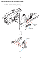
2-1. Video Light ······································································ 2-3
2-2. PD-180 Board ·································································· 2-4
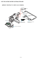
2-3. LCD Module ···································································· 2-5
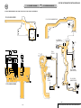
Service Position to Check PD-180 Board ······················· 2-5
2-4. Control Switch Block (PR-3000) ···································· 2-6
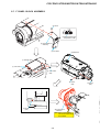
2-5. VF Lens (M) Assembly ··················································· 2-7
2-6. Cabinet (L) Assembly ······················································ 2-8
2-7. F Panel Block Assembly ·················································· 2-9
Service Position to Check SI-035 Board ······················· 2-10
2-8. SI-035 Board ································································· 2-11
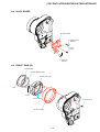
2-9. Front Ring (30) ······························································ 2-11
2-10. Cabinet (R) Block Assembly ········································· 2-12
Service Position to Check the Camera Section ············· 2-12
2-11. Control Switch Block (CF-3000) ·································· 2-13
2-12. Hinge (30) Assembly ····················································· 2-14
2-13. Control Switch Block (FK-3000) ·································· 2-15
2-14. EVF Block Assembly ···················································· 2-15
Service Position to Check VC-303 Board (Side A) ······· 2-16
2-15. Battery Panel Block Assembly ······································ 2-17
2-16. Control Switch Block (SS-3000) ··································· 2-18
2-17. Lens Block Assembly ···················································· 2-18
2-18. FP-576 Flexible Board ·················································· 2-19
2-19. Cabinet (L) Section ······················································· 2-20
2-20. VC-303 Board ······························································· 2-20
Service Position to Check VC-303 Board (Side B) ······· 2-21
Service Position to Check the Mechanism Deck ··········· 2-22
2-21. Mechanism Deck Block ················································ 2-23
2-22. Circuit Boards Location ················································ 2-24
2-23. Flexible Boards Location ·············································· 2-25
3.
BLOCK DIAGRAMS
3-1.
3-2.
3-3.
3-4.
3-5.
3-6.
3-7.
Overall Block Diagram (1/5) ··········································· 3-1
Overall Block Diagram (2/5) ··········································· 3-3
Overall Block Diagram (3/5) ··········································· 3-5
Overall Block Diagram (4/5) ··········································· 3-7
Overall Block Diagram (5/5) ··········································· 3-9
Power Block Diagram (1/2) ··········································· 3-11
Power Block Diagram (2/2) ··········································· 3-13
Title
Page
PRINTED WIRING BOARDS AND
SCHEMATIC DIAGRAMS
4-1. Frame Schematic Diagrams
Frame Schematic Diagram (1/2) ····································· 4-1
Frame Schematic Diagram (2/2) ····································· 4-3
4-2. Schematic Diagrams ························································ 4-5
CD-409 (CCD IMAGER) ················································ 4-7
VC-303 (1/11)
(A/D CONVERTER, TIMING GENERATOR) ·············· 4-9
VC-303 (2/11)
(CAMERA/VTR PROCESS, LENS CONTROL) ········ 4-11
VC-303 (3/11) (LENS DRIVE) ···································· 4-13
VC-303 (4/11) (REC/PB AMP) ···································· 4-15
VC-303 (5/11) (SERVO) ··············································· 4-17
VC-303 (6/11) (CAMERA/MECHA CONTROL) ······· 4-19
VC-303 (7/11) (HI CONTROL) ···································· 4-21
VC-303 (8/11) (EVF DRIVE) ······································· 4-23
VC-303 (9/11) (AUDIO, VIDEO) ································· 4-25
VC-303 (10/11) (DC CONTROL) ································ 4-27
VC-303 (11/11) (CONNECTOR) ································· 4-29
PD-180 (1/2)
(RGB DRIVE, TIMING GENERATOR) ······················ 4-31
PD-180 (2/2) (BACKLIGHT DRIVE) ·························· 4-33
SI-035 (STEADYSHOT, MIC), FP-569 FLEXIBLE ···· 4-35
FP-576 FLEXIBLE ······················································· 4-37
LS-057 (S/T REEL SENSOR), FP-228, FP-299,
FP-300, FP-301, FP-302 FLEXIBLE ···························· 4-38
CF-3000, FK-3000 (CONTROL SWITCH BLOCK) ··· 4-39
SS-3000, PR-3000 (CONTROL SWITCH BLOCK) ···· 4-41
4-3. Printed Wiring Boards ··················································· 4-43
CD-409 ·········································································· 4-45
VC-303 ·········································································· 4-47
PD-180 ··········································································· 4-51
SI-035 ············································································ 4-55
LS-057, FP-228, FP-299, FP-300, FP-301,
FP-302, FP-569, FP-576 FLEXIBLE ···························· 4-57
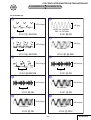
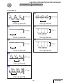
4-4. Waveforms ····································································· 4-61
4-5. Mounted Parts Location ················································ 4-68
5.
REPAIR PARTS LIST
5-1.
Exploded Views ···························································· 5-2
5-1-1. Overall Assembly ·························································· 5-2
5-1-2. F Panel Block Assembly ··············································· 5-3
5-1-3. Lens Block Assembly ··················································· 5-4
5-1-4. LCD Block Assembly ··················································· 5-5
5-1-5. Cabinet (R) Block Assembly ········································ 5-6
5-1-6. EVF Block Assembly ···················································· 5-7
5-1-7. Battery Panel Block Assembly ······································ 5-8
5-1-8. MD Frame Block ·························································· 5-9
5-1-9. Cassette Compartment Assembly, Drum Assembly ··· 5-10
5-1-10. LS Chassis Block Assembly ······································· 5-11
5-1-11. Mechanical Chassis Block Assembly-1 ······················ 5-12
5-1-12. Mechanical Chassis Block Assembly-2 ······················ 5-13
5-2.
Electrical Parts List ····················································· 5-14
—5—