1
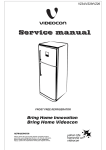
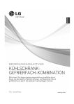
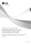
http://biz.lgservice.com
REFRIGERATOR
SERVICE MANUAL
CAUTION
BEFORE SERVICING THE UNIT, READ THE "SAFETY
PRECAUTIONS" IN THIS MANUAL.
Ref. No.
GB7143**AV
GB7143**BV
MODEL :
Ref. No.
GB7143**GZ
GB7143**HZ
Ref. No.
GB7143**RZ
GB7138**XZ
Ref. No.
GB7143**RZ
GB7138**XZ
COLOR :
CONTENTS
SAFETY PRECAUTIONS ....................................................................................................................................................... 2
SERVICING PRECAUTIONS ...................................................................................................................................................3
SPECIFICATIONS ................................................................................................................ ................................................4-5
PARTS IDENTIFICATION .....................................................................................................................................................6-9
INSTRUCTIONS FOR REVERSING DOOR SWING ........................................................................................................10-12
DISASSEMBLY .................................................................................................................................................................13-15
DOOR ................................................................................................................................................................................13
DOOR SWITCH .................................................................................................................................................................13
REFRIGERATOR ROOM LAMP ........................................................................................................................................13
FAN AND FAN MOTOR .....................................................................................................................................................14
DEFROST CONTROL ASSEMBLY ...................................................................................................................................14
FRIDGE HEATER, SHEATH .............................................................................................................................................15
FREEZER HEATER, SHEATH ..........................................................................................................................................15
CASE ASSEMBLY, PUMP DISASSEMBLY ......................................................................................................................16
COMPRESSOR .................................................................................................................................................................17-22
INVERTER LINEAR COMPRESSOR ...........................................................................................................................17-22
HEAVY REPAIR METHOD OF REFRIGERATOR BY APPLICATION OF REFRIGERANT ................................................23
OUTLINE ............................................................................................................................................................................23
HEAVY REPAIR SVC METHOD ..................................................................................................................................24-29
CIRCUIT DIAGRAM ...............................................................................................................................................................30
TROUBLESHOOTING (MECHANICAl PART) .................................................................................................................31-35
ANOTHER ELECTRIC COMPONENTS ............................................................................................................................31
SERVICE DIAGNOSIS CHART .........................................................................................................................................32
REFRIGERATING CYCLE ...........................................................................................................................................33-35
MICOM FUNCTION & PCB CIRCUIT EXPLANATION ....................................................................................................36-43
MICOM ERROR CODE ..........................................................................................................................................................43
PCB PICTURE ..................................................................................................................................................................44-45
TROUBLESHOOTING WITH ERROR DISPLAY .............................................................................................................46-56
TROUBLESHOOTING WITHOUT ERROR DISPLAY ......................................................................................................57-65
REFERENCE ..................................................................................................................... ...............................................66-70
EXPLODED VIEW &REPLACEMENT PARTS LIST ........................................................................................................71-83
SAFETY PRECAUTIONS
Please read the following instructions before servicing your
refrigerator.
1. Check the set for electric losses.
2. Unplug prior to servcing to prevent electric shock.
3. Whenever testing with power on, wear rubber gloves to
prevent electric shock.
4. If you use any kind of appliance, check regular current,
voltage and capacity.
5. Don't touch metal products in the freezer with wet
hands. This may cause frostbite.
6. Prevent water from following onto electric elements in
the mechanical parts.
7. When standing up after having checked the lower
section of the refrigerator with the upper door open,
move with care to avoid hitting the upper door.
8. When tilting the set, remove any materials on the set,
especially the thin plates(ex. Glass shelf or books.)
9. When servicing the evaporator, wear cotton gloves.
This is to prevent injuries from the sharp evaporator fins.
10. Leave the disassembly of the refrigerating cycle to a
specialized service center. The gas inside the circuit
may pollute the environment.
11. When you discharge the refrigerant, wear the protective
safety glasses or goggle for eye safety.
12. When you repair the cycle system in refrigerator, the
work area is well ventilated.
Especially if the refrigerant is R600a, there are no fire or
heat sources. (No smoking)
-2-
SERVICING PRECAUTIONS
Features of refrigerant (R600a)
• Achromatic and odor less gas.
• Flammable gas and the ignition (explosion) at 494°C.
• Upper/lower explosion limit: 1.8%~8.4%/Vol.
Features of the R600a refrigerator
• Charging of 60% refrigerant compared with a R134a model.
• The suction pressure is below 1bar (abs) during the operation.
• Because of its low suction pressure, the external air may flow
in the cycle system when the refrigerant leak, and it causes
malfunction in the compressor.
• The displacement of compressor using R600a must be at
least 1.7 times larger than that of R134a.
• Any type of dryer is applicable (XH-5, 7, 9).
• The EVAPORATOR or any other cycle part that has welding
joint is hidden in the foam. (If not hidden inside, the whole
electric parts must be tested with the LEAKAGE TEST
according to the IEC Standard.)
• The compressor has label of the refrigerant R600a.
• Only the SVC man must have an access to the system.
After the refrigerant (R600a) is completely discharged, repair
any defective parts and replace the dryer. At any case you
must use the LOKRING for connecting or replacing any part in
the cycle (No Fire, No Welding). Connect the Schrader valve
to pump with the coupler. And then turn the pump on for
vacuum state (Figure 3). Let the pump run until the lowpressure gauge indicates the vacuum (gauge pressure 0,
absolute pressure -1atm or -760mmHg). Recommended
vacuum time is 30 min. Charge the N2 gas in order to check for
leakage from welding points and the LOKRING. If leakages
are found, repair the defects and repeat the vacuum process.
Figure 3
Installation place
After the system is completely vacuumed, fill it with the
refrigerant R600a up to what has been specified at your
refrigerator Name Plate. The amount of refrigerant (R600a)
must be precisely measured within the error of ±2g by an
electron scale (Figure 4).
Utilities
If you use the manifold connected with both the refrigerant
(R600a) cylinder and the vacuum pump simultaneously, make
sure the pump valve is closed (Figure 5).
• Must be well ventilated.
• Must be 20 m3 or larger.
• Must be no-smoking area.
• No ignitable factors must be present.
• Refrigerant cylinder (MAX NET 300g)
• Manometer
• Vacuum pump (600 /min)
• Piercing Clamp
• Quick coupler
• Hoses (5m-1EA, 1m-3EA)
• LOKRING
• Portable Leakage detector (3g/year )
• Nitrogen cylinder (for leakage test)
• Concentration gauge
Make sure before Servicing
• Refrigerant
Confirm the refrigerant by checking Name Plate and the label
on the compressor, after opening the COVER ASSEMBLY,
BACK-M/C.
• If the refrigerant is R600a, you must not weld or apply a heat
source.
Figure 4
Air Recharging in Compressor
Before refilling the refrigerant, you must perform the test
according to Chapter 5 (TROUBLESHOOTING CHART). When
the defects are found, you must discharge the residual
refrigerant (R600a) in the outdoor. For discharging the
refrigerant R600a, break the narrow portion of tube extension
by hand or with a pipe cutter as shown in Figure 1. Leave it for
30min in outside to stabilize the pressure with ambient. Then,
check the pressure by piercing the dryer part with piercing
pliers. If the refrigerant is not completely discharged, let the
refrigerator alone for more 30min in outside.
Figure 1
Figure 2
Attach the service tube installed with a Schrader valve (oneway valve) by using the LOKRING (Figure 2). Then, connect
the Schrader valve (one-way valve) to the pump that is
connected to the discharging hose leading to the outside.
When discharging the residual refrigerant, repeat 3 cycle that
includes 3min of the pump running->pump off->30sec of the
compressor running.
-3-
Figure 5
Connect the charging hose (that is connected to the
refrigerant (R600a) cylinder) to the Schrader valve installed
on the service tube. Then, charge the refrigerant (R600a) by
controlling the Throttle valve. When you do so, do not fully
open the Throttle valve because it may make damage to the
compressor. Gradually charge the refrigerant (R600a) by
changing open and close the Throttle Valve (5g at each time).
The charging hose must use a one-way valve to prevent the
refrigerant refluence. Close the Schrader valve cap after the
refrigerant (R600a) is completely recharged.
After you completely recharge the refrigerant (R600a),
perform the leakage test by using a portable leakage detector
or soapy water. Test the low pressure (suction) parts in
compressor off time and high pressure parts in compressor
on time. If the leakages are found, restart from the refrigerant
(R600a) discharging process and repairs defects of leaks.
After the leakage test, check the temperature of each parts of
the cycle. Check with hands if the CONDENSER and the
case (HOT-LINE pipe) that is contacted to the door gasket
are warm. Confirm that frost is uniform distributed on the
surface of the EVAPORATOR.
SPECIFICATIONS
1. Ref. No: GB7143*****
ITEMS
DIMENSIONS (mm)
GB7143**(A/B)V
GB7143**(G/H)Z
GB7143**(G/H)W
73g
73g
71g
-
-
595(W) X 2010(H) X 671(D)
595(W) X 1850(H) X 671(D)
NET WEIGHT
-
COOLING SYSTEM
Fan Cooling
TEMPERATURE CONTROL
Micom Control
DEFROSTING SYSTEM
Full Automatic
Heater Defrost
DEFROSTING DEVICE
Heater, Sheath
Heater, L-Cord
REFRIGERANT WEIGHT
LUBRICATION OIL
R600a
FREOL 60MT 310 cc
-
FREOL 55MT 180 cc
COMPRESSOR
PTC Starting Type
EVAPORATOR
Pin Tube Type
CONDENSER
Wire Condenser
3EA
Removable Glass Shelf
3EA
3EA
-
-
Bottle Rack (1EA)
Vita, LED(1EA)
REFRIGERATOR
Cover, TV (1EA)
COMPARTMENT
Rail (2EA)
Magic Crisper (1EA)
Vegetable Drawer (1EA)
OPTI-Zone (1EA)
Egg Tray
Dairy Corner
DOOR BASKET
Basket Door
Basket
Water Tank
Tray Drawer (3EA)
Ice bin (1EA)
FREEZER
Twist Ice Maker Kit (1EA)
COMPARTMENT
Auto Ice Maker
-
Guide, Rail (1EA)
Wire Shelf (2EA)
-4-
2. Ref. No: GB71(43/38)*****
ITEMS
DIMENSIONS (mm)
GB71(43/38)**(R/X)W GB71(43/38)**(R/X)Z
GB71(43/38)**(P/V)W
595(W) X 2010(H) X 671(D)
595(W) X 1850(H) X 671(D)
NET WEIGHT
-
COOLING SYSTEM
Fan Cooling
TEMPERATURE CONTROL
Micom Control
DEFROSTING SYSTEM
Full Automatic
Heater Defrost
DEFROSTING DEVICE
Heater, Sheath
-
Heater, L-Cord
REFRIGERANT WEIGHT
LUBRICATION OIL
71g
R600a
73g
71g
-
-
3EA or 2EA
3EA or 2EA
3EA or 2EA
-
-
-
FREOL 60MT 310 cc
-
FREOL 55MT 180 cc
COMPRESSOR
PTC Starting Type
EVAPORATOR
Pin Tube Type
CONDENSER
Wire Condenser
Removable Glass Shelf
Bottle Rack (1EA)
Vita, LED(1EA)
REFRIGERATOR
Cover, TV (1EA)
COMPARTMENT
Rail (2EA)
-
-
-
Magic Crisper (1EA)
-
-
-
2EA
2EA
2EA
-
-
-
-
-
-
-
-
-
-
Vegetable Drawer (1EA)
OPTI-Zone (1EA)
Egg Tray
Dairy Corner
DOOR BASKET
Basket Door
Basket
Water Tank
Tray Drawer (3EA)
Ice bin (1EA)
FREEZER
Twist Ice Maker Kit (1EA)
COMPARTMENT
Auto Ice Maker
Guide, Rail (1EA)
Wire Shelf (2EA)
-5-
-
PARTS IDENTIFICATION
GB7143**(A/B)V
Lamp
Egg Tray
Dairy Corner
Bottle Rack
Basket Door
Removable
Glass Shelf
Water Pump
(Optional)
Water Tank
(Optional)
Water Tank
Basket Door
Vegetable Drawer
Used to keep fruits
and vegetables etc.
fresh and crisper
OPTI-Zone
(Optional)
Auto Twisting
Ice Maker
Ice Box
EZ Open Handle
(Optional)
Wire Shelf
Freezer
Compartment
Leveling Screw
-6-
GB7143**(G/H)W/Z
Lamp
Egg Tray
Dairy Corner
Bottle Rack
Basket Door
Removable
Glass Shelf
Water Pump
(Optional)
Water Tank
(Optional)
Basket Door
Vegetable Drawer
Used to keep fruits
and vegetables etc.
fresh and crisper
OPTI-Zone
(Optional)
Twist Ice Tray
Ice Box
EZ Open Handle
(Optional)
Wire Shelf
Freezer
Compartment
Leveling Screw
-7-
GB7143**PW, GB7143**R(W/Z)
Lamp
Egg Tray
Dairy Corner
Bottle Rack
Basket Door
Removable
Glass Shelf
Water Pump
(Optional)
Water Tank
(Optional)
Basket Door
Fresh 0 Zone
Vegetable Drawer
Used to keep fruits
and vegetables etc.
fresh and crisper
Twist Ice Tray
Ice Box
EZ Open Handle
(Optional)
Wire Shelf
Freezer
Compartment
Leveling Screw
-8-
GB7138**VW, GB7138**X(W/Z)
Lamp
Egg Tray
Dairy Corner
Removable
Glass Shelf
Basket Door
Water Pump
(Optional)
Water Tank
(Optional)
Bottle Rack
Basket Door
Fresh 0 Zone
Vegetable Drawer
Used to keep fruits
and vegetables etc.
fresh and crisper
Twist Ice Tray
Ice Box
EZ Open Handle
(Optional)
Wire Shelf
Freezer
Compartment
Leveling Screw
-9-
INSTRUCTIONS FOR REVERSING DOOR SWING
This refrigerator allows the owner to change the door swing if desired. The hinging of the doors can be changed
to the opposite side anytime you wish.
When reversing the door swing :
Read the instructions all the way through before starting.
Handle parts carefully to avoid scratching paint.
Set screws down by their related parts to avoid using them in the wrong places.
Provide a non-scratching work surface for the doors.
IMPORTANT
Once you begin, do not move the cabinet until door-swing reversal is completed.
These instructions are for changing the hinges from the right side to the left side-if you ever want to change the hinges back
to the right side, follow these same instructions and reverse all references to left and right.
Befor Removing the Doors, empty and Remove all the Door Baskets of both Refrigerator/Freezer Doors, including the Bank
Dairy. Close both doors before removing hinge pins.
Warning
Electric Shock Hazard
Disconnect electrical supply to refrigerator before installing. Failure to do so could result in death or serious injury.
Caution :
Do not let either door drop to the floor. Doing so could damage the Door Stop.
- 10 -
1) Remove screws(3) after removing a CAP(2) from the side
of the refrigerator room HANDLE(1).
The freezer room HANDLE(5) may be also disassembled in
a same may as the refrigerator room HANDLE(1).
(4)
(3)
(2)
(1)
(3)
(2)
(4)
(5)
$
2) Remove the screws(6) in the DECO COVER(7).
Remove the DECO COVER(7) and move the COVER
HINGE(8) to side of DECO COVER(7). Disassemble the
Housing Connector(9) inside of the DECO COVER(7).
$
%
'
&
3) Remove the screws(10) in the COVER-PWB(11), and
remove the COVER-PWB(11).
!
4) Remove the screws(12) in the TOP COVER FRONT(13)
and remove the TOP COVER FRONT (13).
"
5) Remove the HOLDER CORD (14) placed in right and insert
it to center. And then move COVER FRONT(16).
Take out the HOLDER CORD(spare) (15) and to place in
the center of TOP COVER FRONT(13), and insert to the
left side.
- 11 -
$
#
6) Take out the LEAD WIRE(17) assembly from the TOP
COVER FRONT(13) and assemble it on left side.
7) Remove bolts(18) securing HINGE-U(19). Unscrew of the
hinge pin(20).
Place HINGE-U and seat hinge upside down and apply
them to left side of the refrigerator.
NOTE: Seat hinge to be placed under the HINGEU(19).
8) Remove bolts(22) securing HINGEC(23) and then remove
HINGE-C(23).
Remove the freezer door. Move in left side of the
refrigerator CAP(24). Move to left side of the refrigerator
door BRACKET DOOR(25) and screw(26).
9) Remove Bolts(27), HINGE-L(28), Stopper(29), (30) and
Lavel(31).
Use the new HINGE-L in Drawer and attach a label to a
screw Hole.
(32)
(27)
(29)
(30)
10) Assemble the HINGE-L
Freezer Door
HINGE-C(23)
Refrigerator Door
HINGE-U(19)
TOP COVER FRONT(13)
COVER PWB(11)
Connect the Housing Connector(9)
DECO COVER(7)
HANDLE(1) (5)
Note:
Reversing the doors is not covered by the warranty.
- 12 -
DISASSEMBLY
1. DOOR
3. REFRIGERATOR ROOM LAMP
Freezer Door
1) Refer to previous chapter "Instruction for Reversing
Door Swing".
2) Pull out the Door Gasket to remover from the Door
Foam Assembly, F.
GASKET
1) Unplug the power cork the outlet.
2) Remove all of the fridge compartment,
(Involved removable glass shelf, wine rack etc.)
3) Remove one screws in Case, Control Refrigerator.
4) Pull out the Grille Fan and Case, Control Refrigerator.
5) Disconnect the Housing of lead wire.
6) Replace new one.
7) Assembly in reverse order of disassembly.
8) Replacement LED must be the same specification as
original.
Figure 7
Figure 10
Refrigerator Door
Don’t touch the LED, in case of light on the long time.
Because it can be very hot.
LED capacity is MAX 8W (GB7138**** MODEL : 6W).
The LED will remain “ON” for 7minutes if the door is left
open and then it is “OFF” for safety.
(If you reopen the door, the lamp is “On”.)
1) Refer to previous chapter "Instruction for Reversing
Door Swing".
2) Pull out the Door Gasket to remove from the Door
Foam Assembly, R.
2. DOOR SWITCH
1) Unplug the power cord from the outlet.
2) Loosen six screws in upper part and disconnect Top
Cover Front.
3) Disconnect Lead Wire from switch.
4) Disengage hook behind the switch by pressing it with
hands.
Figure 9
- 13 -
4. FAN AND FAN MOTOR
2) Freezer
1) Fridge
1) Remove all of the freezer compartment,
(Involved wire shelf, ice maker)
2) Remove two screws in Grille Fan.
3) Pull out the Grille Fan and Shroud F.
4) Disconnect the Housing of lead wire.
5) Remove three screws in Grille Fan.
6) Separate Shroud, F to the Grille Fan.
7) Loose three screws fixed to the Bracket.
8) Pull out Bracket and then remove the Fan Motor
Assembly.
Fan Motor Assembly can’t separate.
1)
2)
3)
4)
5)
6)
Remove all of the Fridge compartment.
Remove one screw in Case Assembly,Control REF.
Pull out the Case Assembly, Control REF.
Disconnect the Housing of lead wire.
Loose five screws fixed to the Bracket.
Pull out Bracket and then remove the Fan Motor
Assembly.
FAN MOTOR
ASSEMBLY
BRACKET
HEATER,
SHEATH
SHROUD
Figure 11
5. DEFROST CONTROL ASSEMBLY
Defrost Control Assembly consists of Thermistor and Fuse,
Melting. Thermistor functions to defrost automatically and it
is attached to metal side of the Evaporator and senses
temperature.
Fuse, Melting is a kind of safety device for preventing
overheating of the Heater when defrosting.
At the temperature of 77 , it stops the emission of heat
from the Heater.
1) Pull out the Shroud, F after removing the Grille.
- Freezer
Pull out the Grille. - Fridge
2) Separate the connector connected with the Defrost
Control Assembly and replace new one.
Thermister
Fuse, Melting
Figure 12
- 14 -
6. FRIDGE HEATER, SHEATH
In this refrigerator, Heater, Sheath is used for defrosting
heater. During heating, the temperature of heater rises
about 150~200 . Therefore, be careful not to burn while
servicing.
1) After removing the Grille and Shroud, separate the
Heater, Sheath by disconnecting the connectors.
2) Exchanged Heater, Sheath and connected the housing.
Heater, Sheath
7. FREEZER HEATER, SHEATH
In this refrigerator, Heater, Sheath is used for defrosting
heater. During heating, the temperature of heater rises
about 300~350 . Therefore, be careful not to burn while
servicing.
1) After removing the Grille and Shroud, separate the
Heater, Sheath by disconnecting the connectors.
2) Exchanged Heater, Sheath and connected the housing.
Heater, Sheath
Figure 13
- 15 -
8. CASE ASSEMBLY PUMP DISASSEMBLY
Remove the basket over
the case pump.
Disassemble Screw.
The dial rotated with open.
Pull up the case pump.
Remove the water tank.
Pull out each other and
Disconnect the tubes.
Check these when water is not supplied:
1) Check whether water is in the water tank.
2) Check whether you can hear the sound of pump working, when you push the dispenser button.
3) Check each connecting point of tubes.
(Water tank assembly, Case pump assembly)
Notice!
Pump may cause noise while water is being dispensed. This is due to remove the water inside tube for sanitation.
When long period dose not use or the first use, you have to fill the water tank with over 1L water.
Caution :
Do not use other beverage (milk, juice, carbonated beverage etc) than potable water.
Especially beverage including grain must not be used (may result in failure).
- 16 -
COMPRESSOR
1. Inverter Linear Compressor
Check for defect of the inverter linear compressor in following orders:
1) Method to Measure Compressor Winding Resistance
Normal Determination Criteria.
The compressor winding resistance can be determined as normal if resistance values show the values as described in
below figure when measuring resistance values of the harness (connected with compressor) to connect.
Connect201(CON201) of the main PWB as shown in below figure.
Defect Determination Criteria
Check connection status of the Compressor Connection Harness-P(Lead Wire) which is located at the M/C room where
resistance values measured at the CON201 Housing are shown as infinite or several hundred . Separate connecting
wires of the M/C room (A-point in Figure) and then measure resistance values at the connecting wires again. The
compressor can be determined as normal if resistance values are shown as standard resistance value. Check connection
status of a harness.
Defect at M/C room connection contact or CON201 Housing contact, short-circuit of harness)
Where resistance values measured at A-point are also shown as infinite or several hundred , disassemble a cover PTC
of the compressor terminal and check the terminal connecting status at the B-point in Figure.
Where there is no failure in the wiring status and resistance values are shown as infinite or several hundred , it may be
determined as defect of compressor.
Since if there is no failure in resistance values of the compressor, it may be defective Main PWB, replace the Main PCB
and check for normal operation of the compressor.
When determining any defect through resistance measuring, it can be determined as normal if resistance values show as
descried in the below figure by measuring
power and
common terminal or
full power and
common terminal.
However, resistance values are measured when measuring
power and
full but measuring is meaningless since they
cannot become criteria for determining defect (measuring not required).
Caution
1. Be sure to powering off the refrigerator and measure after several minutes has passed.
2. If not accurately measuring resistance, wrong determination may be guided. (Difference of resistance value of several W
or so may occur.)
CON201
Multi
Tester
Multi
Tester
Po : Power
Co : Common
N/C : Open terminal
Resistance
OLP
FC75LANE
Capacitor Spec.
5%
550V, 10uF
Multi
Tester
Dead Short Check
Because of ambient temperature or operating situations;
the values shown can have a slight devlation.
Earth
Multi
Tester
Hermetic terminal
- 17 -
6~8
2) Method to Determine Defect of Inverter Linear Drive
Determination of Comp Operation
Separate the back cover at the rear of refrigerator and determine for possible operation while touching the compressor with
the hands with insulation gloves worn.
Comp Operation
- Determine possible trip by checking operation status if cold air comes out after opening the doors of the R-Room.
Protective Logic (Trip)
- To protect the compressor from abnormal operation, this logic is used to temporally stop the refrigerator when abnormal
operation occurs and to re-operate it after abnormal signal disappears.
Compressor protection Logic Table
App.
Requirement
Waiting Time
The number of LED
blinking
Stroke Trip
E-Inv.
Piston overruns the designed range.
1’ 00’’
2
Locked Piston Trip
E-Inv.
Piston is locked.
2’ 30’’
5
Current Trip
E-Inv.
Current overruns the designed range
6’ 00’’
6
IPM Fault
E-Inv.
20’’
7
IPM pin 14 output voltage = low
(IPM Short, High current input, or low
voltage input)
If LED of PCB is blinking, Refer to next page.
- 18 -
3) LED blinks two times, then repeats (Stroke Trip)
Purpose: Prevent abnormally long piston strokes.
Case 1. If compressor doesn’t work and LED blinks
- Cause: Possibly harness from compressor to PCB might be defective.
Case 2. If compressor works intermittently and LED blinks
- Cause: Condenser Fan or Freezer Fan is not running. Sealed system problem such as moisture restriction, restriction at
capillary tube or refrigerant leak.
Logic: Compressor is forced to off and then tries to restart after 1 minute.
Protection
logic
Check B
Blink 2 times
(Stroke Trip)
Check B2
Compressor
Doesn t work
N
Fix Harness
Y
Harness
Connecting
Check C
Y
Compressor
Works
Intermittently
Y
Replace
Driver PCB
N
OK
Fix
Cycle
NG
Cycle
Check E
Repeat
Check Procedure
N
Y
Stroke Trip
Occur?
Capacitor
Spec.
Check C
N
Replace
Capacitor
N
Replace
Compressor
Y
Reset
Power
Compressor
Damage
Check C
Y
- 19 -
4) LED blinks five times, then repeats (Locked Piston)
Purpose: To detect locked piston
Cause: Lack of oil to the cylinder, cylinder or piston damaged and or restricted discharge.
A Locked Piston can also be caused by foreign materials inside the compressor.
Logic: Compressor is forced off and tries to restart within 2.5 minutes.
Protection
logic
Check B
Blink 5 times
(Lock Piston Trip)
Check B3
Replace
Compressor
N
Compressor
Doesn’t work
Reset
Power
Compressor
Doesn’t work
N
Repeat
Check Procedure
- 20 -
Y
Hi side
restriction
Y
Sealed
system
Repair
5) LED blinks six times, then repeats (Current Trip)
Purpose: Prevent over-current (overload protect)
Cause: Ambient temperature is high (over 43 ) and/or refrigerator s condenser air movement is restricted.
Condenser Fan is stopped, restricted discharge line, compressor is damaged, or IPM device is defective.
Logic: Compressor is forced off and tries to restart after 2.5 minutes.
Protection
logic
Check B
Blink 6 time
(Current Trip)
Check B4
Compressor
Intermittently
works
Y
Replace
Driver
PCB
Fix
Cycle
Cycle
Check E
Repeat
Check
Procedure
NG
Replace
Capacitor
Y
N
Y
NG
Capacitor
Spec.
Check C2
IPM
Check B5
Y
Y
N
Current trip
Occur?
Reset
Power
Compressor
Damage
Check C3
Y
- 21 -
NG
Replace
Compressor
6) LED blinks seven times, then repeats (IPM Fault)
Purpose: Prevent high current due to IPM Short
Cause: Damaged IPM (Dead Short)
Test for a dead short at Point A with a VOM.
Logic: Compressor is forced off and tries to restart in 2.5 minutes.
A
Protection
logic
Check B
Blink 7 times
(Lock Piston Trip)
Check B5
Compressor
Doesn’t work
Y
Check IPM
visual inspection
(turn off)
Short
Test
Point A
N
N
Replace
Drive PCB
Y
Repeat
Check Procedure
Compressor
Damage
Check C3
Power
Reset
Y
NG
- 22 -
Replace
Compressor
Heavy Repair Method of Refrigerator by Application of Refrigerant
1. Outline
1) Checkpoints before Heavy Repair
Open the Cover ASM, Back-M/C of refrigerator and check the type of refrigerant indicated on a compressor before starting
work.A yellow label is adhered to the compressor for the refrigerator using R600a as refrigerant.
2) Features of R600a Refrigerant
Non-polar natural gas refrigerant (CH(CH3)3)
Since R600a is same series as butane gas, there is danger of fire when discharged into air at appropriate concentration
(extreme handling is required for heavy repair of cycle).
Explosion concentration: .8% ~ 8.4%/Vol.
Burning temperature: 494°C
3) Features of R600a Refrigerant
With refrigerant quantity of 60% or so for the refrigerator using R134a as refrigerant
Large vacuum level at suction pressure (at low pressure side)
COMP capacity of the refrigerator using R609a as refrigerant is large by 1.7 times than that of the refrigerator using
R134a.
Labels as in Figure are displayed at the compressor of a refrigerant for R600a and the back plate of refrigerator.
Insulation Blowing Gas : Cyclopentane
15mm
[Warning sign according to ISO 3864]
4) Location and Environment for Heavy Repair
Check that drafting and air ventilation are well done at a working area and perform work after making drafting and air
ventilation smooth (use refrigerant return bag indoors).
Check that there are fire appliances or heating source around the working area and then remove them before work.
Since R600a refrigerant is very inflammable, they should not be discharged indoors.
Be sure to follow heavy repair SVC procedures during work.
5) Heave Repair Work Tool
R600a refrigerant
Bombe
Pinch Pliers
Refrigerant Discharge Hose
Refrigerant Return Bag
Vacuum Pump
Handy Welding Machine
Charging Tube
Leakage Tester
Drier
- 23 -
2. Heavy Repair SVC Method
For the heaver repair of R600a type of refrigerator, perform work according to following SVC method.
1) Returnof Refrigerator Refrigerant
Required equipment: Pinch pliers, refrigerant discharging hose, refrigerant returnbag
Take power cords out and remove power between 6sec through 12sec after powering ON to open all both sides of 3way
valve.
Leave doors of a refrigerator so that they are not closed.
Connect pinch pliers with a refrigerant discharging hose.
Place the outlet of a refrigerant discharging hose outside.
(Remove fire appliances or heating sources near a refrigerant discharging hose.)
Always use a refrigerant returnbag for working at the contained space.
Bore the charging pipe of a compressor with pinch pliers.
(Remove fire appliances or heating sources near a refrigerator.)
Perform refrigerant discharge for more than 7 minutes.
Suction Pipe
Discharge Pipe
Process Pipe
Refrigerant ReturnBag
Pinch Plier
- 24 -
2) Returnof Remained Refrigerant
Required equipment: Pinch pliers, hose for refrigerant recovery, vacuum pump
If refrigerant returntime of 7 minutes has passed, connect a vacuum pump at the ends of a refrigerant returnhose
outdoor. (Vacuum pump must operate outdoor.)
Operate a vacuum pump in order to returnrefrigerant remained in the pipe.
Vacuum working time should be for more than 10 minutes.
Suction Pipe
Discharge Pipe
Process Pipe
Vacuum Pump
Pinch Plier
Discharge refrigerant
outside using window or door.
3) Welding Repair Step
Required equipment: Simple welding machine
Remove pinch pliers if remaining refrigerant returnis completed.
Cut the front part of a process pipe with a cutter. (Check that remaining refrigerant comes out.)
Perform welding work such as replacement of compressor and dryer, or repair of leakage part. (Be cautious of fire during
welding work.)
- 25 -
4) Charging Tube Connection Step
Required equipment: Charging tube, simple welding machine
Remove a charging pipe to recharge R600a refrigerant after completing work, and then connect a charging tube with
welding
Suction Pipe
Charging Tube
Discharge Pipe
5) Vacuum Air Removal
Required equipment: Vacuum pump
Connect a vacuum pump to a charging tube to perform vacuum cycle.
Vacuum work should be performed for an hour. (If vacuum time is short, normal cooling performance may not be exerted
due to failure of cooling cycle.)
- 26 -
6) Refrigerant Charging
Required equipment: Bombe, R600a refrigerant (73g)
Firstly remove fire appliances and heating source for performing work when charging scaled refrigerant. (Do not spray
refrigerant indoor.)
Measure the accurate quantity (73g) of refrigerant to charge it into a Bombe.
Make the Bomber as vacuum status to charge refrigerant.
(If there is air or moisture in a Bombe, it may give effect on performance of a cooling cycle.)
Please manage refrigerant quantity as 73g 1. Differently from R134a, R600a gives much effect on cooling performance
depending on change of refrigerant quantity.
Refrigerant quantity = Weight after charging - Weight before charging (weight of vacuumed Bombe)
Connect Bombe with a charging tube to charge refrigerant.
Turn on power of refrigerator to operate a compressor.
Measure Bombe weight after 5 through 10 minutes to check remained refrigerant quantity to complete charging of
refrigerant.
(After charging refrigerant, never perform welding work or work using fire appliances.)
Suction Pipe
Charging Tube
Discharge Pipe
7) Leak Inspection and Cycle Check
Required equipment: Leakage checking machine (foam and leakage inspection machine)
Check for leakage by using form or a leakage inspection machine at the worked part if charging of refrigerant is
completed.
Check for leakage at the low pressure part with the compressor stopped, and check at the high pressure part with the
compressor being operating.
If leakage is detected, proceed to repair according to repair process again starting from “2-1. Returnof Refrigerator
Refrigerant”.
(Never perform welding work or work using fire appliances.)
Check that heat remains at a discharge pipe or condenser with the hands if leakage check is completed. If heat remains,
the cooling cycle is normal.
(Take care since a discharge pipe may be hot.)
- 27 -
8) Failure Checking Procedures
Check of rotation
of COMP
Check of cooler
at F-Room,
R-Room
Surface of
cooler is cold.
Normal
Somewhat cold
Moisture clogged
Leakage of
3way valve
Surface of
cooler is cold.
Clogged cycle
Clogged
capillary tube
Leakage of
3way valve
Poor operation
of 3way valve
Non-insertion of
valve housing
Short-circuit of
valve L/wire
Defect or
shortage of valve
Defect or
shortage of PCB
Leakage of
refrigerant
Leakage of
welding part
Leakage
of radiator
- 28 -
Check of
leakage part
9) Cautions in Heavy Repair Service
Special caution should be taken since fire may occur for welding work since refrigerant may remain as it is at the high
pressure side even after vacuum air-discharge in relation with cycle clogging. Take power cords out and remove power
between 6sec - 12sec after powering on in order to open both sides of 3way valve in the step of refrigerant recovery. If both
sides of 3way valve will not be opened, fire may occur during welding work since refrigerant may remain during the cycle. To
prevent moisture clogging, always replace dryer together during heavy repair of refrigerator.
3-Way Valve Service
Since 3-way valve controls refrigerant with an inner plastic
damper, defect may occur because the plastic damper is
deteriorated and welding heat is delivered to a pipe during
welding for repair and replacement of the valve welding
part.
So perform service in following service method.
1) Replace 3wasy valve ASSY where refrigerant leakage
occurs at the joint pipe ( , ,
part) connected with the
service valve of valve welding part.
(For unavoidable welding, wrap the body part of valve with
a water towel so that delivery of welding heat is minimized
(100°C or less).
2) Service in replacement of valve (valve failure)
Perform service in the same method as above.
3) Other cautions
Body
Dryer side
R-Room<Sky-blue>
F-Room
(1)Pipe for capillary tube should be welded through insertion by 20+3-3mm. (For preventing clogging during welding)
(2)Take care since inner ejecting objects may be damaged if falling a valve or giving a strong shock. (Poor operation and
leakage quantity may be increased due to damage of inner parts.)
(3)Entirely remove and check ice formation which occurred in Eva before or after improvement work for non-insertion of
3-way valve housing, defect or shortage of goods, defective welding.
- 29 -
CIRCUIT DIAGRAM
- 30 -
TROUBLESHOOTING (Mechanical Part)
1. ANOTHER ELECTRIC COMPONENTS
Cooling is impossible
Compressor
doesn't run.
Check if current flows to
the following
components.
Cause.
a. Thermistor
Poor contacting.
b. Starting devices
Shorted or broken.
c. OLP
Poor contacting
or shorted.
d. Compressor coil
Coil shorted.
e. Circuit Parts
Poor contacting
or shorted.
Running state of
Compressor is poor.
Replace each
component.
Check a starting
voltage.
Low voltage.
Raise the voltage.
Check if current flows
to starting devices.
Poor contacting and
broken.
Replace each
component.
Check current flowing
in sub-coil of
Compressor.
Shorted.
Check capacity of
OLP.
Lack of capacity.
The items described
above are normal.
Coil of motor
Compressor.
Check current flowing
in SWITCH, DOOR.
Poor contacting.
Replace the
compressor.
Cooling ability is poor
Fan motor doesn't run.
Replace each
component.
Check current flowing
in the MOTOR[MECH],
FAN.
Much frost are sticked
to the EVAPORATOR.
Coil is shorted.
Check current flowing
of the following
components.
• THERMISTOR
• FUSE, MELTING
Check current flowing
of the following
components.
• HEATER, SHEATH
- 31 -
Shorted.
Replace each
component.
Defect on Heater,
Sheath
Replace the Heater,
Sheath
2. SERVICE DIAGNOSIS CHART
COMPLAINT
POINTS TO BE CHECKED
REMEDY
Cooling is
impossible.
Is the power cord unplugged from the outlet?
Check if the power switch is set to OFF.
Check if the fuse of power switch is shorted.
Measure the voltage of power outlet.
Plug to the outlet.
Set the switch to ON.
Replace a regular fuse.
If voltage is low, wire newly.
Cooling ability is
poor.
Check if the set is placed close to wall.
Check if the set is placed close to stove, gas
cooker and direct rays.
Is the ambient temperature high or the room
door closed?
Check if put in is hot.
Did you open the door of the set too often or
check if the door is closed up?
Check if the Damper Control is set to "coldposition".
Place the set with the space of about 10cm.
Place the set apart from these heat
appliances.
Make the ambient temperature below.
Foods in the
Refrigerator are
frozen.
Is foods placed in cooling air outlet?
Check if the control is set to "cold-position".
Is the ambient temperature below 5°C?
Place foods in high temperature section.
(Front Part)
Set the control to "mid-position".
Set the control to "warm-position".
Dew or ice forms in
the chamber of the
set.
Is liquid food stored?
Check if put in is hot.
Did you open the door of the set too often or
check if the door is closed up.
Seal up liquid foods with wrap.
Put in foods after cooled down.
Don't open the door too often and close it
firmly.
Dew forms in the
Exterior Case.
Check if ambient temperature and humidity of
surroumcling air are high.
Wipe dew with a dry cloth. This occurrence
is solved naturally in low temperature and
humidity.
Fill up the gap.
Is there gap in the door packed?
Abnormal noise
generates.
To close the door is
not handy.
Are the set positioned in a firm and even
place?
Are any unnecessary objects set in the back
side of the set?
Check if the Tray Drip is not firmly fixed.
Check if the cover of mechanical room in
below and front side is taken out.
Adjust the Adjust Screw, and position in the
firm place.
Remove the objects.
Check if the door packing is dirty with filth
such as juice.
Is the set positioned in a firm and even place?
Clean the door packing.
Is too much food putted in the set?
Ice and foods smell
unpleasant.
Put in foods after cooled down.
Don't open the door too often and close it
firmly.
Set the control to mid-position.
Check if the inside of the set is dirty.
Did you keep smelly foods without wrapping?
It smells of plastic.
Fix it firmly on the original position.
Place the cover at the original position.
Position in the firm place and adjust the
Adjust Screw.
Keep foods not to reach the door.
Clean the inside of the set.
Wrap smelly foods.
The new products smells of plastic, but it is
eliminated after 1-2 weeks.
In addition to the items described left, refer to the followings to solve the complaint.
Check if dew forms in
the Freezer.
Defrosting is
poor.
Replace the Components of
defrosting circuit.
Check Refrigerating
Cycle.
The cycle is
faulty.
Repair the cycle.
Check the
Damper Control
The operation of
the Damper
Control is poor.
Replace the Damper Control
- 32 -
3. REFRIGERATING CYCLE
Troubleshooting Chart
TEMPERATURE
OF THE
COMPRESSOR
STATE OF
THE SET
STATE OF THE
EVAPORATOR
PARTIAL
LEAKAGE
Freezer room and
Refrigerator don't
cool normally.
Low flowing sound of
Refrigerant is heard
and frost forms in
inlet only
A little high more
than ambient
temperature.
A little Refrigerant
discharges.
Normal cooling is possible
when injecting of Refrigerant
the regular amount.
WHOLE
LEAKAGE
Freezer room and
Refrigerator don't
cool normally.
Flowing sound of
Refrigerant is not
heard and frost isn't
formed.
Equal to ambient
temperature.
No discharging of
Refrigerant.
Normal cooling is possible
when injecting of Refrigerant
the regular amount.
PARTIAL
CLOG
Freeze room and
Refrigerator don't
cool normally.
Flowing sound of
Refrigerant is heard
and frost forms in
inlet only.
A little high more
than ambient
temperature.
Normal discharging of
refrigerant.
The capillary tube is faulty.
WHOLE
CLOG
Freezer room and
Refrigerator don't
cool.
Flowing sound of
Refrigerant is not
heard and frost isn't
formed.
Equal to ambient
temperature.
Normal discharging of
Refrigerant.
Cooling operation
stops periodically.
Flowing sound of
Refrigerant is not
heard and frost melts.
Low than ambient
temperature
Cooling operation restarts
when heating the inlet of
capillary tube.
COMPRESSION
Freezer and
Refrigerator don't
cool.
Low flowing sound of
Refrigerant is heard
and frost forms in
inlet only.
A little high than
ambient
temperature.
The pressure of high
pressure part in
compressor is low.
NO COMPRESSION
No compressing
operation.
Flowing sound of
Refrigerant is not
heard and no frost.
Equal to ambient
temperature.
No pressure of high
pressure part in the
compressor.
CAUSE
LEAKAGE
CLOGGED BY DUST
MOISTURE CLOG
REMARKS
DEFECTIVE
COMPRESSION
Leakage Detection
Observe discharging point of refrigerant which may be in the oil discharging part in the compressor and hole of
evaporator.
Whether Compressor
runs or not.
Whether frost
forms or not in
Evaporator.
YES
Frost formed normally
Whether oil leaks or
not.
Observe the discharged
amount of Refrigerant
Normal amount
Moisture Clog.
No frost or
forms in inlet
only
Faulty
Compressor.
No or much amount
YES
Inject Refrigerant to Compressor
and check cooling operation.
No or much amount
Check Compressor
Clogged by dust.
Gas leakage.
Frost formed normally
- 33 -
(Check the leakage point)
General Control of Refrigerating Cycle
NO.
ITEMS
WELDING ROD
1
FLUX
2
CONTENTS AND SPECIFICATIONS
(1)H 30
• Chemical Ingredients
Ag : 30%, Cu : 27%, Zn : 23%, Cd : 20%
Brazing Temperature : 710~840°C
(2)Bcup-2
• Chemical Ingredients
Cu : About 93%
P : 6.8~7.5%
The rest : within 0.2%
• Brazing Temperature : 735~840°C
• Ingredients and how to make
Borax 30%
Borax 35%
Fluoridation kalium : 35%
Water : 4%
Mix the above ingredients and boil until they
are transformed into liquid.
REMARKS
• Recommend H34 containing 34% Ag in
the Service Center.
• Make amount for only day.
Holding period : 1 day
• Close the cover of container to prevent
dust putting in the FLUX.
• Keep it in a stainless steel container.
LOKRING
(Figure 23, 24)
(1)Both of the tube is inserted up to the stop.
(2)Both of the LOKRING is pushed up to the stop
(3)The bending point is not too close to the joint
ending.
(4)During the assembly it is important that both
ends remain completely within the joint.
• For a hermetically sealed metal/metal
connection, the tube ends have to be
clean.
• LOKPREP is distributed all of out-surface
of the tube ends.
DRIER ASM
(1)Assemble the drier within 30min.
after unpacking.
(2)Keep the unpacked drier at the temperature of
80~100°C.
• Don't keep the drier in a outdoors because
humidity damages to it.
VACUUM
(1)When measuring with pirant Vacuum gauge
the charging M/C, vacuum degree is within 1
Torr.
(2)If the vacuum degree of the cycle inside is 10
Torr. below for low pressure and 20 Torr. for
high pressure, it says no vacuum leakage
state.
(3)Vacuum degree of vacuum pump must be,
0.05 Torr. below after 5 min.
(4)Vacuum degree must be same to the value
described item above for more than 20 min.
• Apply M/C Vacuum Gauge without fail.
• Perform vacuum operation until a proper
vacuum degree is built up.
• If a proper vacuum degree isn't built up,
check the leakage from the Cycle Pipe line
part and Quick Coupler Connecting part.
6
DRY AND AIR
NITROGEN
GAS
(1)The pressure of dry air must be more han
12~16kg/cm2
(2)Temperature must be more than -20~-70°C.
(3)Keep the pressure at 12~6kg/cm2 also when
substituting dry air for Nitrogen Gas.
7
NIPPLE AND
COUPLER
(1)Check if gas leaks with soapy water.
(2)Replace Quick Coupler in case of leakage.
3
4
5
PIPE
8
• Put all Joint Pipes in a clean box and cover
tightly with the lid so that dust or humidity is
not inserted.
- 34 -
• Check if gas leaks from joint of the
Coupler.
Figure 23. LOKRING
Figure 24. LOKRING TOOL
- 35 -
MICOM FUNCTION & PCB CIRCUIT EXPLANATION
1. FUCTION EXPOSITION
1) FUNCTION
(1) When the appliance is plugged in, it is set to 3for the Refrigerator and -20 for the Freezer. You can adjust the
Refrigerator and the Freezer control temperature by pressing the FRZ. Temp button or REF. Temp button.
(2) When the power is initially applied or restored after a power failure, it is automatically set to “-20
/3 ”.
Express
Frz.,
Eco
Friendly
<Best LCD>
Temperature
Adjustment
Button for
OPTI-Zone
(Chill)
Compartment
Temperature
Adjustment
Button for
Freezer
Compartment
Temperature
Adjustment
Button for
Refrigerator
Compartment
<Best 88 LED>
Express
Frz.
Eco
Friendly
<Better 88 LED>
Lock Button
<Better Bar LED>
Display Power saving Mode
The display is always OFF without Lock Icon (saving mode), until door is opened or display button is pressed.
When 20 seconds has elapsed after closing door or pressing button, the display turns OFF without Lock.
- 36-
2) Chill compartment (Optional)
By pressing the button, store vegetables, fruits (at relatively low conservation temperature) or other types of food such as
meat to be defrosted.
Method to Use :
You can select optimum temperature range depending on types of food stored.
2 Step of temperature selection including vegetables, Fruits (2°C) and meat and fish (-1°C) is available.
Vegetable and cold storage foods requiring humidity Maintenance and meats/fishes can be more freshly stored
depending on type of foods stored.
When "VEGE." button’s lamp is taken on, opti-zone is to chill compartment.
Chill compartment’ temperature is maintained within -2°C ~ 3°C regardless of ambient temperature.
Chill compartment is the special temperature zone.
3) Express Frz.
Please select this function for prompt freezing.
This function is used when you want to freeze the foods quickly. Press the Express Frz. button once, and then the quick
freeze operation starts with the lamp on.
The Express Frz. operation takes about 3 hours. When its operation ends, it automatically returns to the previous
temperature setting. If you want to stop the quick freeze operation, press the Express Frz. button once more, the lamp
goes out, and the Express Frz. operation stops and the refrigerator returns to the previous temperature setting.
Better
Better
Best
Best
The arrow mark graphic remains at the on status after flickering for 4 times when selecting Express Frz. is turned “On”.
- 37 -
4) Eco Friendly
This function makes the fridge-freezer work in a power saving mode which is useful for when you are away on holiday, by
reducing energy consumption.
Pressing ‘ECO FRIENDLY’ starts operation with lamp on and pressing it again stops the operation.
Better
Better
Best
Best
NOTE :
When the Eco Friendly mode is “ON”, the other buttons will not operate. When you come back from Eco Friendly, press the
Eco Friendly mode off so that other buttons work and the refrigerator returns to previous temperature setting.
5) Lock
For LED Model
Pressing this button stops operation of other buttons.
”Locking” or “Un-Locking” is repeated whenever pressing the LOCK button.
(For “Locking” press the “LOCK” button for 3 sec. For “Un-Locking” press the “LOCK” button for 3 sec.)
When ‘LOCK’ is activated, pressing the other buttons would not work.
Unlock
Lock
Unlock
6) Power On/Off
Pressing this button refrigerator power is ON or OFF.
ON or OFF is repeated whenever pressing the ON/OFF button.
(For “OFF” press the “ON/OFF” button for 7 sec. For “ON” press the “ON/OFF” button for 1 sec.)
7) Door Alarm Buzzer Mute Mode
Press ALARM/LOCK to turn the buzzer on or off.
- 38 -
8) Exhibition(Demo) Mode
Demo mode is available for displaying the refrigerator in a sales setting or similar condition.
It allows the display, dispenser, and lights to operate without running the compressor and fan.
To apply the DEMO mode, open the door and press and hold the REFRIGERATOR and EXPRESS FRZ. buttons
simultaneously for 5 second.
To exit the DEMO mode and return to normal operation, press and hold the REFRIGERATOR and EXPRESS FRZ.
for 5 second.
Best
Best
Better
- 39 -
Better
BEST
Error Code
NO
Item
1
Normality
2
Failure of Freezer
Sensor
FS
-
Cut or short circuit wire
3
Failure of Refrigerator
Sensor
rS
-
Cut or short circuit wire
4
Failure of Freezer
Defrost Sensor
dS
F
Cut or short circuit wire
5
Failure of Refrigerator
Defrost Sensor
dS
r
Cut or short circuit wire
6
Failure of Opti-Fresh
Sensor
SS
-
Cut or short circuit wire
7
Poor of
Freezer Defrost
dH
F
80minute later After starting defrost.
If sensor doesn’t be over 5°C.
8
Poor of
Refrigerator Defrost
dH
R
50minute later After starting defrost.
If sensor doesn’t be over 10°C.
Snapping of defrost heater
and Temperature fuse,
Poor of Heater relay
operation, Drain is
blocked.
9
Failure of Fan Motor
at Freezing
Compartment.
FF
-
10
Failure of Fan Motor at
Refrigerator
Compartment.
rF
-
FF If there is no fan motor signal
for more 65 sec in operation fan
motor.
Poor motor, hooking to
wire of fan and drive IC,
TR
11
Failure of Fan Motor at
Mechanical Room
CF
-
If there is no signal for
communication between main PCB
and display PCB.
Short of lead wire
connecting between main
PCB and Display,
transmission TR and
receiving part.
12
Failure of
Communication
Freezer
Refrigerator
temperature.
CO
-
- 40 -
Contents
Remarks
-
Display Switch is normal
Inspection connecting
wires on each sensor.
BETTER
Error Code
NO
Item
1
Normality
Freezer
Contents
Refrigerator
temperature.
-
Remarks
Display Switch is normal
2
Failure of Freezer
Sensor
FS
-
Cut or short circuit wire
3
Failure of Refrigerator
Sensor
rS
-
Cut or short circuit wire
4
Failure of Freezer
Defrost Sensor
dS
F
Cut or short circuit wire
5
Failure of Refrigerator
Defrost Sensor
dS
r
Cut or short circuit wire
6
Poor of
Freezer Defrost
dH
F
80minute later After starting defrost.
If sensor doesn’t be over 5°C.
7
Poor of
Refrigerator Defrost
dH
R
50minute later After starting defrost.
If sensor doesn’t be over 10°C.
Snapping of defrost heater
and Temperature fuse,
Poor of Heater relay
operation, Drain is
blocked.
8
Failure of Fan Motor
at Freezing
Compartment.
FF
-
9
Failure of Fan Motor at
Refrigerator
Compartment.
rF
-
FF If there is no fan motor signal
for more 65 sec in operation fan
motor.
Poor motor, hooking to
wire of fan and drive
IC, TR
10
Failure of Fan Motor at
Mechanical Room
CF
-
If there is no signal for
communication between main PCB
and display PCB.
Short of lead wire
connecting between main
PCB and Display,
transmission TR and
receiving part.
11
Failure of
Communication
Inspection connecting
wires on each sensor.
CO
-
- 41-
BETTER
(1)
(2)
(3)
(4)
(5)
(6)
(7)
(8)
(9)
(10)
(11)
Error Code
NO
Item
Contents
Remarks
1
Normality
temperature.
-
Display Switch is normal
2
Failure of Freezer
Sensor
(1)
Cut or short circuit wire
3
Failure of Refrigerator
Sensor
(2)
Cut or short circuit wire
4
Failure of Freezer
Defrost Sensor
(3)
Cut or short circuit wire
5
Failure of Refrigerator
Defrost Sensor
(4)
Cut or short circuit wire
6
Poor of
Freezer Defrost
(5)
80minute later After starting defrost.
If sensor doesn’t be over 5°C.
7
Poor of
Refrigerator Defrost
(6)
50minute later After starting defrost.
If sensor doesn’t be over 10°C.
Snapping of defrost heater
and Temperature fuse,
Poor of Heater relay
operation, Drain is
blocked.
8
Failure of Fan Motor
at Freezing
Compartment.
(7)
9
Failure of Fan Motor at
Refrigerator
Compartment.
(8)
FF If there is no fan motor signal
for more 65 sec in operation fan
motor.
Poor motor, hooking to
wire of fan and drive
IC, TR
10
Failure of Fan Motor at
Mechanical Room
(9)
If there is no signal for
communication between main PCB
and display PCB.
Short of lead wire
connecting between main
PCB and Display,
transmission TR and
receiving part.
11
Failure of
Communication
Refrigerator
Freezer
(10)
- 42 -
Inspection connecting
wires on each sensor.
MICOM Error Code
1. Error Code Summary
WARNING
When you check the Resistance values, be sure to turn off the power.
And wait for the voltage-discharge sufficiently.
(1) FAILURE DIAGNOISS FUNCTION
: Normality
NO
Item
1
Normal
2
Load control
Comp
3-Way
Valve
Failure of Freezer
Sensor
30min ON /
10min OFF
F 20min
R 10min
3
Failure of
Refrigerator Sensor
30min ON /
10min OFF
F 20min
R 10min
4
Failure of Freezer
Defrost Sensor
5
Failure of
Refrigerator Defrost
Sensor
6
Poor of Freezer
Defrost
7
Poor of Refrigerator
Defrost
8
Failure of Fan Motor
at Freezing
Compartment.
9
Failure of Fan Motor
at Refrigerator
Compartment.
10
Failure of Fan Motor
at Mechanical
Room
11
Failure of
Communication
F-FAN
R-FAN
C-FAN
F-Defrost
Heater
R-Defrost
Heater
No
Defrosting
No
Defrosting
Every
30min
On/Off
Every
30min
On/Off
Every
30min
On/Off
- 43 -
PCB Picture
1. Main PCB
P/No & MFG
Picture
CON3
CON1
CON5
CON2
EBR652501
CON201
CON6
CON8
- 44 -
2. Display PCB
P/No
Picture
EBR64736301
EBR65008001
EBR65256001
EBR65255701
- 45 -
Troubleshooting With Error Display
1. Freezer Sensor Error (FS)
No
Checking flow
1
Check for a loose connection.
2
Check the Blue to Blue.
Result & SVC Action
Result
0
SVC Action
Short
Change the sensor
Open
Replace the refrigerator
Normal
Check the Temp and
resistance (Table-1)
<Temperature table-1>
(1) To (2)
<CON5>
Result
-22°F / -30°C
40
-13°F / -25°C
30
-4°F / -20°C
23
5°F / -15°C
17
14°F / -10°C
13
23°F / -5°C
10
32°F / 0°C
8
The sensor is determined by
the temperature.
For example, 23 indicates -20°C.
- 46 -
2. Fridge Sensor Error (rS)
No
Checking flow
1
Check for a loose connection.
2
Check the White to White.
Result & SVC Action
Result
0
SVC Action
Short
Change the sensor
Open
Replace the refrigerator
Normal
Check the Temp and
resistance (Table-2)
<Temperature table-2>
<CON5>
Temperature
Result
23°F / -5°C
38
32°F / 0°C
30
41°F / 5°C
24
50°F / 10°C
19.5
59°F / 15°C
16
The sensor is determined by
the temperature.
For example, 30 indicates 0°C.
- 47 -
3. RT Sensor Error (rt)
No
Checking flow
1
Check for a loose connection.
2
Check the Brown to Brown.
Result & SVC Action
Result
0
SVC Action
Short
Change the sensor
Open
Replace the refrigerator
Normal
Check the Temp and
resistance (Table-2)
<Temperature table-2>
<CON5>
Temperature
Result
23°F / -5°C
38
32°F / 0°C
30
41°F / 5°C
24
50°F / 10°C
19.5
59°F / 15°C
16
The sensor is determined by
the temperature.
For example, 30 indicates 0°C.
- 48 -
4. Defrost Sensor Error (dS F)
No
1
Checking flow
Result & SVC Action
Check for a loose connection.
<CON5>
2
Check the Violet to Violet.
Result
0
SVC Action
Short
Change the sensor
Open
Replace the refrigerator
Normal
Check the Temp and
resistance (Table-3)
<Temperature table-3>
<CON5>
(1) To (2)
Result
-22°F / -30°C
40
-13°F / -25°C
30
-4°F / -20°C
23
5°F / -15°C
17
14°F / -10°C
13
23°F / -5°C
10
32°F / 0°C
8
The sensor is determined by
the temperature.
For example, 23 indicates -20°C.
- 49 -
5. Defrost Heater Error (dH F)
No
Checking flow
1
Check the Door gasket.
2
Check the Defrost control part.
Result & SVC Action
Part
Result
0
Fuse-M
Def Heater
Fuse M
SVC Action
Go to the 3
Change Fuse-M
Def
Heater
34~42
Def
Sensor
0
Go to the 3
Change Fuse-M
Go to the 3
Replace product
Def Sensor
3
Input Test 2 Mode.
(Push the button 2 times)
4
Check the Brown to Blue.
Result
SVC Action
220 ~ 240 V
Go to the 5
0V
Replace Main PCB
Result
SVC Action
0V
Explain to customer
220 ~ 240 V
Replace Main PCB
<CON3>
5
Release the test mode.
Push the button 1 times. (Normal)
6
Check the Brown to Blue.
<CON3>
- 50 -
6. Defrost Sensor Error (dS r)
No
1
Checking flow
Result & SVC Action
Check for a loose connection.
<CON5>
2
Check the Violet to Violet.
Result
0
SVC Action
Short
Change the sensor
Open
Replace the refrigerator
Normal
Check the Temp and
resistance (Table-3)
<Temperature table-3>
(1) To (2)
<CON5>
Result
-22°F / -30°C
40
-13°F / -25°C
30
-4°F / -20°C
23
5°F / -15°C
17
14°F / -10°C
13
23°F / -5°C
10
32°F / 0°C
8
The sensor is determined by
the temperature.
For example, 23
indicates -20°C.
- 51 -
7. Defrost Heater Error (dH r)
No
Checking flow
Result & SVC Action
1
Check the Door gasket.
2
Check the Defrost control part.
Part
Result
0
Fuse-M
Go to the 3
Change Fuse-M
Def Heater
Fuse
M
SVC Action
Def
Heater
34~42
Def
Sensor
0
Go to the 3
Change Fuse-M
Go to the 3
Replace product
Def Sensor
3
Input Test 2 Mode.
(Push the button 2 times)
4
Check the Orange to Blue.
Result
SVC Action
220 ~ 240 V
Go to the 5
0V
Replace Main PCB
Result
SVC Action
0V
Explain to customer
220 ~ 240 V
Replace Main PCB
<CON3>
5
R elease the test mode.
Push the button 1 times. (Normal)
6
Check the Orange to Blue.
<CON3>
- 52 -
8. Freezer Fan Error (FF)
No
Checking flow
Result & SVC Action
1
Reset the unit and
Input Test 1 Mode.
(Push the button 1 time)
2
Open the freezer door and Check the air
flow.
While an error code is displayed,
the fan is not working.
3
Check the Fan motor.
4
Check the Fan motor voltage.
(3)
(1) (2)
Status
SVC Action
No windy
Go to 3
Windy
Go to 4
Rotate fan using your hand.
It feel sticky, change the motor.
(Cause of ice or rust inside of motor)
<CON6>
- 53 -
Point
Result
SVC Action
(1) ~ (2)
Below 12 V
Change the PCB
(2) ~ (3)
0 or 5 V
Change the motor
9. Condenser Fan Error (CF)
No
Checking flow
1
Reset the unit and
Input Test 1 Mode.
(Push the button 1 time)
2
Check the fan rotating.
Result & SVC Action
While an error code is displayed,
the fan is not working.
3
Check the Fan motor and surrounding.
4
Check the Fan motor voltage.
(1)
(2) (3)
<CON6>
- 54 -
Status
SVC Action
No windy
Check motor
Windy
Go to the 5
Rotate fan using your hand.
It feel sticky, change the motor.
Result
SVC Action
(1) ~ (2)
Below 12 V
Change the PCB
(2) ~ (3)
0 or 5 V
Change the motor
10. Refrigerator Fan Error (rF)
No
Checking flow
Result & SVC Action
1
Reset the unit and
Input Test 1 Mode.
(Push the button 1 time)
2
Open the Refrigerator door and Check the
air flow.
While an error code is displayed,
the fan is not working.
3
Check the Fan motor.
4
Check the Fan motor voltage.
Status
(3) (2)
No windy
Go to 3
Windy
Go to 4
Rotate fan using your hand.
It feel sticky, change the motor.
(Cause of ice or rust inside of motor)
Point
(1)
SVC Action
<CON6>
- 55 -
Result
SVC Action
(1) ~ (2)
Below 12 V
Change the PCB
(1) ~ (3)
0 or 5 V
Change the motor
11. Communication Error (Er CO)
No
Checking flow
1
Check the loose connection.
2
Check the Blue to Brown.
Result & SVC Action
Result
SVC Action
12 V
Go to the 3
Other
Check the Hinge
(Loose connection)
Change the Main PCB
Result
SVC Action
0 V or 5 V
Change the Display PCB
Other
Go to the 4
Result
SVC Action
0 V or 5 V
Change the Main PCB
Other
Go to the 5
Result
SVC Action
0 V or 5 V
Change the Display PCB
Other
Go to the 6
Result
SVC Action
0 V or 5 V
Change the Main PCB
Other
Explain to customer
<CON101_display>
3
Check the White to Brown.
<CON101_display>
4
Check the Sky Blue to Brown.
<CON101_display>
5
Check the White to Brown.
<CON8_Main>
6
Check the Sky Blue to Brown.
<CON8_Main>
- 56 -
Troubleshooting Without Error Display
1. Vegetable LED doesn’t work
No
Checking flow
1
Check the loose connection.
2
Check the Purple to Orange/Blue
Result & SVC Action
<CON5>
- 57 -
Result
SVC Action
0 or 12 V
Explain to customer
Other
Change the PCB
2. Water pump motor doesn’t work
No
Checking flow
1
Check the loose connection.
2
Check the Dispenser S/W resistance.
Result & SVC Action
Status
Normal
3
Check the White to Sky Blue.
Check the Red to white/Black.
Go to the 3
Change door S/W
Push
S/W
Infinity
Go to the 3
Status
Result
SVC Action
5V
Go to the 4
Other
Change the PCB
Change door S/W
Push
S/W
0V
Go to the 4
Other
Change the PCB
Status
Result
SVC Action
0~2V
Explain to customer
Other
Change the PCB
10 ~ 12 V
Explain to customer
Other
Change the PCB
Normal
Push
S/W
- 58 -
0
SVC Action
not
Normal
4
Result
3. Refrigerator room lamp doesn’t work
No
Checking flow
1
Check the loose connection.
2
Check the Refrigerator door switch.
3
Check the door S/W resistance.
Result & SVC Action
If feel sticky, Change the door s/w.
Status
Normal
4
Check the White to Sky Blue.
Result
SVC Action
Go to the 3
0
not
Change door S/W
Push
S/W
Infinity
Go to the 3
Status
Result
SVC Action
5V
Go to the 4
Other
Change the PCB
0V
Go to the 4
Other
Change the PCB
Closed
Open
Change door S/W
<CON4>
5
Check the Red to White/Black.
<CON6>
- 59 -
Result
SVC Action
12 V
Explain to customer
Other
Change the PCB
4. Poor cooling in Refrigerator compartment
No
1
Checking flow
Result & SVC Action
Check the sensor resistance.
Temperature
<CON5>
Result
23°F / -5°C
38
32°F / 0°C
30
41°F / 5°C
24
50°F / 10°C
19.5
59°F / 15°C
16
The sensor is determined by
the temperature.
For example, 30 indicates 0°C.
2
Reset the unit and
Input Test 1 Mode.
(Push the button 1 time)
3
Open the fresh food door and
Check the air flow.
4
5
Open the fresh food door and
Check the air flow.
Check the air temperature.
Cold or not?
- 60 -
Status
SVC Action
Windy
Go to the 4
No windy
Check the Fan motor
(Next page)
Status
SVC Action
Windy
Go to the 5
No windy
Check the damper
(Go to the 6)
Status
SVC Action
Cold
Explain to customer
Not cold
Check the Compressor
And sealed system
No
6
7
Result & SVC Action
Checking flow
Check the Fan motor.
Rotate fan using your hand.
It feel sticky, change the motor.
(Cause of ice or rust inside of motor)
Check the Fan motor voltage.
(1)
(3) (2)
<CON6>
- 61 -
Point
Result
SVC Action
Motor
Sticky
Change the motor
Point
Result
SVC Action
(1) ~ (2)
Below 12 V
Change the PCB
(2) ~ (3)
0 or 5 V
Change the motor
5. Poor cooling in Freezer compratment
No
1
Checking flow
Result & SVC Action
Check the sensor resistance.
(1) To (2)
<CON5>
The sensor is determined by
the temperature.
For example, 23 indicates -20°C.
2
Reset the unit and
Input Test 1 Mode.
(Push the button 1 time)
3
Open the freezer door and check the air
flow.
4
Check the air temperature.
Cold or not ?
- 62 -
Result
-22°F / -30°C
40
-13°F / -25°C
30
-4°F / -20°C
23
5°F / -15°C
17.
14°F / -10°C
13
23°F / -5°C
10
32°F / 0°C
8
Status
SVC Action
Windy
Go to the 4
No windy
Check the Fan motor
(Next page)
Status
SVC Action
Cold
Explain to customer
Not cold
Check the Compressor
And sealed system
No
5
6
Result & SVC Action
Checking flow
Check the Fan motor.
Rotate fan using your hand.
It feel sticky, change the motor.
(Cause of ice or rust inside of motor)
Check the Fan motor voltage.
(3)
(1) (2)
<CON6>
- 63 -
Point
Result
SVC Action
Motor
Sticky
Change the motor
Point
Result
SVC Action
(1) ~ (2)
Below 12 V
Change the PCB
(2) ~ (3)
0 or 5 V
Change the motor
6. Over cooling in Refrigerator compartment
No
1
Checking flow
Result & SVC Action
Check the sensor resistance.
Temperature
Result
23°F / -5°C
38
32°F / 0°C
30
41°F / 5°C
24
50°F / 10°C
19.5
59°F / 15°C
16
<CON5>
The sensor is determined by
the temperature.
For example, 30 indicates 32°F.
2
Reset the unit and
Input Test 1 Mode.
(Push the button 1 time)
3
Open the refrigerator door and
Check the air flow.
4
Input Test 2 Mode and
Check the air flow.
(Push the button 1 time)
- 64 -
Status
SVC Action
Windy
Go to the 4
No windy
Check the damper
(Go to the 5)
Status
SVC Action
Windy
Go to the 5
No windy
It’s normal
7. Over cooling in Freezer compartment
No
1
Checking flow
Result & SVC Action
Check the sensor resistance.
(1) To (2)
<CON5>
The sensor is determined by
the temperature.
For example, 24 indicates -20°C.
2
Reset the unit and
Input Test 1 Mode.
(Push the button 1 time)
3
Check the Black to Blue.
4
Input Test 2 Mode.
(Push the button 1 time)
5
Check the Black to Blue.
- 65 -
Result
-22°F / -30°C
40
-13°F / -25°C
30
-4°F / -20°C
23
5°F / -15°C
17.
14°F / -10°C
13
23°F / -5°C
10
32°F / 0°C
8
Status
Result
SVC Action
Test 1
mode
230 V
Go to the 4
Other
Change the PCB
Status
Result
SVC Action
Test 2
mode
0~2V
Explain to customer
Other
Change the PCB
Reference
1. TEST MODE and Removing TPA
1. How to make TEST MODE
If you push the test button on the Main PCB, the refrigerator will be enter the TEST MODE.
* 1 time : Comp / Damper / All FAN on
(All things displayed)
* 2 times : Forced defrost mode
(22 22 displayed)
Main PWB
2. How to remove Terminal Position Assurance (TPA)
<AC TPA>
<DC TPA>
After measure the values, you should put in the TPA again.
- 66 -
2. TEMPERATRUE CHART - FRZ AND ICING SENSOR
TEMP
RESISTANCE
VOLTAGE
-39°F (-40°C)
73.29
4.09 V
-30°F (-35°C)
53.63
3.84 V
-21°F (-30°C)
39.66
3.55 V
-13°F (-25°C)
29.62
3.23 V
-4°F (-20°C)
22.33
2.89 V
5°F (-15°C)
16.99
2.56 V
14°F (-10°C)
13.05
2.23 V
23°F (-5°C)
10.10
1.92 V
32°F (0°C)
7.88
1.63 V
41°F (5°C)
6.19
1.38 V
50°F (10°C)
4.91
1.16 V
59°F (15°C)
3.91
0.97 V
68°F (20°C)
3.14
0.81 V
77°F (25°C)
2.54
0.67 V
86°F (30°C)
2.07
0.56 V
95°F (35°C)
1.69
0.47 V
104°F (40°C)
1.39
0.39 V
- 67 -
3. TEMPERATRUE CHART - REF AND DEF SENSOR
TEMP
RESISTANCE
VOLTAGE
-39°F (-40°C)
225.1
4.48 V
-30°F (-35°C)
169.8
4.33 V
-21°F (-30°C)
129.3
4.16 V
-13°F (-25°C)
99.30
3.95 V
-4°F (-20°C)
76.96
3.734 V
5°F (-15°C)
60.13
3.487 V
14°F (-10°C)
47.34
3.22 V
23°F (-5°C)
37.55
2.95 V
32°F (0°C)
30
2.67 V
41°F (5°C)
24.13
2.40 V
50°F (10°C)
19.53
2.14 V
59°F (15°C)
15.91
1.89 V
68°F (20°C)
13.03
1.64 V
77°F (25°C)
10.74
1.45 V
86°F (30°C)
8.89
1.27 V
95°F (35°C)
7.40
1.10 V
104°F (40°C)
6.20
0.96 V
- 68 -
4. TEMPERATRUE CHART - AMBIENT SENSOR
TEMP
RESISTANCE
VOLTAGE
-39°F (-40°C)
225.1
4.79 V
-30°F (-35°C)
169.8
4.72 V
-21°F (-30°C)
129.3
4.64 V
-13°F (-25°C)
99.30
4.54 V
-4°F (-20°C)
76.96
4.43 V
5°F (-15°C)
60.13
4.29 V
14°F (-10°C)
47.34
4.13 V
23°F (-5°C)
37.55
3.95 V
32°F (0°C)
30
3.75 V
41°F (5°C)
24.13
3.54 V
50°F (10°C)
19.53
3.31 V
59°F (15°C)
15.91
3.07 V
68°F (20°C)
13.03
2.83 V
77°F (25°C)
10.74
2.59 V
86°F (30°C)
8.89
2.35 V
95°F (35°C)
7.40
2.13 V
104°F (40°C)
6.20
1.91 V
113°F (45°C)
5.19
1.71 V
- 69 -
5. How to check the Fan-Error
(1) ~ July 2007
After sending a signal to the fan, the MICOM checks the BLDC fan motor’s lock status. If there is no
feedback signal from the BLDC fan, the fan motor stops for 10 seconds and then is powered again for 15
seconds. To determine that there is a fan motor malfunction, this process is repeated 5 times. If the fan
motor is determined to be defective, the error code will be shown continuously in the display.
At this point, there is no further check of the fan motor.
(2) Aug 2007 ~
After sending a signal to the fan, the MICOM checks the BLDC fan motor’s lock status. If there is no
feedback signal from the BLDC fan, the fan motor stops for 10 seconds and then is powered again for 15
seconds. To determine that there is a fan motor malfunction, this process is repeated 3 times. If the fan
motor is determined to be defective, the error code will be shown in the display for 30 minutes.
At this point, the process will be repeated until the fan motor operates normally. If normal operation is
achieved, the error display is erased and the MICOM is reset automatically.
- 70 -
EXPLODED VIEW
Ref. No : GB70****TZ
The parts of refrigerator and the shape of each part are subject to change in different localities.
102A
102B
109C
411C
406B
411B
281B
103B
103A
120A
120E
610E
120F
120B
120C
302B
120C
282B
404A
135E
406A
135B
109A
137B
137A
135C
301B
135A
283A
404A
283B
108A
106B
106B
327B
330B
332A
327B
Ref. No : GB7043**T*
234A
234D
281A
241A
212G
136E
241A
231A
154A
154E
154E
154D
154C
241B
503A
151B
125C
503B 503F
169B
169A
140A
210A
233A
206D
283C
212A
205F
136H
203A
281D
136G
136B
206D
283C
205F
136F
201A
136C
210A
211A
EXPLODED VIEW
Ref. No : GB71****(A/B)V, GB71****(G/H)Z, GB7143**RZ, GB7138**XZ, GB70****TZ
The parts of refrigerator and the shape of each part are subject to change in different localities.
411A
501F
410G
105A
410L
501A
311B
304A
317A
303C
619A
318A
303A
310A
323B
316B
307A
314A
319A
329C
420A
319C
310B
309B
315C
315B
312A
315A
315C
315B
P/No. MFL64999802
JAN., 2011 Printed in Poland